

Assets

A Simple Poster at NVIDIA GTC – Running NVIDIA Riva on Red Hat OpenShift with Dell PowerFlex


Fri, 15 Mar 2024 21:45:09 -0000
|Read Time: 0 minutes
A few months back, Dell and NVIDIA released a validated design for running NVIDIA Riva on Red Hat OpenShift with Dell PowerFlex. A simple poster—nothing more, nothing less—yet it can unlock much more for your organization. This design shows the power of NVIDIA Riva and Dell PowerFlex to handle audio processing workloads.
What’s more, it will be showcased as part of the poster gallery at NVIDIA GTC this week in San Jose California. If you are at GTC, we strongly encourage you to join us during the Poster Reception from 4:00 to 6:00 PM. If you are unable to join us, you can view the poster online from the GTC website.
For those familiar with ASR, TTS, and NMT applications, you might be curious as to how we can synthesize these concepts into a simple poster. Read on to learn more.
NVIDIA Riva
For those not familiar with NVIDIA Riva, let’s start there.
NVIDIA Riva is an AI software development kit (SDK) for building conversational AI pipelines, enabling organizations to program AI into their speech and audio systems. It can be used as a smart assistant or even a note taker at your next meeting. Super cool, right?
Taking that up a notch, NVIDIA Riva lets you build fully customizable, real-time conversational AI pipelines, which is a fancy way of saying it allows you to process speech in a bunch of different ways including automatic speech recognition (ASR), text-to-speech (TTS), and neural machine translation (NMT) applications:
- Automatic speech recognition (ASR) – this is essentially dictation. Provide AI with a recording and get a transcript—a near perfect note keeper for your next meeting.
- Text-to-speech (TTS) – a computer reads what you type. In the past, this was often in a monotone voice. It’s been around for more than a couple of decades and has evolved rapidly with more fluid voices and emotion.
- Neural machine translation (NMT) – this is the translation of spoken language in near real-time to a different language. It is a fantastic tool for improving communication, which can go a long way in helping organizations extend business.
Each application is powerful in its own right, so think about what’s possible when we bring ASR, TTS, and NMT together, especially with an AI-backed system. Imagine having a technical support system that could triage support calls, sounded like you were talking to an actual support engineer, and could provide that support in multiple languages. In a word: ground-breaking.
NVIDIA Riva allows organizations to become more efficient in handling speech-based communications. When organizations become more efficient in one area, they can improve in other areas. This is why NVIDIA Riva is part of the NVIDIA AI Enterprise software platform, focusing on streamlining the development and deployment of production AI.
I make it all sound simple, however those creating large language models (LLMs) around multilingual speech and translation software know it’s not so. That’s why NVIDIA developed the Riva SDK.
The operating platform also plays a massive role in what can be done with workloads. Red Hat OpenShift enables AI speech recognition and inference with its robust container orchestration, microservices architecture, and strong security features. This allows workloads to scale to meet the needs of an organization. As the success of a project grows, so too must the project.
Why is Storage Important
You might be wondering how storage fits into all of this. That’s a great question. You’ll need high performance storage for NVIDIA Riva. After all, it’s designed to process and/or generate audio files and being able to do that in near real-time requires a highly performant, enterprise-grade storage system like Dell PowerFlex.
Additionally, AI workloads are becoming mainstream applications in the data center and should be able to run side by side with other mission critical workloads utilizing the same storage. I wrote about this in my Dell PowerFlex – For Business-Critical Workloads and AI blog.
At this point you might be curious how well NVIDIA Riva runs on Dell PowerFlex. That is what a majority of the poster is about.
ASR and TTS Performance
The Dell PowerFlex Solutions Engineering team did extensive testing using the LibriSpeech dev-clean dataset available from Open SLR. With this data set, they performed automatic speech recognition (ASR) testing using NVIDIA Riva. For each test, the stream was increased from 1 to 64, 128, 256, 384, and finally 512, as shown in the following graph.
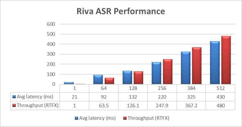 Figure 1. NVIDIA Riva ASR Performance
The objective of these tests is to have the lowest latency with the highest throughput. Throughput is measured in RTFX, or the duration of audio transcribed divided by computation time. During these tests, the GPU utilization was approximately 48% without any PowerFlex storage bottlenecks. These results are comparable to NVIDIA’s own findings in in the NVIDIA Riva User Guide.
The Dell PowerFlex Solutions Engineering team went beyond just looking at how fast NVIDIA Riva could transcribe text, also exploring the speed at which it could convert text to speech (TTS). They validated this as well. Starting with a single stream, for each run the stream is changed to 4, 6, 8, and 10, as shown in the following graph.
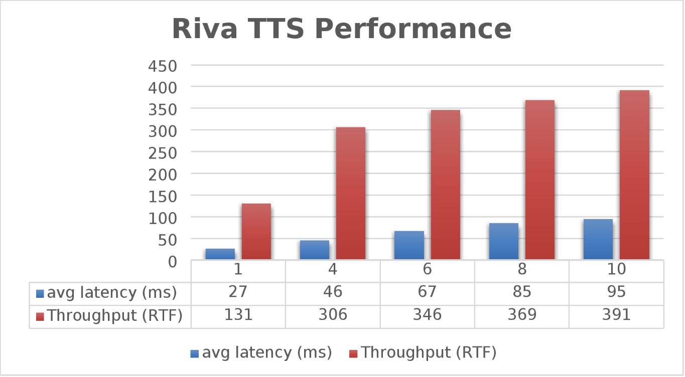 Figure 2. NVIDIA Riva TTS Performance
Again, the goal is to have a low average latency with a high throughput. The throughput (RTFX) in this case is the duration of audio generated divided by computation time. As we can see, this results in a RTFX throughput of 391 with a latency of 91ms with ten streams. It is also worth noting that during testing, GPU utilization was approximately 82% with no storage bottlenecks.
This is a lot of data to pack into one poster. Luckily, the Dell PowerFlex Solutions Engineering team created a validated architecture that details how all of these results were achieved and how an organization could replicate them if needed.
Now, to put all this into perspective, with PowerFlex you can achieve great results on both spoken language coming into your organization and converting text to speech. Pair this capability with some other generative AI (genAI) tools, like NVIDIA NeMo, and you can create some ingenious systems for your organization.
For example, if an ASR model is paired with a large language model (LLM) for a help desk, users could ask it questions verbally, and—once it found the answers—it could use TTS to provide them with support. Think of what that could mean for organizations.
It's amazing how a simple poster can hold so much information and so many possibilities. If you’re interested in learning more about the research Dell PowerFlex has done with NVIDIA Riva, visit the Poster Reception at NVIDIA GTC on Monday, March 18th from 4:00 to 6:00 PM. If you are unable to join us at the poster reception, the poster will be on display throughout NVIDIA GTC. If you are unable to attend GTC, check out the white paper, and reach out to your Dell representative for more information.
Authors: Tony Foster | Twitter: @wonder_nerd | LinkedIn
Praphul Krottapalli
Kailas Goliwadekar

Reaching the Summit, The Next Chapter of VxBlock History
Wed, 06 Mar 2024 15:34:48 -0000
|Read Time: 0 minutes
You stand atop a great mountain looking over all you have done to reach the summit. The air is thin and only a few have ever attempted to join you at these hallowed heights of success. This is the reality of VxBlock and indeed the converged infrastructure market.
As it has ascended to these heights over the last 13 years, the enterprise IT space has changed and morphed continually reinventing itself. We have seen the rise of hyperconverged infrastructure (HCI), cloud computing, containers, and software defined anything and everything. All these technologies have sprung to life during the decades long journey of VxBlock.
And like many of you, I have been there for this journey to the mountain top, this extraordinary adventure to do something new and unheard of in the marketplace. Today, the journey changes, today we start the next chapter of VxBlock history.
We are turning the page on VxBlock, we are creating a 3-Tier reference architecture to allow anyone to build a 3-Tier architecture. You can scale the mountain and embrace 3-Tier in your data center, but you don’t have to do it alone.
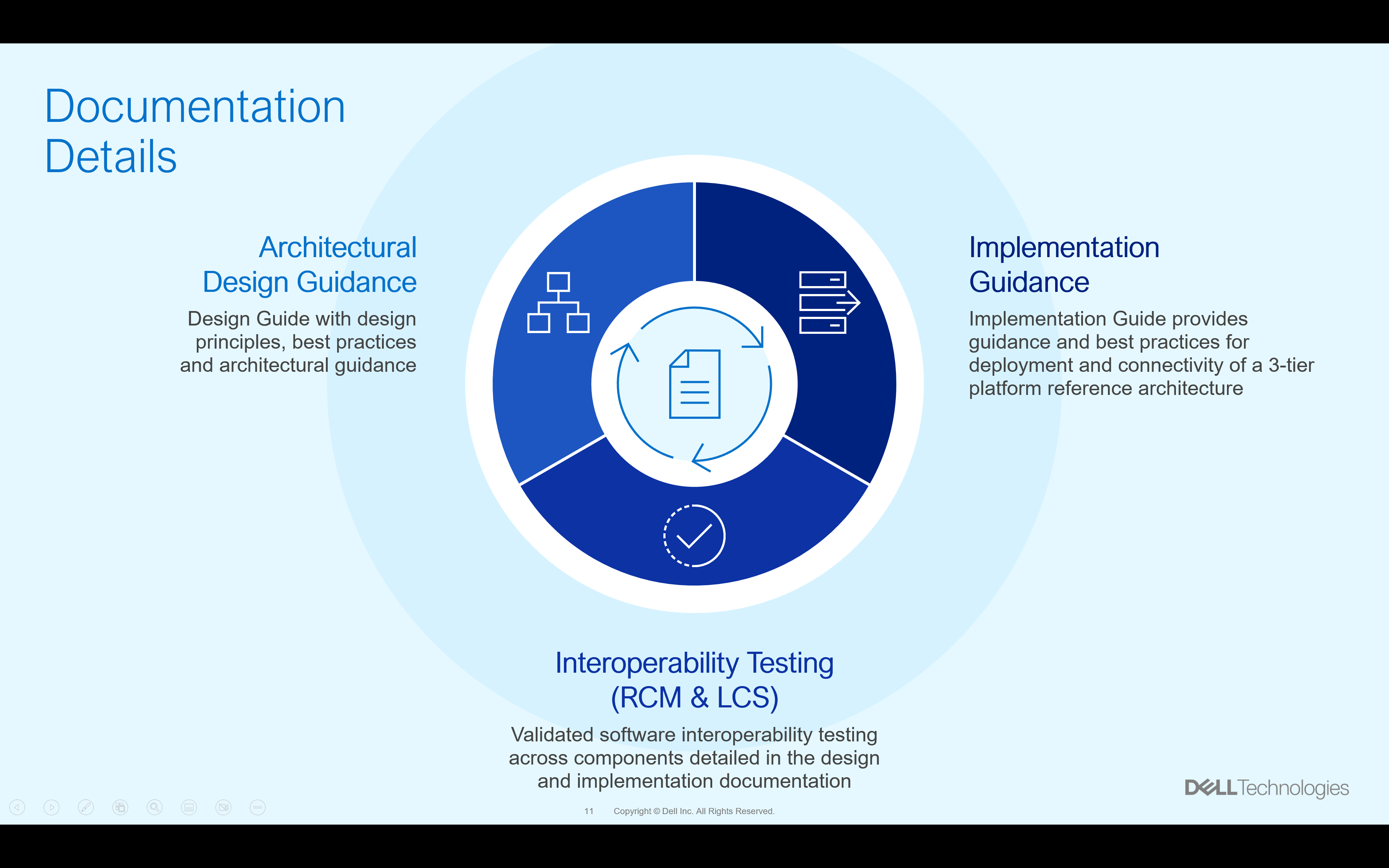
A traditional reference architecture is merely a map to follow. We all know to scale the high peaks of enterprise IT you need more than a map, more than a single document as your guide. We realize this and provide four essential documents to guide you on you 3-Tier journey. There is a design guide that helps you plan your journey. There is also an implementation guide to help assemble the right parts for your converged architecture journey. And there are the Release Certification Matrix (RCM) and Logical Configuration Survey (LCS) materials to help you avoid both common and uncommon pitfalls that you may come across. This is shown in the overview below.
These last two pieces of knowledge, the RCM and LCS, allow you to take advantage of some of the same revolutionary items that are used with VxBlock systems. VxBlock users tend to be familiar with both, but for those new to the 3-Tier space, let us explain them in a little more detail.
The LCS or logical configuration survey, is a document that has been refined over a decade to capture all the points of integration for a new 3-Tier deployment. There is no need to guess what information you might need to have a successful build, as those details are captured in the LCS before you even begin to deploy a 3-Tier architecture. This includes the obvious things such as domain credentials as well as the not so obvious things like rack power requirements. This survey makes it much easier to attain a successful deployment.
The RCM or release certification matrix has been a staple of 3-Tier architectures for a long time and has made its way into many other architectures. What the RCM provides is a list of interoperable systems. This may not sound like much, after all, most RAs tell you the components that were tested in the design. The RCM is different, in that it’s not just about a single set of components. For example, a single server model. The RCM is comprised of several different components that can be incorporated into a 3-Tier architecture. Plus, it is even more detailed than that. It looks at code level interoperability. Can the firmware of a switch, a server, and an OS function together? The RCM can help answer that question. If you will, would you rather climb a mountain in a one-size-fits-all climbing shoe, or a pair of tailor made shoes that fit to you?
This has been a core feature of VxBlock since its inception and can now be utilized as a for interoperability as part of the 3-Tier reference architecture. The RCM provides a reference point as organizations continue the normal life of their VxBlocks. Then as VxBlock systems reach the end of their operational life, the RCM also provides a pathway to migrate to a 3-Tier reference architecture. If you will, a path for any organization to reach the summit of their IT aspirations.
You are probably wondering, how these documents result in a complete 3-teir architecture in your data center. Let’s look at how all the parts come together with all the documents that make up the 3-Teir Reference Architecture. You can see how they logically come together in the following graphic.
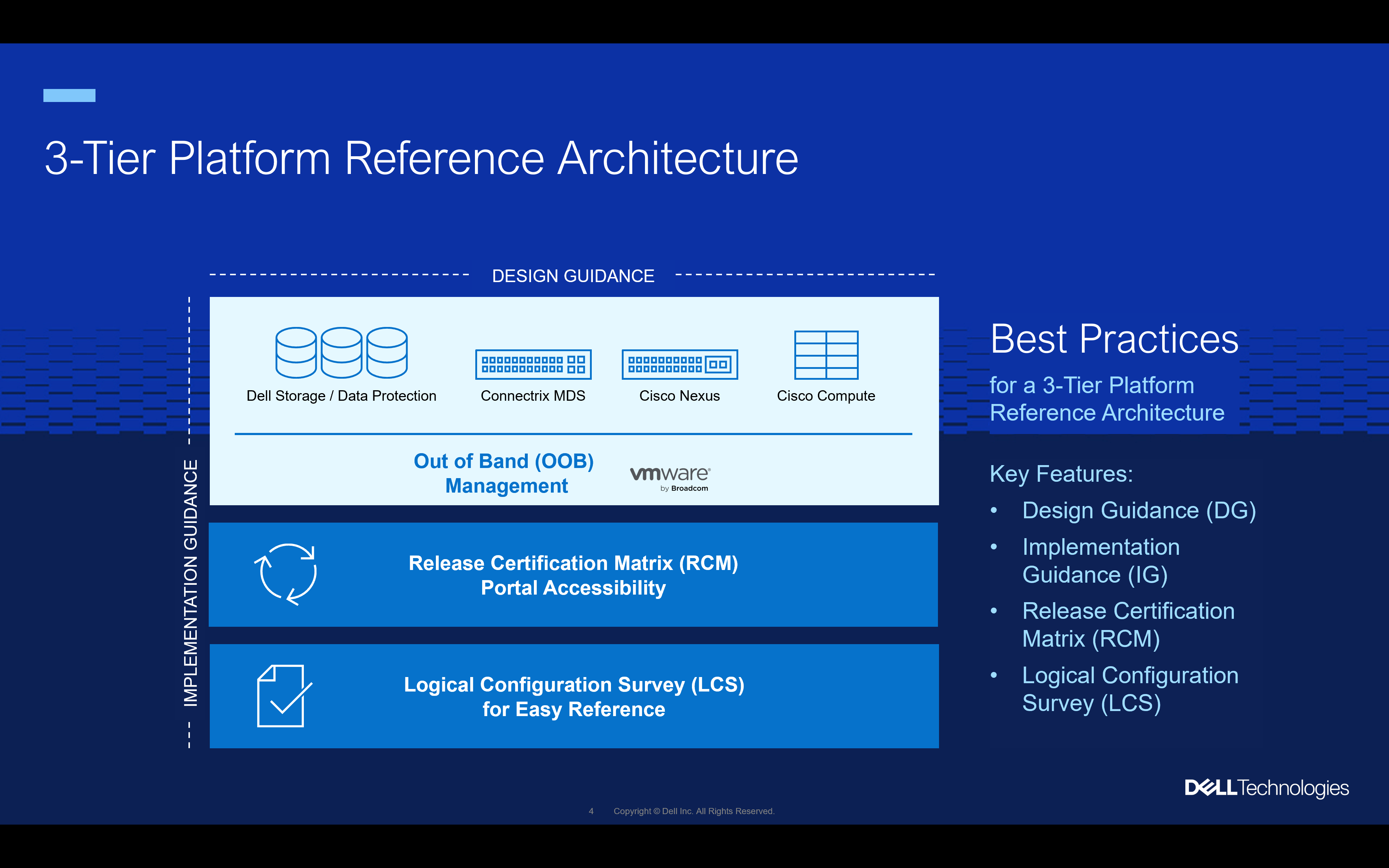
Start by preparing a plan for your environment. The 3-Tier Design Guide can help you with this along with a trusted advisor, such as Dell or another partner or VAR. Once you have a plan in place, you will need to order the infrastructure for your design. That includes the standard items you see in the diagram above like storage, switching, and compute. It also includes things you may not have thought of like racks and cables. No one climbs a mountain without first having a plan.
Something worth noting at this point is, you’ll need to purchase maintenance on each piece of equipment purchased. Similar to how one wouldn’t expect climbing gear and tents to be covered by the same warranty.
Now comes the exciting decision, who’s going to assemble your powerful 3-Tier reference architecture? There are three pathways to choose from. You can have all the gear land on your dock, and you can assemble it yourself by following the Implementation Guide. Of course, that is spending a lot of time just keeping the data center humming. There are other options that might yield a better return on investment for your organization.
You could have someone who is skilled at assembly assemble it for you, following the Implementation Guide, RCM, and LCS. There are many partners who can help you design and build a tailored 3-Tier architecture using the four documents discussed above. Additionally, Dell offers Enterprise Integration Services where a Dell team will work with you to integrate components into a 3-Tier architecture using a build methodology based on the documents above.
Whichever way you choose to assemble the design, the result is a 3-Tier platform for your datacenter. The process could look something like the diagram below. Where the individual components are purchased, then assembled according to the documentation, and finally consumed as a single operational system.
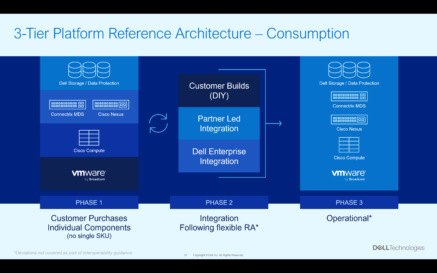
Having a structured architecture like this makes the journey to an operational state much easier. Much like climbing a mountain, a well-tested path is a quicker way to the summit.
Dell has made this journey an open process for anyone looking to deploy a 3-Tier architecture in their environment. The team has created more than a typical reference architecture, they have provided access to design guidance, implementation guidance, a release certification matrix (RCM), and a logical configuration survey (LCS).
Having all of these resources, is not only like having a map to the summit, but a trained guide with a full understanding of the mountain and a support system every step of the way until you reach the summit. If you’re interested in finding out more about using 3-Tier architectures in your environment, reach out to your Dell representative.

Dell PowerFlex – For Business-Critical Workloads and AI
Wed, 21 Feb 2024 00:10:52 -0000
|Read Time: 0 minutes
AI—the buzzword that dances on the tongues of tech enthusiasts, executives, and coffee-break conversationalists alike. It's the shiny promise of automation, insights, and futuristic marvels. But let's step back from the AI dazzle for a moment. Beneath the glitz lies a fundamental truth: business-critical applications are the unsung heroes of organizational success. Enter Dell PowerFlex, the sturdy workhorse that ensures these applications run seamlessly.
The AI hype revisited
Imagine a room abuzz with anticipation. Faces lean forward, eager for the next AI revelation. If you've followed my previous blog, Can I Do That AI Thing on Dell PowerFlex, you know the answer. Yes, you can do that AI thing on PowerFlex. Being able to do AI shouldn’t be the end all be all for organizations. In fact, for most, it’s probably only a small portion of their IT operations. To that end, Dell PowerFlex isn't just built for AI. In fact, PowerFlex’s real strength isn’t AI at all.
Crushing the AI illusion
Let's peel back the layers. Dell PowerFlex isn't a mystical crystal ball, predicting stock market trends or composing poetry. Instead, it's the backbone supporting everyday business operations. Think databases, application servers, file servers—the workhorses that keep your organization humming. These workloads are the lifeblood of any enterprise, and their smooth functioning is non-negotiable. For many organizations, AI operations are a distant second. Why not optimize for the workhorses as well as prepare to support that new AI model?
The workload warriors
- Databases: Customer data, financial records, and inventory details all reside in databases. Dell PowerFlex ensures their availability, scalability, and performance.
- Application Servers: The engines behind web applications, APIs, and services. PowerFlex flexes its muscles here, providing the horsepower needed for user requests, transactions, and data processing.
- File Servers: Shared drives, document repositories, and collaboration spaces rely on file servers. PowerFlex ensures your files flow smoothly, whether you're sharing a presentation or collaborating on a project.
- And So Many Others: ERP systems, CRM platforms, virtual desktops—the list goes on. Each workload has its quirks, demands, and deadlines. Dell PowerFlex steps up, offering a unified platform that simplifies management and boosts performance.
Business-critical, Dell PowerFlex vital
These business-critical workloads are the heartbeat of organizations. They power customer interactions, financial transactions, and strategic decision-making. When these workloads hiccup, the entire operation feels it. That's where Dell PowerFlex shines. Its architecture leverages a robust and resilient software-defined storage (SDS) platform. Translation? It's agile, scalable, and resilient.
So, what's the secret sauce? PowerFlex leverages distributed storage resources, creating a pool of compute and storage nodes. These nodes collaborate harmoniously, distributing data and handling failures gracefully. Whether you're running a database query, serving up a web page, or analyzing mountains of data, PowerFlex ensures the show goes on.
The PowerFlex promise
Dell PowerFlex isn't just a hardware box—it's a promise. A promise to keep your workloads humming, your data secure, and your business thriving. So, the next time AI dazzles you with its potential, remember that PowerFlex is the sturdy engine of reliability in the background, ensuring the lights stay on, the servers stay responsive, and the wheels of progress keep turning.
In the grand scheme of IT, Dell PowerFlex takes center stage—an unassuming force that holds everything together. And as we navigate the AI landscape, let's tip our hats to the real heroes who keep the gears turning, one workload—AI included—at a time.
In the interest of full disclosure, this blog was created with the assistance of AI.
Author: Tony Foster
Twitter: @wonder_nerd
LinkedIn

PowerFlex and CloudStack, an Amazing IaaS match!
Sat, 18 Nov 2023 14:13:00 -0000
|Read Time: 0 minutes
Have you heard about Apache CloudStack? Did you know it runs amazingly on Dell PowerFlex? And what does it all have to do with infrastructure as a service (IaaS)? Interested in learning more? If so, then you should probably keep reading!
The PowerFlex team and ShapeBlue have been collaborating to bring ease and simplicity to CloudStack on PowerFlex. They have been doing this for quite a while. As new versions are released, the teams work together to ensure it continues to be amazing for customers. The deep integration with PowerFlex makes it an ideal choice for organizations building CloudStack environments.
Both Dell and ShapeBlue are gearing up for the CloudStack Collaboration Conference (CCC) in Paris on November 23 and 24th. The CloudStack Collaboration Conference is the biggest get-together for the Apache CloudStack Community, bringing vendors, users, and developers to one place to discuss the future of open-source technologies, the benefits of CloudStack, new integrations, and capabilities.
CloudStack is open-source software designed to deploy and manage large networks of virtual machines as a highly available, highly scalable Infrastructure as a Service (IaaS) cloud computing platform. CloudStack is used by hundreds of service providers around the world to offer public cloud services and by many companies to provide an on-premises (private) cloud offering or as part of a hybrid cloud solution.
Users can manage their cloud with an easy to use Web interface, command line tools, and/or a full-featured RESTful API. In addition, CloudStack provides an API that is compatible with AWS EC2 and S3 for organizations that want to deploy hybrid clouds.
CloudStack can leverage the extensive PowerFlex REST APIs to enhance functionality. This facilitates streamlined provisioning, effective data management, robust snapshot management, comprehensive data protection, and seamless scalability, making the combination of PowerFlex storage and CloudStack a robust choice for modern IaaS environments.
You can see this in the following diagram. CloudStack and PowerFlex communicate with each other using APIs to coordinate operations for VMs. This makes it easier to administer larger environments, enabling organizations to have a true IaaS environment.
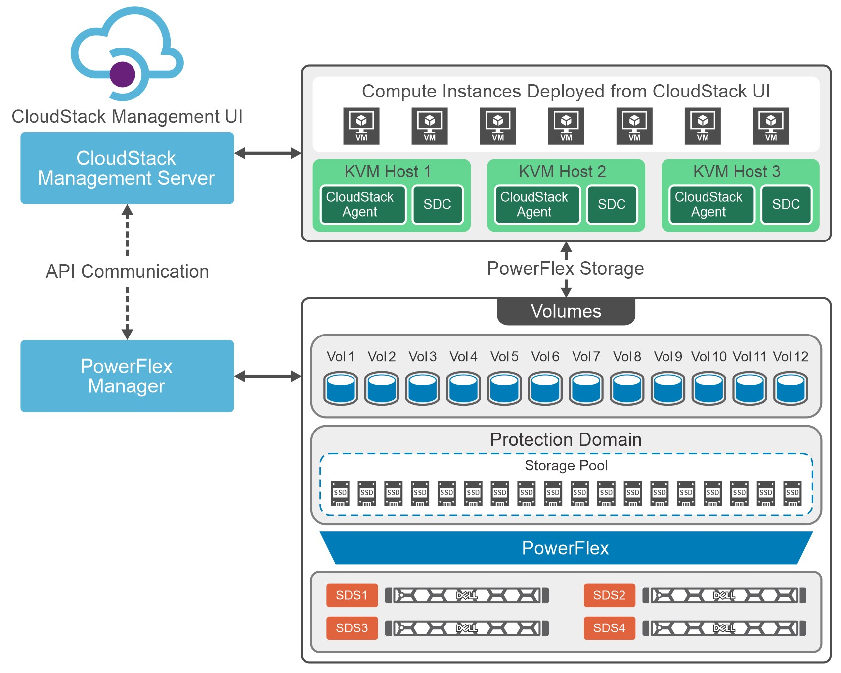
Figure 1. Cloud Stack on PowerFlex Architecture
Let's talk about IaaS for a moment. It is a fantastic concept that can be compared with ordering off a menu at a restaurant. The restaurant has unrelated dishes on the menu until you start looking at their components. For example, you can get three different base sauces (red, pink, and white) with just a red sauce and a white sauce. With a small variety of pasta and proteins, the options are excellent. This is the same for IaaS. Have a few base options, sprinkle on some API know-how, and you get a fantastic menu to satisfy workload needs without having a detailed knowledge of the infrastructure.
That makes it easier for the IT organization to become more efficient and shift the focus toward aspirational initiatives. This is especially true when CloudStack and PowerFlex work together. The hungry IT consumers can get what they want with less IT interaction.
Other significant benefits that come from integrating CloudStack with PowerFlex include the following:
- Seamless Data Management: Efficient provision, backup, and data management across infrastructure, ensuring data integrity and accessibility.
- Enhanced Performance: Provides low-latency access to data, optimizing I/O, and reducing bottlenecks. This, in turn, leads to improved application and workload performance.
- Reliability and Data Availability: Benefit from advanced redundancy and failover mechanisms and data replication, reducing the risk of data loss and ensuring continuous service availability.
- Scalability: Scalable storage solutions allow organizations to expand their storage resources in tandem with their growing needs. This flexibility ensures that they can adapt to changing workloads and resource requirements.
- Simplified Management: Ability to use a single interface to handle provisioning, monitoring, troubleshooting, and streamlining administrative tasks.
- Enhanced Data Protection: Data protection features, such as snapshots, backups, and disaster recovery solutions. This ensures that an organization's data remains secure and can be quickly restored in case of unexpected incidents.
These are tremendous benefits for organizations, especially the data protection aspects. It is often said that it is no longer a question of if an organization will be impacted by an incident. It is a question of when they will be impacted. The IaaS capabilities of CloudStack and PowerFlex play a crucial role in protecting an organization's data. That protection can be automated as part of the IaaS design. That way, when a VM or VMs are requested, they can be assigned to a data protection policy as part of the creation process.
Simply put, that means that VM can be protected from the moment of creation. No more having to remember to add a VM to a backup, and no more "oh no" when someone realizes they forgot. That is amazing!
If you are at the CloudStack Collaboration Conference and are interested in discovering more, talk with Shashi and Florian. They will also present how CloudStack and PowerFlex create an outstanding IaaS solution.
Register for the CloudStack Collaboration Conference here to join virtually if you are unable to attend in person.
If you want to learn more about how PowerFlex and CloudStack can benefit your organization, reach out to your Dell representative for more details on this amazing solution.
Resources
Authors
Tony Foster
Twitter: @wonder_nerd
LinkedIn
Punitha HS
LinkedIn

KubeCon NA23, Google Cloud Anthos on Dell PowerFlex and More
Sun, 05 Nov 2023 23:26:43 -0000
|Read Time: 0 minutes
KubeCon will be here before you know it. There are so many exciting things to see and do. While you are making your plans, be sure to add a few things that will make things easier for you at the conference and afterwards.
Before we get into those things, did you know that the Google Cloud team and the Dell PowerFlex team have been collaborating? Recently Dell and Google Cloud published a reference architecture: Google Cloud Anthos and GDC Virtual on Dell PowerFlex. This illustrates how both teams are working together to enable consistency between cloud and on premises environments like PowerFlex. You will see this collaboration at KubeCon this year.
On Tuesday at KubeCon, after breakfast and the keynote, you should make your way to the Solutions Showcase in Hall F on Level 3 of the West building. Once there, make your way over to the Google Cloud booth and visit with the team! They want your questions about PowerFlex and are eager to share with you how Google Distributed Cloud (GDC) Virtual with PowerFlex provides a powerful on-premises container solution.
Also, be sure to catch the lightning sessions in the Google Cloud booth. You’ll get to hear from Dell PowerFlex engineer, Praphul Krottapalli. He will be digging into leveraging GDC Virtual on PowerFlex. That’s not the big thing though, he’ll also be looking at running a Postgres database distributed across on-premises PowerFlex nodes using GDC Virtual. Beyond that, they will look at how to protect these containerized database workloads. They’ll show you how to use Dell PowerProtect Data Manager to create application consistent backups of a containerized Postgres database instance.
We all know backups are only good if you can restore them. So, Praphul will show you how to recover the Postgres database and have it running again in no time.
Application consistency is an important thing to keep in mind with backups. Would you rather have a database backup where someone had just pulled the plug on the database (crash consistent) or would you like the backup to be as though someone had gracefully shut down the system (application consistent)? For all kinds of reasons (time, cost, sanity), the latter is highly preferable!
We talk about this more in a blog that covers the demo environment we used for KubeCon.
This highlights Dell and Google’s joint commitment to modern apps by ensuring that they can be run everywhere and that organizations can easily develop and deploy modern workloads.
If you are at KubeCon and would like to learn more about how containers work on Dell solutions, be sure to stop by both the Dell and Google Cloud booths. If it’s after KubeCon, be sure to reach out to your Dell representative for more details.
Author: Tony Foster

Using Dell PowerFlex and Google Distributed Cloud Virtual for Postgres Databases and How to Protect Them

Fri, 03 Nov 2023 23:27:04 -0000
|Read Time: 0 minutes
Did you know you can get the Google Cloud experience in your data center? Well now, you can! Using Google Distributed Cloud (GDC) Virtual and Dell PowerFlex enables the use of cloud and container workloads – such as Postgres databases – in your data center.
Looking beyond day one operations, the whole lifecycle must be considered, which includes assessing how to protect these cloud native workloads. That’s where Dell PowerProtect Data Manager comes in, allowing you to protect your workloads both in the data center and the cloud. PowerProtect Data Manager enhances data protection by discovering, managing, and sending data directly to the Dell PowerProtect DD series virtual appliance, resulting in unmatched efficiency, deduplication, performance, and scalability. Together with PowerProtect Data Manager, the PowerProtect DD is the ultimate cyber resilient data protection appliance.
In the following blog, we will unpack all this and more, giving you the opportunity to see how Dell PowerFlex and GDC Virtual can transform how you cloud.
What is Google Distributed Cloud Virtual?
We will start by looking at GDC Virtual and how it allows you to consume the cloud on your terms.
GDC Virtual provides you with a consistent platform for building and managing containerized applications across hybrid infrastructures and helps your developers become more productive across all environments. GDC Virtual provides all the mechanisms required to bring your code into production reliably, securely, and consistently while minimizing risk. GDC Virtual is built on open-source technologies pioneered by Google Cloud including Kubernetes and Istio, enabling consistency between cloud and on premises environments like PowerFlex. Anthos GKE (on GCP and on-prem), Anthos Service Mesh, and Anthos Config Management are the core building blocks of Anthos, which has integrations with platform-level services such as Stackdriver, Cloud Build, and Binary Authorization. GDC Virtual users purchase services and resources from the GCP Marketplace.
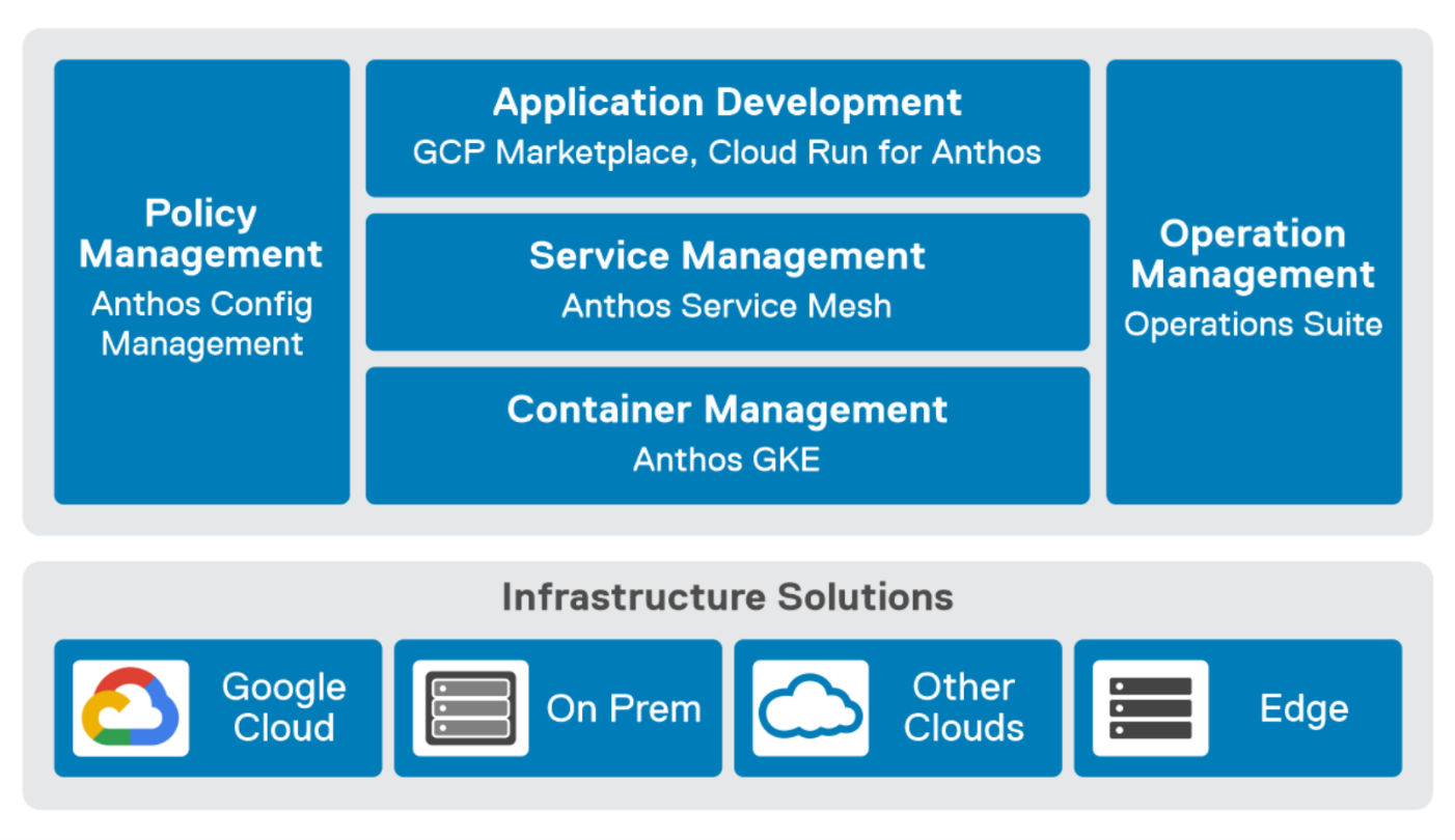
Figure 1. GDC Virtual components.
GDC Virtual puts all your IT resources into a consistent development, management, and control framework, automating low-value tasks across your PowerFlex and GCP infrastructure.
Within the context of GCP, the term ‘hybrid cloud’ describes a setup in which common or interconnected services are deployed across multiple computing environments, which include public cloud and on-premises. A hybrid cloud strategy allows you to extend the capacity and capabilities of your IT without the upfront capital expense investments of the public cloud while preserving your existing investments by adding one or more cloud deployments to your existing infrastructure. For more information, see Hybrid and Multi-Cloud Architecture Patterns.
PowerFlex delivers software defined storage to both virtual environments and bare metal hosts providing flexible consumption or resources. This enables both two-tier and three-tier architectures to match the needs of most any environment.
PowerFlex container storage
From the PowerFlex UI – shown in the following figure – you can easily monitor the performance and usage of your PowerFlex environment. Additionally, PowerFlex offers a container storage interface (CSI) and container storage modules (CSM) for integration with your container environment. The CSI/CSM allows containers to have persistent storage, which is important when working with workloads like databases that require it.
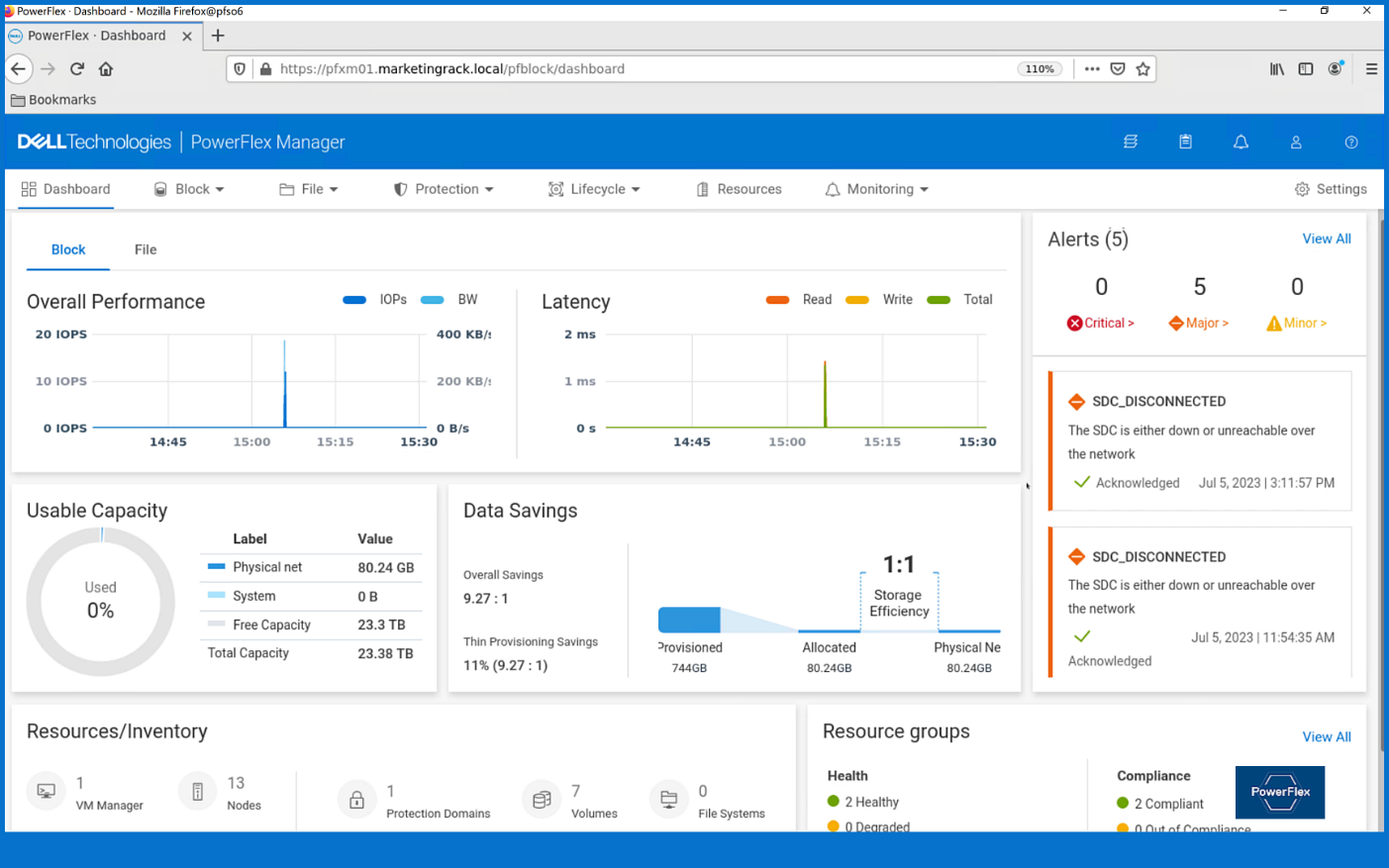
Figure 2. PowerFlex dashboard provides easy access to information.
To gain a deeper understanding of implementing GDC Virtual on Dell Powerflex, we invite you to explore our recently published reference architecture.
Dell engineers have recently prepared a PostgreSQL container environment deployed from the Google Cloud to a PowerFlex environment with GDC Virtual in anticipation of Kubecon. For those who have deployed Postgres from Google Cloud, you know it doesn’t take long to deploy. It took our team maybe 10 minutes, which makes it effortless to consume and integrate into workloads.
Once we had Postgres deployed, we proceeded to put it under load as we added records to it. To do this, we used pgbench, which is a built-in benchmarking tool in Postgres. This made it easy to fill a database with 10 million entries. We then used pgbench to simulate the load of 40 clients running 40 threads against the freshly loaded database.
Our goal wasn’t to capture performance numbers though. We just wanted to get a “warm” database created for some data protection work. That being said, what we saw on our modest cluster was impressive, with sub-millisecond latency and plenty of IO.
Data protection
With our containerized database warmed up, it was time to protect it. As you probably know, there are many ways to do this, some better than others. We’ll spend just a moment talking about two functional methods of data protection – crash consistent and application consistent backups. PowerProtect Data Manager supports both crash-consistent and application consistent database backups.
A “crash consistent” backup is exactly as the name implies. The backup application captures the volume in its running state and copies out the data regardless of what’s currently happening. It’s as if someone had just pulled the power cord on the workload. Needless to say, that’s not the most desirable backup state, but it’s still better than no backup at all.
That’s where an “application consistent” backup can be more desirable. An application consistent backup talks with the application and makes sure the data is all “flushed” and in a “clean” state prior to it being backed up. At least, that’s the simple version.
The longer version is that the backup application talks to the OS and application, asks them to flush their buffers – known as quiescing – and then triggers a snapshot of the volumes to be backed up. Once complete, the system then initiates a snapshot on the underlying storage – in this case PowerFlex – of the volumes used. Once the snapshots are completed, the application-level snapshots are released, the applications begin writing normally to it again, and the backup application begins to copy the storage snapshot to the protected location. All of this happens in a matter of seconds, many times even faster.
This is why application consistent backups are preferred. The backup can take about the same amount of time to run, but the data is in a known good state, which makes the chances of recovery much greater than crash consistent backups.
In our lab environment, we did this with PowerProtect Data Manager and PowerProtect DD Virtual Edition (DDVE). PowerProtect Data Manager provides a standardized way to quiesce a supported database, backup the data from that database, and then return the database to operation. This works great for protecting Kubernetes workloads running on PowerFlex. It’s able to create application consistent backups of the Postgres containers quickly and efficiently. This also works in concert with GDC Virtual, allowing for the containers to be registered and restored into the cloud environment.
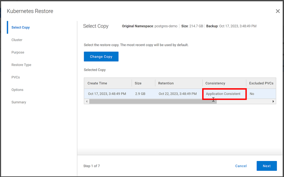
Figure 3. An application consistent backup and its timing in the PowerProtect Data Manager UI
It’s great having application consistent backups of your cloud workloads, “checking” many of those boxes that people require from their backup environments. That said, just as important and not to be forgotten is the recovery of the backups.
Data recovery
As has been said many times, “never trust a backup that hasn’t been tested.” It’s important to test any and all backups to make sure they can be recovered. Testing the recovery of a Postgres database running in GDC Virtual on PowerFlex is as straightforward as can be.
The high-level steps are:
- From the PowerProtect Data Manager UI, select Restore > Assets, and select the Kubernetes tab. Select the checkbox next to the protected namespace and click Restore.
- On the Select Copy page, select the copy you wish to restore from.
- On the Restore Type page, select where it should be restored to.
- Determine how the Persistent Volume Claims (PVCs) and namespace should be restored.
- When finished, test the restore.
You might have noticed in step 4, I mentioned PVCs, which are the container’s connections to the data and, as the name implies, allow that data to persist across the nodes. This is made possible by the CSI/CSM mentioned earlier. Because of the integration across the environment, restoring PVCs is a simple task.
The following shows some of the recovery options in PowerProtect Data Manager for PVCs.
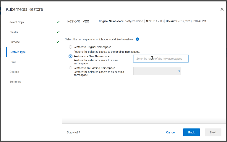
Figure 4. PowerProtect Data Manager UI – Namespace restore options
The recovery, like most things in data protection, is relatively anticlimactic. Everything is functional, and queries work as expected against the Postgres database instance.
Dell and Google Cloud collaborated extensively to create solutions that leverage both PowerFlex and GDC Virtual. The power of this collaboration really shows through when recovery operations just work. That consistency and ease enables customers to take advantage of a robust environment backed by leaders in the space and helps to remove one nightmare that keeps developers and IT admins awake at night, allowing them to rest easy and be prepared to change the world.
If any of this sounds interesting to you and you’ll be at Kubecon in Chicago, Illinois on November 6-9, stop by the Google Cloud booth. We’ll be happy to show you demos of this exciting collaboration in action. Otherwise, feel free contact your Dell representative for more details.
Resources
Authors:
Authors: | Tony Foster, | Vinod Kumar Kumaresan, | Harsha Yadappanavar, |
LinkedIn: | |||
X (formerly Twitter): |
| @harshauy | |
Personal Blog: |
|
|

Dell PowerFlex at VMware Explore in Barcelona – Nothing Controversial
Thu, 19 Oct 2023 22:38:22 -0000
|Read Time: 0 minutes
For those who aren’t aware, there are some big changes happening at VMware. If you watched the VMware Explore Las Vegas keynote, it was a whirlwind of changes and important information. CEOs of several major companies took the stage and spoke about the direction VMware is going, attendees hanging on their every word and wondering what the changes meant as well as how it would impact their operations.
For many, the impact is still unclear. This could radically change data centers and how organizations do work, leaving many in IT and business asking questions about what’s next and where things are headed.
We can all expect to find out more at VMware Explore Barcelona coming up 6 to 9 November, which will bring more clarity in direction and illuminate what it will mean for organizations large and small.
I can’t wait to see what’s in store for the Generative AI (GenAI) workloads we’ve all been waiting for (And you thought I was talking about something else?).
At VMware Explore in Las Vegas this year, the message was clear. VMware is embracing AI workloads. NVIDIA CEO Jensen Huang and VMware CEO Raghu Raghuram spoke to this during the general session keynote. Jensen stated, “we’re reinventing enterprise computing after a quarter of a century in order to transition to the future.”
The entire IT industry is moving in the direction of AI. Dell PowerFlex is already there. We’ve been on this journey for quite some time. If you were lucky enough to have stopped at the Kioxia stand during the Las Vegas show, you saw how we are working with both NVIDIA and Kioxia to deliver powerful AI systems for customers to make that transition to the future.
If you couldn’t make it to Las Vegas for VMware Explore but plan to attend VMware Explore in Barcelona, you’re in luck. PowerFlex will be showcasing the amazing performance of Kioxia storage and NVIDIA GPUs again. You can see a live demo at the Kioxia stand, #225 in the Solutions Exchange.
When you visit the Kioxia stand, you will be able to experience the power of running ResNet 50 image classification and Online Transactional Processing (OLTP) workloads simultaneously, live from the show floor. And if that’s not enough, there are experts and lots of them! If you get a chance, talk with Shashi about all the things PowerFlex unlocks for your organization.
PowerFlex supports NVIDIA GPUs with MIG technology, which is part of NVIDIA AI Enterprise. NVIDIA MIG allows you to tailor GPU resources for the workloads that need them (Yes, there is nothing that says you can’t run different workloads on the same hosts). Plus, PowerFlex uses Kioxia PM7 series SSDs, so there are plenty of IOPS to go around while ensuring sub-millisecond latency for both workloads. This allows the data to be closer to the processing, even on the same host.
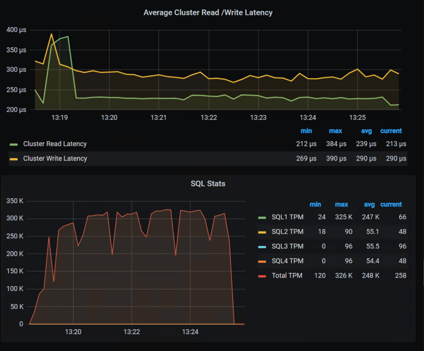
In our lab tests, we were able to push one million transactions per minute (TPM) with OLTP workloads while also processing 6620 images per second using a RESNET50 model built on NVIDIA NGC containers. These are important if you want to keep users happy, especially as more and more organizations want to add AI/ML capabilities to their online apps (and more and more data is generated from all those new apps).
The following shows the TPM results from the demo environment that is running our four SQL VMs. The TPMs in this test are maxing out around 320k, and the latency is always sub-millisecond.

The future is here and waiting for you to visit.
If you are unable to visit the stand and would like to get an overview of PowerFlex’s abilities when it comes to GenAI, check out this video.
As you can see, PowerFlex has true flexibility when it comes to GenAI, making it the ideal platform to reinvent your enterprise IT environment as you transition to the future.
If you find yourself at VMware Explore in Barcelona, be sure to stop by the Kioxia stand (#225) and talk with the team about how Dell PowerFlex, Kioxia drives, and NVIDIA GPUs can accelerate your transition to the future.
See, nothing controversial here!
Resources
- Dell Generative AI Solutions
- VMware and NVIDIA Unlock Generative AI for Enterprises
- VMware’s Approach to Private AI
Author: Tony Foster, Sr. Principal Technical Marketing Engineer
Twitter: | |
LinkedIn: | |
Personal Blog: | |
Location: | The Land of Oz [-6 GMT] |

Dell APEX Block Storage: It’s Not Where You Do Cloud, It’s How You Do Cloud
Fri, 13 Oct 2023 22:36:19 -0000
|Read Time: 0 minutes
The cloud isn’t just about where you are operating but how you are operating, a paradigm shift for many organizations. That’s where Dell APEX Block Storage comes in.
I’m not going to bore everyone with the history of Dell’s multicloud offerings announced at Dell Tech World and all the different APEX offerings being released. You can read all about those on the Dell APEX InfoHub. Instead, we’ll spend this bit of space talking about how Dell APEX cloud offerings systematically change how you do cloud rather than where you do cloud.
It’s safe to say that most readers here are familiar with the saying “the cloud is just someone else’s computer[s].” I even have a sticker someone gave me at a trade show a few years back with that quote, pictured here. The quote is commonly understood to say that the difference between operating in the cloud and in your own data center is where and whose computer you are using.
Figure 1. Sticker – There is no cloud, it’s just someone else’s computer
This is only a partially accurate statement though. By a show of hands, how many folks reading this would run their workloads the same way on someone else’s computer? You’re probably laughing and--if you work in IT security--potentially yelling at the screen right now. Why? Because it’s someone else’s computer! No one in IT would willingly move their workloads straight from the data center to a random computer and keep things the way they are. Rather, those systems would need to be reworked and reimagined to effectively “do cloud.”
We must approach the cloud as a mindset, not a location, asking “how can this workload be run on any computer — my computer, your computer, some “public” computer — and get the same results regardless?”. After all, it’s just someone else’s computer.
Diving into Dell APEX Block Storage
The Dell APEX offerings aren’t just another cloud, enabling organizations to readily adapt and adopt a cloud mindset for all workloads. For the sake of brevity, we’ll focus on the block storage varieties, Dell APEX Block Storage for AWS and Dell APEX Block Storage for Azure.
Dell APEX Block Storage allows you to consume cloud storage in either Azure or AWS. Both are powerful cloud platforms for enterprise workloads and PaaS offerings that aggregate low-cost cloud storage (just someone else’s storage) from the cloud provider to form cloud environments with enterprise-equivalent storage.
You might be asking, “what is ‘enterprise-equivalent storage?’” The answer may surprise you. Remember earlier when I described the cloud mindset of being able to run workloads anywhere? Adopting that, our workloads should function the same in the enterprise as well as in the cloud, encompassing not only performance (IOs and capacity) but also data resiliency, availability, and consistency across workloads.
But wait, only containerized workloads should run in “the cloud,” and those are already resilient. If a node goes down, just spin up another one. Why are containerized workloads special? Shouldn’t any workload be able to run anywhere, be it a traditional x86 application or a modern containerized app?
That’s why Dell APEX Block Storage is such an integral part of your organization’s cloud journey, enabling you to run any workload in any location and have the same experience. Who doesn’t want choice?
Beyond a consistent approach for consuming storage, the performance of that storage should be uniform across environments as well. Meaning, if you need a given number of IOPS or amount of storage capacity for a workload, they are imperative regardless of if it runs in your data center or on someone else’s computer (AKA the cloud).
The cloud provides many ways to satisfy resource requirements, some easy and some not so easy. If you want that consistent method for managing your data and workloads both on premises and in the cloud, Dell APEX Block storage makes it easy. It can aggregate cloud storage into a consistent, scale-out, software defined block storage service. Dell APEX Block Storage enables you to consume block storage from the cloud the same way you consume it in your own data center.
Deploying APEX Block Storage
Let’s walk through this concept. First, log in to your organization's Dell Premier Account. From the right-hand menu, select the Discover and Deploy option, then click on Available Services. From there, you will see the option, if entitled, to create a new APEX Block Storage instance. That can either be deployed on Amazon AWS or Microsoft Azure, as depicted in figure 2.
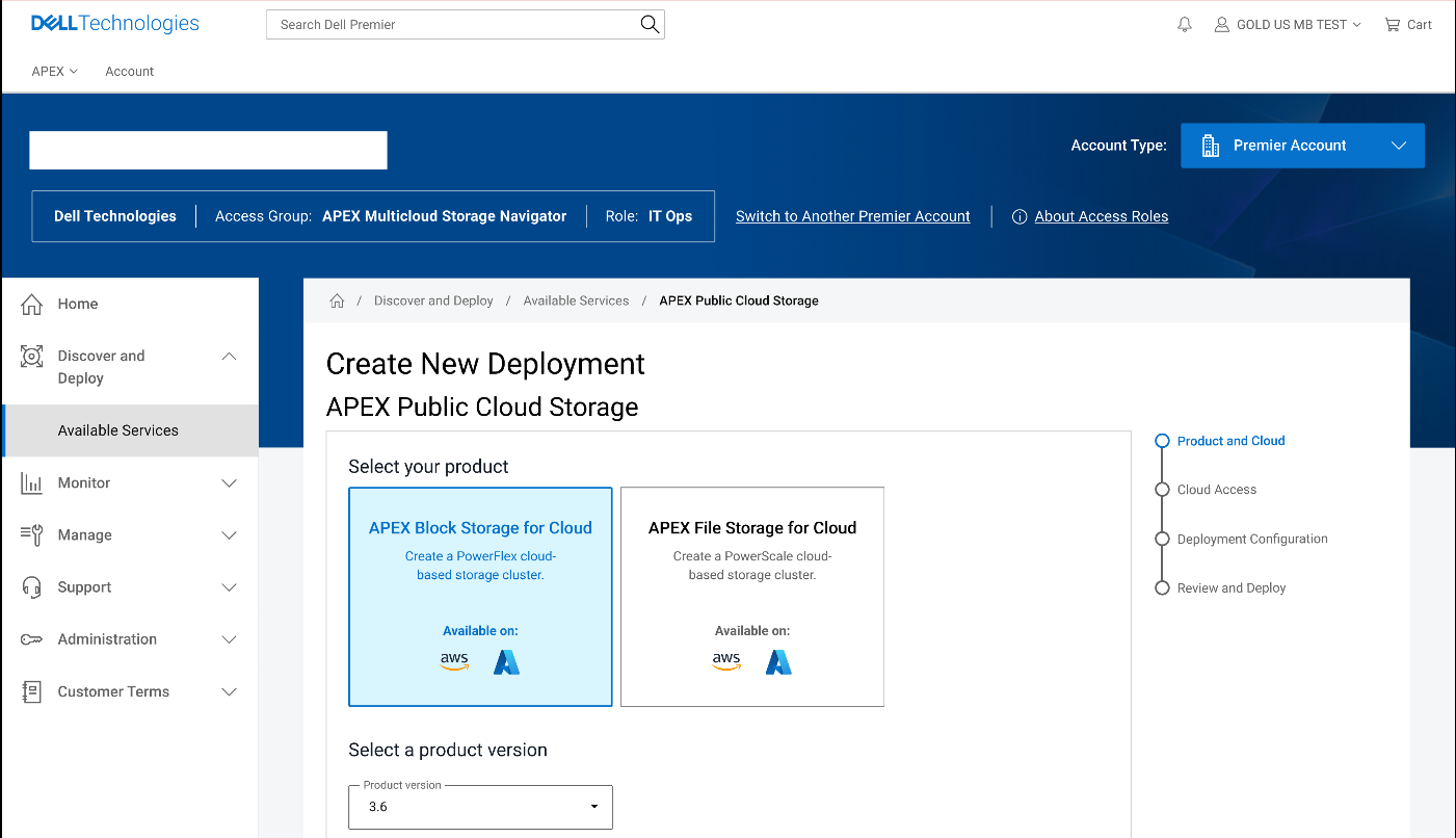
Figure 2. Dell Premier Account with APEX Block Storage capabilities enabled
Once you have completed the wizard, you will see additional instances or VMs in your cloud console of choice. The storage resources of these VMs (or instances) are aggregated to deliver APEX Block Storage that can be easily consumed. This is illustrated in the following figures for both APEX Block Storage for Azure and APEX Block Storage for AWS.
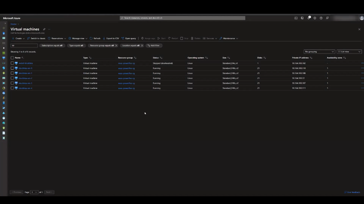
Figure 3. APEX Block Storage for Azure VMs
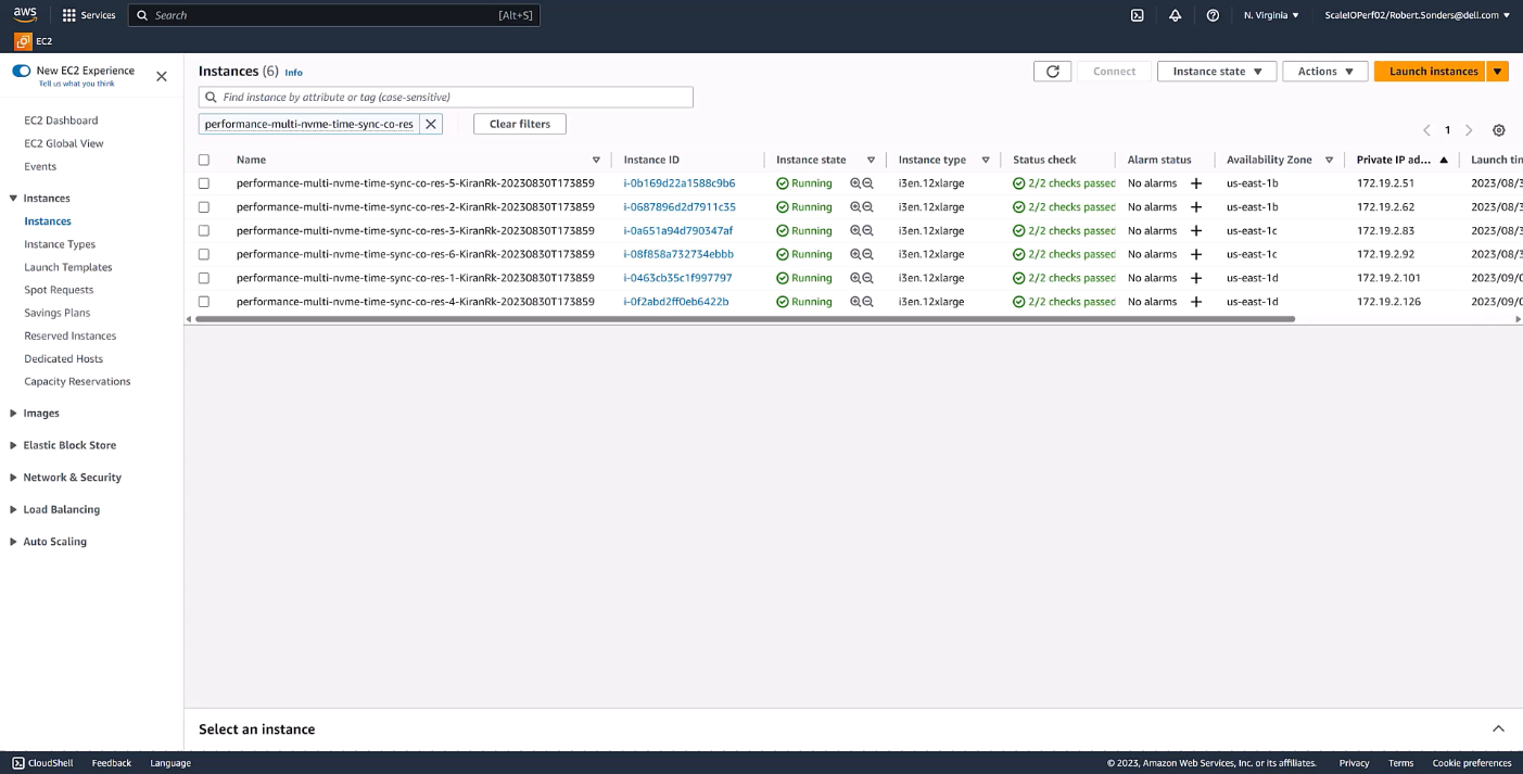
Figure 4. APEX Block Storage for AWS instances
What can APEX Block Storage do for you
The following diagram illustrates this aggregation and shows the relative ease with which storage can be expanded by simply adding an additional VM or instance in the cloud. You might be thinking, “that’s not a big deal, I’ve been doing that in my data center for several years”, and you’d be right. It shouldn’t be a big deal. Expanding storage should be the same, regardless of location.
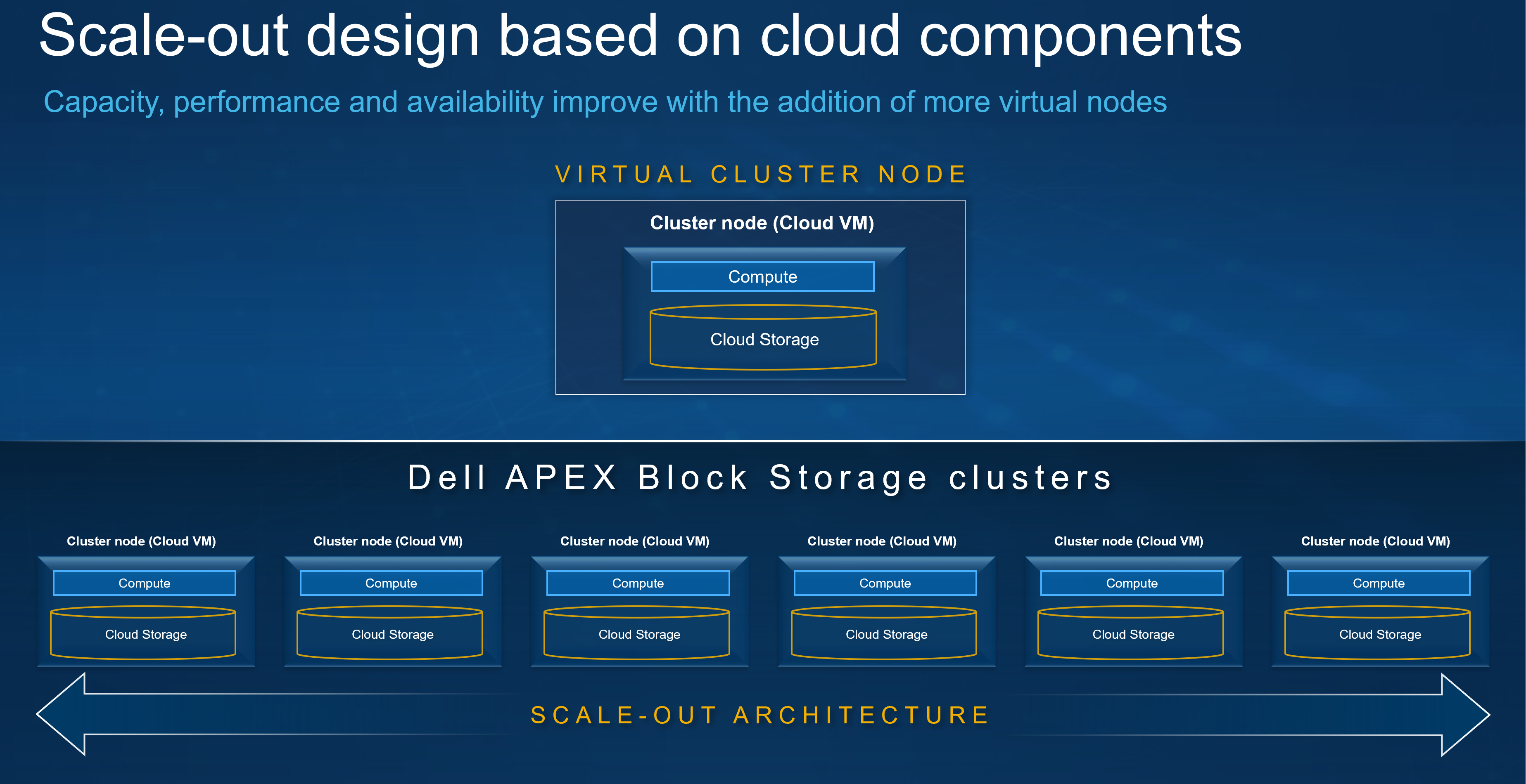
Figure 5. Aggregating storage with Dell APEX Block Storage
Something else that has been happening in the data center forever is thin provisioning. I remember back when I first started in IT how cool it was to have a SAN in the office that could thin provision. That meant I had a SAN with 16 – 500GB drives or about 7TB of usable space, allowing me to allocate terabytes of space to my systems even though I didn’t have the capacity to deliver it. If I ever needed too, I could scale out my capacity to meet the greater demand by adding another shelf to the array. It was awesome and powerful and — for a young IT admin — it sure made life easier. Since then, I’ve always considered thin provisioning when building storage systems, and it’s nice that I can be consistent in my planning wherever my workloads run.
Additionally, Dell APEX Block Storage enables space efficient snapshots in the cloud, helping reduce your space consumption. The reason space efficient snapshots are a big deal is because, instead of making a copy of everything, only the changed bits are recorded. That’s monumental when you’re paying for every IO and byte of space.
Not only do you get space efficient snapshots, you can also have a lot of them. We’re talking 126 snapshots per volume or roughly 32k snapshots per storage pool, unlocking an abundance of capabilities, especially in the cloud. Remember the whole cloud is a mindset thing? Having data center options at your disposal can come in handy regardless of where the operations are taking place.
Snapshots are nice, but they don’t mean a thing if you can’t do something with them — preferably at the same time you are using the rest of the volume. With APEX Block Storage, you can do just that. You can mount the snapshots and read from or write to them like they are another volume in the environment, similar to what you have been doing with storage in the data center for years.
Earlier, I mentioned scaling. In that regard, Dell APEX Block Storage has you covered. Starting with 10TiB of useable capacity and scaling up to 4PiB in the cluster, I can create volumes that are 8GB all the way up to 1PiB, producing massive flexibility for building in the cloud and empowering you to meet the storage needs of your most demanding applications.
As you increase the capacity, rest assured the performance with Dell APEX Block Storage remains linear. As you can see from the following charts for IOPS and throughput, both scale linearly on both reads and writes, meaning you get reliable and consistent performance from the cloud1. This provides the opportunity to apply a cloud mindset at scale, allowing you to focus on optimizing cloud workloads as the cloud infrastructure is ready for them.
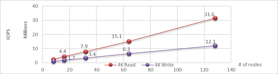
Figure 6. Linear IOPS as the number of nodes is increased in the APEX Block Storage environment
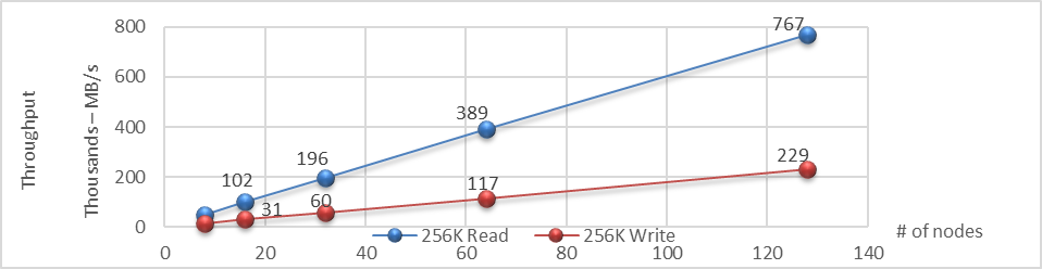
Figure 7. Linear throughput as the number of nodes is increased in the APEX Block Storage environment
Conclusion
Dell APEX Block Storage provides a host of capabilities, including aggregating underlying cloud storage into scalable and unified storage that linearly scales IOPS and throughput as new nodes are provided. We also looked at the availability of Dell APEX Block Storage in both Microsoft Azure and Amazon AWS clouds. Finally, we covered how cloud computing is a frame of mind to incorporate into our designs so our workloads can run in any location we choose.
Of course, the areas we went over just scratch the surface of applying a cloud mindset. After all, as we’ve said before, the cloud is just somebody else’s computer.
If you would like to find out more about how Dell APEX Block Storage can enhance your cloud journey, reach out to your Dell representative.
Resources
Author: Tony Foster, Sr. Principal Technical Marketing Engineer
Twitter: | |
LinkedIn: | |
Personal Blog: | |
Location: | The Land of Oz [-6 GMT] |
1Based on internal testing, March 15th-16th 2021 – Extreme SLAs – Even in the Cloud

VMware Explore, PowerFlex, and Silos of Glitter: this blog has it all!
Fri, 18 Aug 2023 19:30:20 -0000
|Read Time: 0 minutes
Those who know me are aware that I’ve been a big proponent of one platform that must be able to support multiple workloads—and Dell PowerFlex can. If you are at VMware Explore you can see a live demo of both traditional database workloads and AI workloads running on the same four PowerFlex nodes.
When virtualization took the enterprise by storm, a war was started against silos. First was servers, and the idea that we can consolidate them on a few large hosts with virtualization. This then rapidly moved to storage and continued to blast through every part of the data center. Yet today we still have silos. Mainly in the form of workloads, these hide in plain sight - disguised with other names like “departmental,” “project,” or “application group.”
Some of these workload silos are becoming even more stealthy and operate under the guise of needing “different” hardware or performance, so IT administrators allow them to operate in a separate silo.
That is wasteful! It wastes company resources, it wastes the opportunity to do more, and it wastes your time managing multiple environments. It has become even more of an issue with the rise of Machine Learning (ML) and AI workloads.
If you are at VMware Explore this year you can see how to break down these silos with Dell PowerFlex at the Kioxia booth (Booth 309). Experience the power of running ResNet 50 image classification and OLTP (Online Transactional Processing) workloads simultaneously, live from the show floor. And if that’s not enough, there are experts, and lots of them! You might even get the chance to visit with the WonderNerd.
This might not seem like a big deal, right? You just need a few specialty systems, some storage, and a bit of IT glitter… some of the systems run the databases, some run the ML workloads. Sprinkle some of that IT glitter and poof you’ve got your workloads running together. Well sort of. They’re in the same rack at least.
Remember: silos are bad. Instead, let’s put some PowerFlex in there! And put that glitter back in your pocket, this is a data center, not a five-year old’s birthday party.
PowerFlex supports NVIDIA GPUs with MIG technology which is part of NVIDIA AI Enterprise, so we can customize our GPU resources for the workloads that need them. (Yes, there is nothing that says you can’t run different workloads on the same hosts.) Plus, PowerFlex uses Kioxia PM7 series SSDs, so there is plenty of IOPS to go around while ensuring sub-millisecond latency for both workloads. This allows the data to be closer to the processing, maybe even on the same host.
In our lab tests, we could push one million transactions per minute (TPM) with OLTP workloads while also processing 6620 images per second using a RESNET50 model built on NVIDIA NGC containers. These are important if you want to keep customers happy, especially as more and more organizations add AI/ML capabilities to their online apps, and more and more data is generated from all those new apps.
Here are the TPM results from the demo environment that is running our four SQL VMs. The TPMs in this test are maxing out around 320k and the latency is always sub-millisecond. This is the stuff you want to show off, not that pocket full of glitter.
Yeah, you can silo your environments and hide them with terms like “project” and “application group,” but everyone will still know they are silos.
We all started battling silos at the dawn of virtualization. PowerFlex with Kioxia drives and NVIDIA GPUs gives administrators a fighting chance to win the silo war.
You can visit the NVIDIA team at Lounge L3 on the show floor during VMware Explore. And of course, you have to stop by the Kioxia booth (309) to see what PowerFlex can do for your IT battles. We’ll see you there!
Author: Tony Foster
Twitter: | |
LinkedIn: | |
Personal Blog: | |
Location: | The Land of Oz [-6 GMT] |
Contributors: Kailas Goliwadekar, Anup Bharti

Managing Dell PowerFlex Licensing and Being Way Less Sad
Mon, 24 Jul 2023 21:20:14 -0000
|Read Time: 0 minutes
Imagine there was an easy way to view and manage your Dell PowerFlex licenses. Wouldn’t that be nice? I know I’d be way less sad. Well guess what, I’m way less sad, and there’s a way to easily manage your PowerFlex licenses.
I was on a call today with one of our product managers. He was showing something really cool, and I just had to share it with everyone. You can go into CloudIQ and view all your PowerFlex licenses.
You might think, “big deal, licenses.” You’re right! It is a big deal. Okay, a moderate sized deal, it makes me less sad. And here’s why. Have you ever had to track licenses for your environment in a spreadsheet? How about sharing that spreadsheet with everyone else on your team and hoping that no one accidently removes too many rows or types in the wrong cell. Or maybe you have to correlate a license to how much capacity you’re using. I’m sure 90% of users love this method. What’s that I hear you yelling at your monitor, I’m wrong???
You’re correct, hardly anyone wants to track licenses that way. Why? Because its error prone and difficult to manage, plus it’s not automated. Oh, and it’s licensing. Well, CloudIQ can help you address a lot of this, at least for your PowerFlex environment.
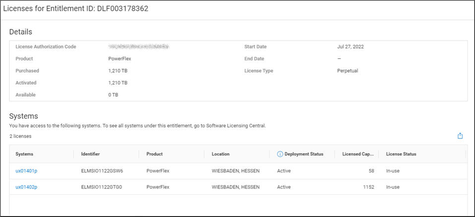
That’s right. You log in, click on the Entitlements and System Licenses option in the menu, and you can see all your entitlements for PowerFlex. With that you can see how many terabytes of capacity each license has as well as the start and end dates. It’s all there, no spreadsheets, no manual entry, it’s easy to manage. Maybe 90% of users would prefer this method over a spreadsheet. You can see this functionality in the screenshot below.
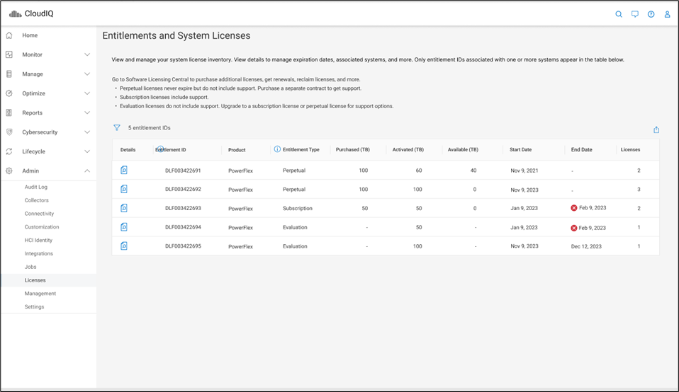
It gets better though…. Maybe you want to dig into the details of your environment and see how different licenses are being used. Maybe you are licensed for a petabyte of storage but you’re missing 50ish terabytes and want to see where they went. If you click on the details of an entitlement, you can see which systems are consuming capacity from the license. This makes it a lot easier than a spreadsheet to track down. You can see this in the following screenshot.
I’m sure it’s hard to get excited over licensing, but hopefully this makes you way less sad knowing you don’t have to try and track all this in a spreadsheet. Instead, you just log in to CloudIQ, then click on Entitlements and System Licenses. Poof, there it all is, in an easy-to-consume format. And for those who still want to manage their licenses in a spreadsheet, there’s an export option at the top of the table just for you. You can create pivot tables to your heart’s content. For everyone else, you’ve just unlocked a PowerFlex secret. Hopefully, like me, this makes you way less sad about licensing.
If you’re interested in finding out more about what you can do with licensing in CloudIQ, reach out to your Dell representative, who can guide you on all CloudIQ has to offer.
Author: Tony Foster
Sr. Principal Technical Marketing Engineer
Twitter: | |
LinkedIn: | |
Personal Blog: | |
Location: | The Land of Oz [-6 GMT] |

Can I do that AI thing on Dell PowerFlex?
Thu, 20 Jul 2023 21:08:09 -0000
|Read Time: 0 minutes
The simple answer is Yes, you can do that AI thing with Dell PowerFlex. For those who might have been busy with other things, AI stands for Artificial Intelligence and is based on trained models that allow a computer to “think” in ways machines haven’t been able to do in the past. These trained models (neural networks) are essentially a long set of IF statements (layers) stacked on one another, and each IF has a ‘weight’. Once something has worked through a neural network, the weights provide a probability about the object. So, the AI system can be 95% sure that it’s looking at a bowl of soup or a major sporting event. That, at least, is my overly simplified description of how AI works. The term carries a lot of baggage as it’s been around for more than 70 years, and the definition has changed from time to time. (See The History of Artificial Intelligence.)
Most recently, AI has been made famous by large language models (LLMs) for conversational AI applications like ChatGPT. Though these applications have stoked fears that AI will take over the world and destroy humanity, that has yet to be seen. Computers still can do only what we humans tell them to do, even LLMs, and that means if something goes wrong, we their creators are ultimately to blame. (See ‘Godfather of AI’ leaves Google, warns of tech’s dangers.)
The reality is that most organizations aren’t building world destroying LLMs, they are building systems to ensure that every pizza made in their factory has exactly 12 slices of pepperoni evenly distributed on top of the pizza. Or maybe they are looking at loss prevention, or better traffic light timing, or they just want a better technical support phone menu. All of these are uses for AI and each one is constructed differently (they use different types of neural networks).
We won’t delve into these use cases in this blog because we need to start with the underlying infrastructure that makes all those ideas “AI possibilities.” We are going to start with the infrastructure and what many now consider a basic (by today’s standards) image classifier known as ResNet-50 v1.5. (See ResNet-50: The Basics and a Quick Tutorial.)
That’s also what the PowerFlex Solution Engineering team did in the validated design they recently published. This design details the use of ResNet-50 v1.5 in a VMware vSphere environment using NVIDIA AI Enterprise as part of PowerFlex environment. They started out with the basics of how a virtualized NVIDIA GPU works well in a PowerFlex environment. That’s what we’ll explore in this blog – getting started with AI workloads, and not how you build the next AI supercomputer (though you could do that with PowerFlex as well).
In this validated design, they use the NVIDIA A100 (PCIe) GPU and virtualized it in VMware vSphere as a virtual GPU or vGPU. With the infrastructure in place, they built Linux VMs that will contain the ResNet-50 v1.5 workload and vGPUs. Beyond just working with traditional vGPUs that many may be familiar with, they also worked with NVIDIA’s Multi-Instance GPU (MIG) technology.
NVIDIA’s MIG technology allows administrators to partition a GPU into a maximum of seven GPU instances. Being able to do this provides greater control of GPU resources, ensuring that large and small workloads get the appropriate amount of GPU resources they need without wasting any.
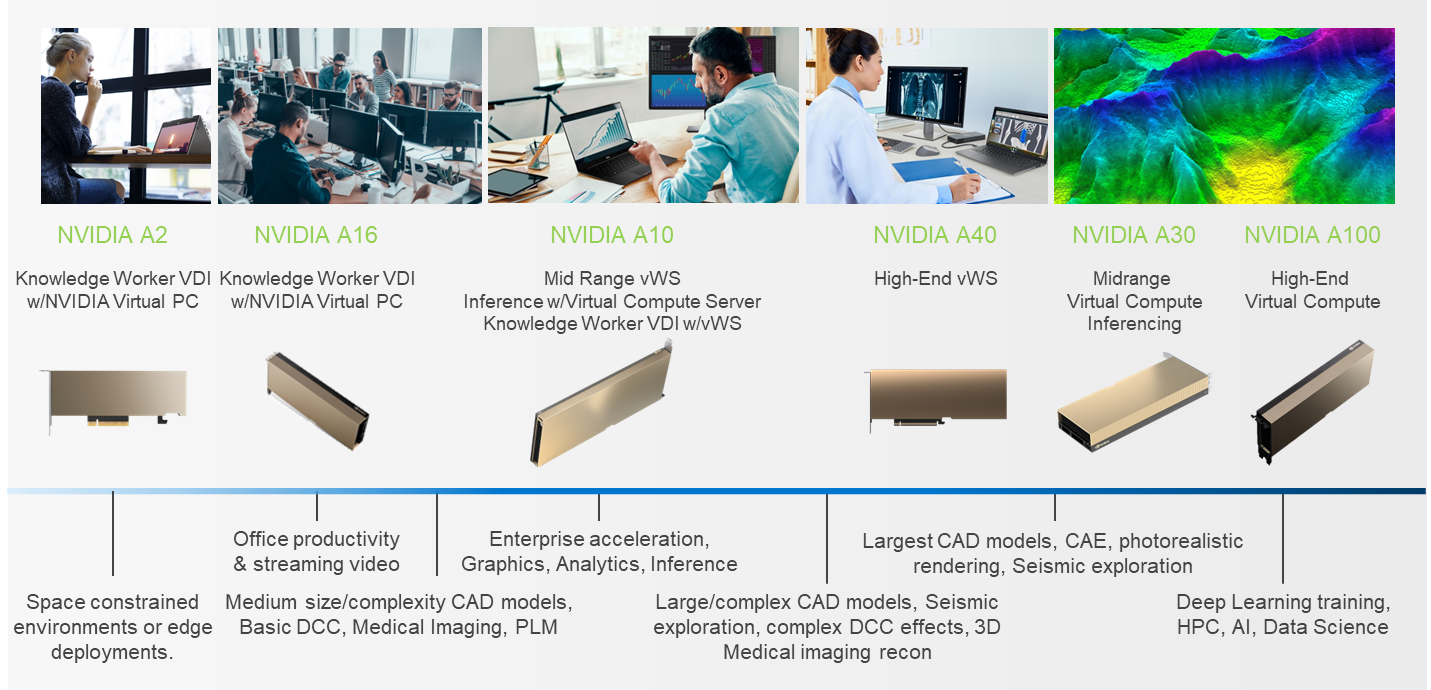
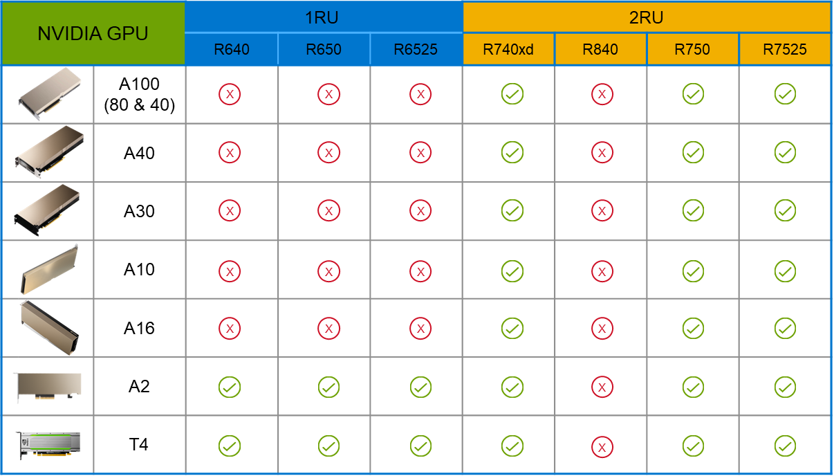
PowerFlex supports a large range of NVIDIA GPUs for workloads, from VDI (Virtual Desktops) to high end virtual compute workloads like AI. You can see this in the following diagram where there are solutions for “space constrained” and “edge” environments, all the way to GPUs used for large inferencing models. In the table below the diagram, you can see which GPUs are supported in each type of PowerFlex node. This provides a tremendous amount of flexibility depending on your workloads.
The validated design describes the steps to configure the architecture and provides detailed links to the NVIDIAand VMware documentation for configuring the vGPUs, and the licensing process for NVIDIA AI Enterprise.
These are key steps when building an AI environment. I know from my experience working with various organizations, and from teaching, that many are not used to working with vGPUs in Linux. This is slowly changing in the industry. If you haven’t spent a lot of time working with vGPUs in Linux, be sure to pay attention to the details provided in the guide. It is important and can make a big difference in your performance.
The following diagram shows the validated design’s logical architecture. At the top of the diagram, you can see four Ubuntu 22.04 Linux VMs with the NVIDIA vGPU driver loaded in them. They are running on PowerFlex hosts with VMware ESXi deployed. Each VM contains one NVIDIA A100 GPU configured for MIG operations. This configuration leverages a two-tier architecture where storage is provided by separate PowerFlex software defined storage (SDS) nodes.
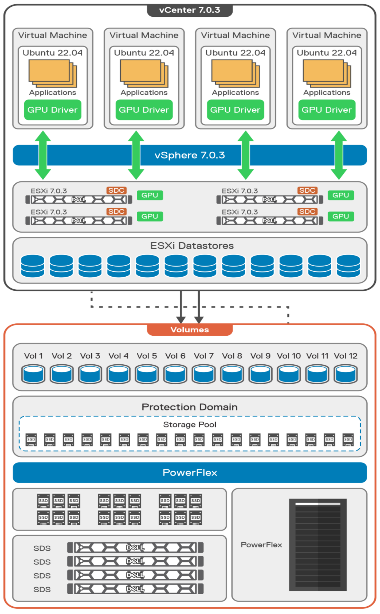
A design like this allows for independent scalability for your workloads. What I mean by this is during the training phase of a model, significant storage may be required for the training data, but once the model clears validation and goes into production, storage requirements may be drastically different. With PowerFlex you have the flexibility to deliver the storage capacity and performance you need at each stage.
This brings us to testing the environment. Again, for this paper, the engineering team validated it using ResNet-50 v1.5 using the ImageNet 1K data set. For this validation they enabled several ResNet-50 v1.5 TensorFlow features. These include Multi-GPU training with Horovod, NVIDIA DALI, and Automatic Mixed Precision (AMP). These help to enable various capabilities in the ResNet-50 v1.5 model that are present in the environment. The paper then describes how to set up and configure ResNet-50 v1.5, the features mentioned above, and details about downloading the ImageNet data.
At this stage they were able to train the ResNet-50 v1.5 deployment. The first iteration of training used the NVIDIA A100-7-40C vGPU profile. They then repeated testing with the A100-4-20C vGPU profile and the A100-3-20C vGPU profile. You might be wondering about the A100-2-10C vGPU profile and the A100-1-5C profile. Although those vGPU profiles are available, they are more suited for inferencing, so they were not tested.
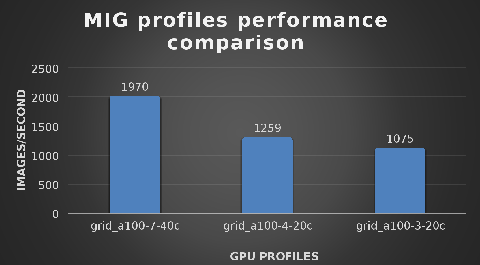
The results from validating the training workloads for each vGPU profile is shown in the following graph. The vGPUs were running near 98% capacity according to nvitop during each test. The CPU utilization was 14% and there was no bottle neck with the storage during the tests.
With the models trained, the guide then looks at how well inference runs on the MIG profiles. The following graph shows inferencing images per second of the various MIG profiles with ResNet-50 v1.5.
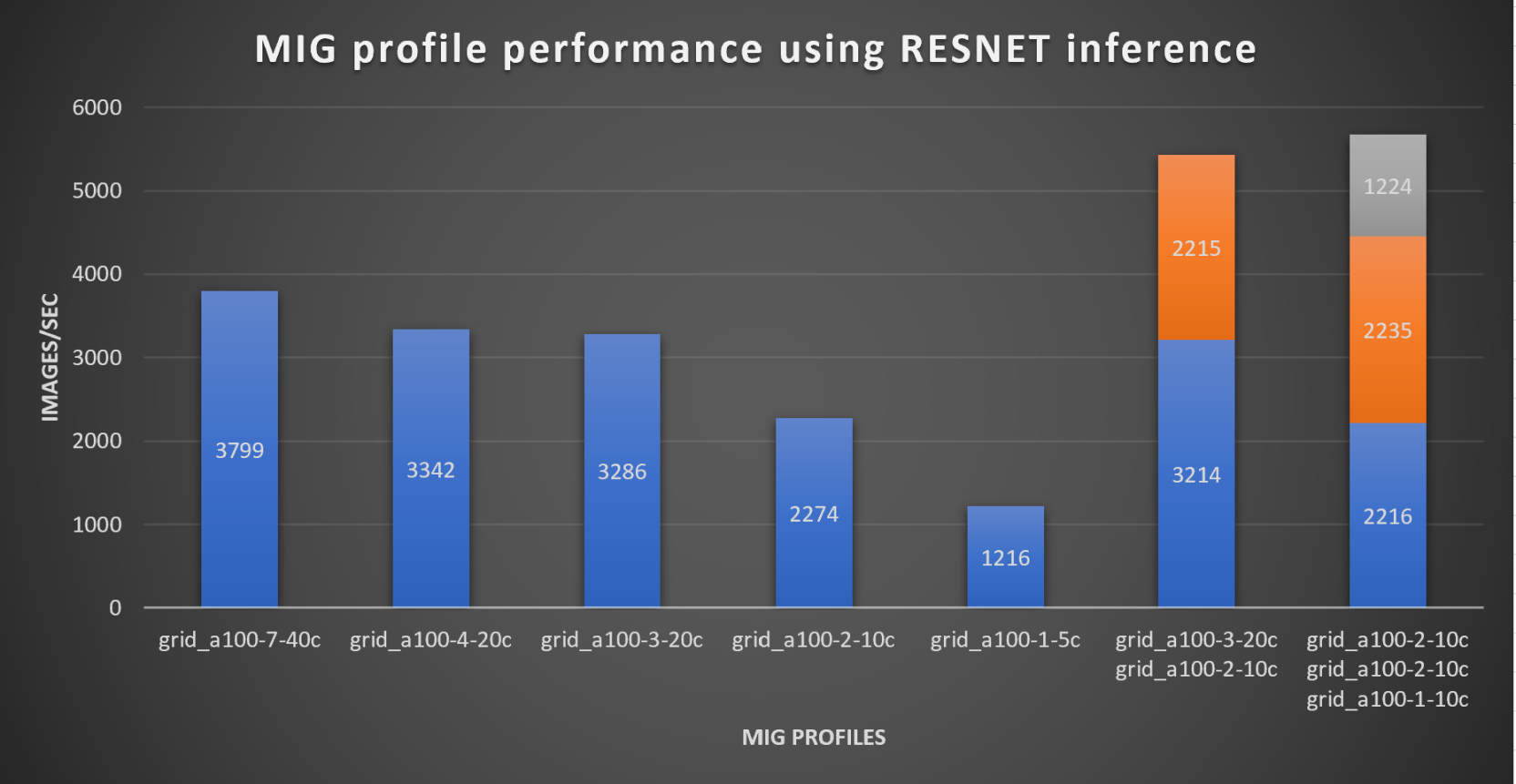
It’s worth noting that the last two columns show the inferencing running across multiple VMs, on the same ESXi host, that are leveraging MIG profiles. This also shows that GPU resources are partitioned with MIG and that resources can be precisely controlled, allowing multiple types of jobs to run on the same GPU without impacting other running jobs.
This opens the opportunity for organizations to align consumption of vGPU resources in virtual environments. Said a different way, it allows IT to provide “show back” of infrastructure usage in the organization. So if a department only needs an inferencing vGPU profile, that’s what they get, no more, no less.
It’s also worth noting that the results from the vGPU utilization were at 88% and CPU utilization was 11% during the inference testing.
These validations show that a Dell PowerFlex environment can support the foundational components of modern-day AI. It also shows the value of NVIDIA’s MIG technology to organizations of all sizes: allowing them to gain operational efficiencies in the data center and enable access to AI.
Which again answers the question of this blog, can I do that AI thing on Dell PowerFlex… Yes you can run that AI thing! If you would like to find out more about how to run your AI thing on PowerFlex, be sure to reach out to your Dell representative.
Resources
- The History of Artificial Intelligence
- ‘Godfather of AI’ leaves Google, warns of tech’s dangers
- ResNet-50: The Basics and a Quick Tutorial
- Dell Validated Design for Virtual GPU with VMware and NVIDIA on PowerFlex
- NVIDIA NGC Catalog ResNet v1.5 for PyTorch
- NVIDIA AI Enterprise
- NVIDIA A100 (PCIe) GPU
- NVIDIA Virtual GPU Software Documentation
- NVIDIA A100-7-40C vGPU profile
- NVIDIA Multi-Instance GPU (MIG)
- NVIDIA Multi-Instance GPU User Guide
- Horovod
- ImageNet
- DALI
- Automatic Mixed Precision (AMP)
- nvitop
Author: Tony Foster
Sr. Principal Technical Marketing Engineer
Twitter: | |
LinkedIn: | |
Personal Blog: | |
Location: | The Land of Oz [-6 GMT] |

What to do with all that data? Answer: SingleStore on PowerFlex
Wed, 10 May 2023 22:55:28 -0000
|Read Time: 0 minutes
Every organization has data, every organization has databases, every organization must figure out what to do with all that data from those databases. According to research by the University of Tennessee, Knoxville’s Haslam College of Business there were 44 zettabytes of data in 2020, and by 2025 it is estimated that 463 exabytes of data will be created daily. That’s a lot of data, and even if your organization only contributes a fraction of a precent to those 463 exabytes of data a day, that’s still a lot of data to manage. A great approach to this modern ocean of data is using SingleStore on Dell PowerFlex.
Recently Dell and SingleStore released a joint validation white paper on a virtualized SingleStore environment running on PowerFlex. The paper provides an overview of the technologies used and then looks at an architecture that can be used to run SingleStore on PowerFlex. After that, the paper looks at how the environment was validated.
SingleStore
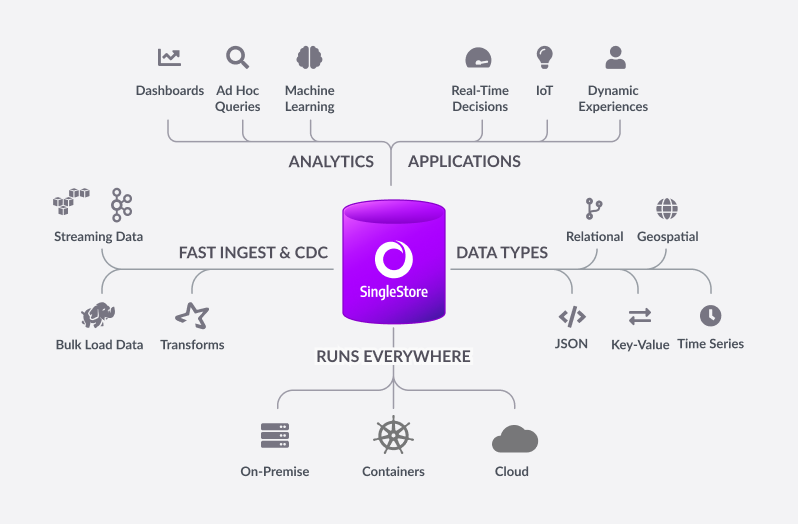
Before I get into the details of the paper, I suspect there might be a few readers who have yet to hear about SingleStore or know about some of its great features, so let’s start there. Built for developers and architects, SingleStoreDB is based on a distributed SQL architecture, delivering 10–100 millisecond performance on complex queries—all while ensuring that your organization can effortlessly scale. Now let’s go a bit deeper….
The SingleStoreDB :
- Scales horizontally providing high throughput across a wide range of platforms.
- Maintains a broad compatibility with common technologies in the modern data processing ecosystem (for example, orchestration platforms, developer IDEs, and BI tools), so you can easily integrate it in your existing environment.
- Features an in-memory rowstore and an on-disk columnstore to handle both highly concurrent operational and analytical workloads.
- Features the SingleStore Pipelines data ingestion technology that streams large amounts of data at high throughput into the database with exactly once semantics.
This means that you can continue to run your traditional SQL queries against your every growing data, which all resides on a distributed system, and you can do it fast. This is a big win for organizations who have active data growth in their environment.
What makes this even better is the ability of PowerFlex to scale from a few nodes to thousands. This provides a few different options to match your growing needs. You can start with just your SingleStore system deployed on PowerFlex and migrate other workloads on to the PowerFlex environment as time permits. This allows you to focus on just your database environment to start and then, as infrastructure comes up for renewal, you migrate those workloads and scale up your environment with more compute and storage capacity.
Or maybe you are making a bigger contribution to that 463 exabytes of data per day I mentioned earlier, and you need to scale out your environment to handle your data’s growth. You can do that too!
That’s the great thing about PowerFlex, you can consume resources independently of each other. You can add more storage or compute as you need them.
Additionally, with PowerFlex, you can deliver bare-metal and virtualized environments without having to choose only one. That’s right—you can run bare-metal servers right next to virtualized workloads.
Architecture
The way the engineers built this environment was using PowerFlex deployed in a hyper-converged infrastructure (HCI) configuration where the compute nodes are also storage nodes. (PowerFlex supports both two-tier architectures and HCI.)
As shown in the following diagram, our engineering team used five Dell PowerEdge R640 servers with dual CPUs, 384 GB of RAM, and eight SSDs per node. These five nodes were configured as HCI nodes and connected with a 25 Gbps network. The storage from across the nodes is aggregated to create a large software-defined pool of storage as a single protection domain that provides volumes to the SingleStore VMs. This is ideal for even the most demanding databases due to its high I/O capability.
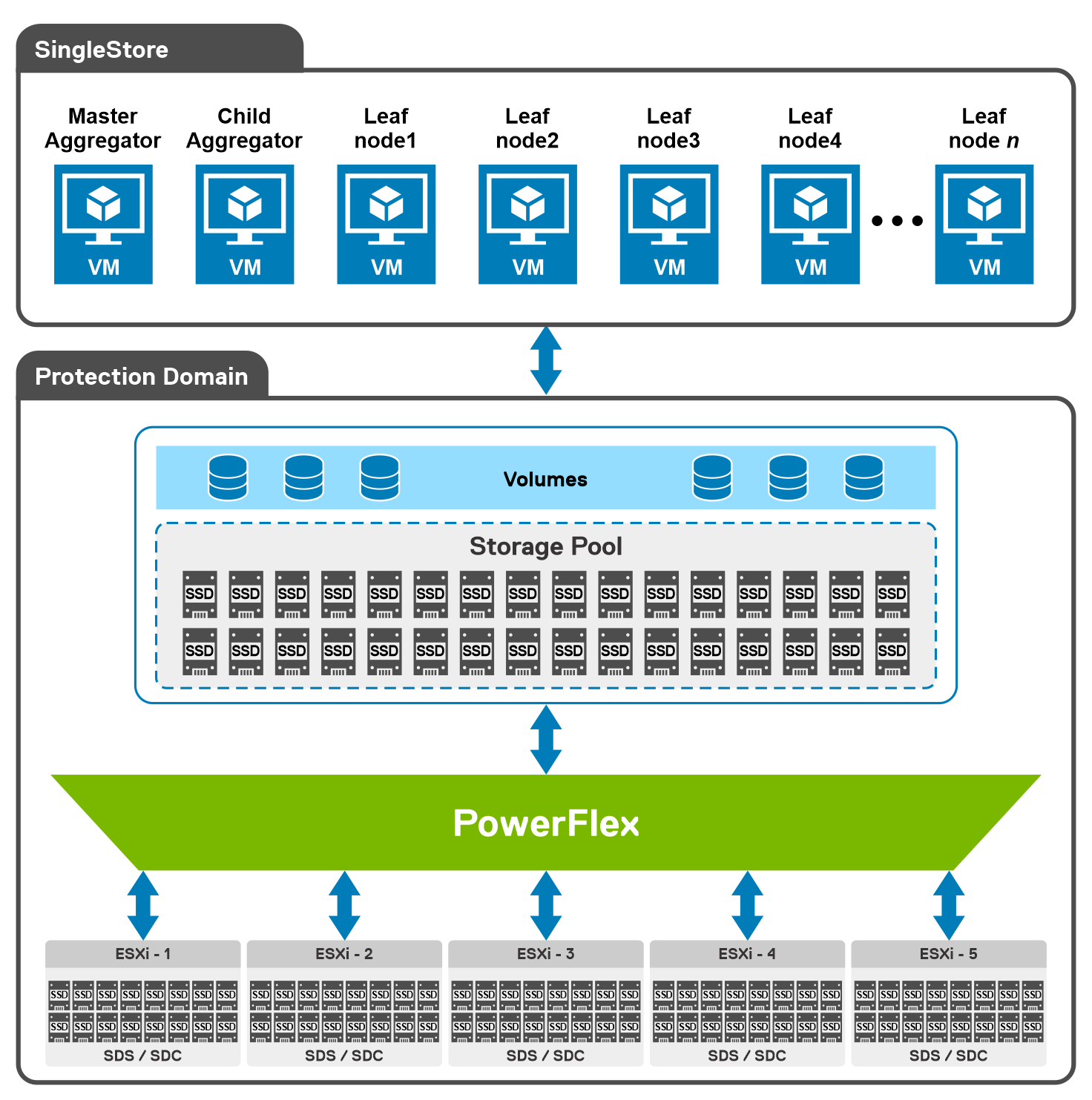
For this validation, the SingleStore Cluster VMs consist of two aggregator VMs and multiple leaf VMs. The white paper details the configuration of these VMs.
Additionally, the white paper provides an overview of the steps used to deploy SingleStore on VMware vSphere in a PowerFlex environment. For this validation, they followed the online user interface method to deploy SingleStore.
Testing
With the environment configured, the white paper then discusses how to validate the environment using TPC-DS. This tool provides 99 different queries that can be used to test a database. For this validation, only 95 of the 99 were used. The paper then describes both how the sample data set was created and how the tests were run.
The validation tests were run on 4, 6, and 8 leaf node configurations. This was done to understand the variation in performance as the environment scales. The testing showed that having more SingleStore leaf nodes results in better performance outcomes.
The testing also showed that there were no storage bottlenecks for the TPC-DS like workload and that using more powerful CPUs could further enhance the environment.
The white paper shows how SingleStore and PowerFlex can be used to create a dynamic and robust environment for your growing data needs as you do your part to contribute to the 463 exabytes of data that is expected to be created daily by 2025. To find out more about this design, contact your Dell representative.
Resources
Author: Tony Foster
Twitter: @wonder_nerd
LinkedIn

How PowerFlex Transforms Big Data with VMware Greenplum
Tue, 01 Nov 2022 21:18:15 -0000
|Read Time: 0 minutes
Quick! The word has just come down. There is a new initiative that requires a massively parallel processing (MPP) database, and you are in charge of implementing it. What are you going to do? Luckily, you know the answer. You also just discovered that the Dell PowerFlex Solutions team has you covered with a solutions guide for VMware Greenplum.
What is in the solutions guide and how will it help with an MPP database? This blog provides the answer. We look at what Greenplum is and how to leverage Dell PowerFlex for both the storage and compute resources in Greenplum.
Infrastructure flexibility: PowerFlex
If you have read my other blogs or are familiar with PowerFlex, you know it has powerful transmorphic properties. For example, PowerFlex nodes sometimes function as both storage and compute, like hyperconverged infrastructure (HCI). At other times, PowerFlex functions as a storage-only (SO) node or a compute-only (CO) node. Even more interesting, these node types can be mixed and matched in the same environment to meet the needs of the organization and the workloads that they run.
This transmorphic property of PowerFlex is helpful in a Greenplum deployment, especially with the configuration described in the solutions guide. Because the deployment is built on open-source PostgreSQL, it is optimized for the needs of an MPP database, like Greenplum. PowerFlex can deliver the compute performance necessary to support massive data IO with its CO nodes. The PowerFlex infrastructure can also support workloads running on CO nodes or nodes that combine compute and storage (hybrid nodes). By leveraging the malleable nature of PowerFlex, no additional silos are needed in the data center, and it may even help remove existing ones.
The architecture used in the solutions guide consists of 12 CO nodes and 10 SO nodes. The CO nodes have VMware ESXi installed on them, with Greenplum instances deployed on top. There are 10 segments and one director deployed for the Greenplum environment. The 12th CO node is used for redundancy.
The storage tier uses the 10 SO nodes to deliver 12 volumes backed by SSDs. This configuration creates a high speed, highly redundant storage system that is needed for Greenplum. Also, two protection domains are used to provide both primary and mirror storage for the Greenplum instances. Greenplum mirrors the volumes between those protection domains, adding an additional level of protection to the environment, as shown in the following figure:
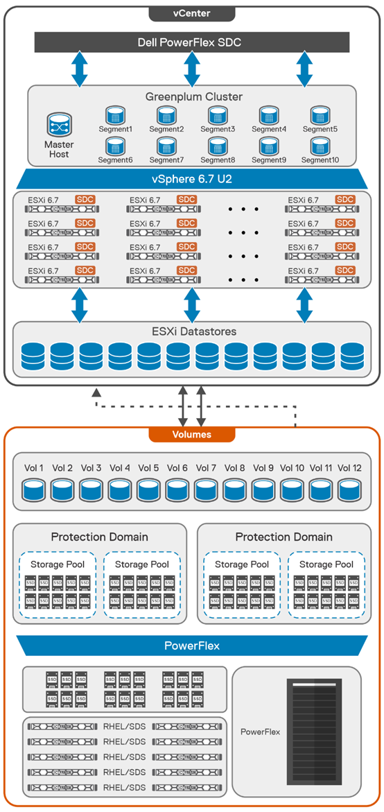
By using this fluid and composable architecture, the components can be scaled independently of one another, allowing for storage to be increased either independently or together with compute. Administrators can use this configuration to optimize usage and deliver appropriate resources as needed without creating silos in the environment.
Testing and validation with Greenplum: we have you covered
The solutions guide not only describes how to build a Greenplum environment, it also addresses testing, which many administrators want to perform before they finish a build. The guide covers performing basic validations with FIO and gpcheckperf. In the simplest terms, these tools ensure that IO, memory, and network performance are acceptable. The FIO tests that were run for the guide showed that the HBA was fully saturated, maximizing both read and write operations. The gpcheckperf testing showed a performance of 14,283.62 MB/sec for write workloads.
Wouldn’t you feel better if a Greenplum environment was tested with a real-world dataset? That is, taking it beyond just the minimum, maximum, and average numbers? The great news is that the architecture was tested that way! Our Dell Digital team has developed an internal test suite running static benchmarked data. This test suite is used at Dell Technologies across new Greenplum environments as the gold standard for new deployments.
In this test design, all the datasets and queries are static. This scenario allows for a consistent measurement of the environment from one run to the next. It also provides a baseline of an environment that can be used over time to see how its performance has changed -- for example, if the environment sped up or slowed down following a software update.
Massive performance with real data
So how did the architecture fare? It did very well! When 182 parallel complex queries were run simultaneously to stress the system, it took just under 12 minutes for the test to run. In that time, the environment had a read bandwidth of 40 GB/s and a write bandwidth of 10 GB/s. These results are using actual production-based queries from the Dell Digital team workload. These results are close to saturating the network bandwidth for the environment, which indicates that there are no storage bottlenecks.
The design covered in this solution guide goes beyond simply verifying that the environment can handle the workload; it also shows how the configuration can maintain performance during ongoing operations.
Maintaining performance with snapshots
One of the key areas that we tested was the impact of snapshots on performance. Snapshots are a frequent operation in data centers and are used to create test copies of data as well as a source for backups. For this reason, consider the impact of snapshots on MPP databases when looking at an environment, not just how fast the database performs when it is first deployed.
In our testing, we used the native snapshot capabilities of PowerFlex to measure the impact that snapshots have on performance. Using PowerFlex snapshots provides significant flexibility in data protection and cloning operations that are commonly performed in data centers.
We found that when the first storage-consistent snapshot of the database volumes was taken, the test took 45 seconds longer to complete than initial tests. This result was because it was the first snapshot of the volumes. Follow-on snapshots during testing resulted in minimal impact to the environment. This minimal impact is significant for MPP databases in which performance is important. (Of course, performance can vary with each deployment.)
We hope that these findings help administrators who are building a Greenplum environment feel more at ease. You not only have a solution guide to refer to as you architect the environment, you can be confident that it was built on best-in-class infrastructure and validated using common testing tools and real-world queries.
The bottom line
Now that you know the assignment is coming to build an MPP database using VMware Greenplum -- are you up to the challenge?
If you are, be sure to read the solution guide. If you need additional guidance on building your Greenplum environment on PowerFlex, be sure to reach out to your Dell representative.
Resources
Authors:
- Tony Foster – Dell Technologies, Twitter: @wonder_nerd
LinkedIn - Sue Mosovich – VMware

Introducing NVMe over TCP (NVMe/TCP) in PowerFlex 4.0
Fri, 26 Aug 2022 18:59:38 -0000
|Read Time: 0 minutes
Anyone who has used or managed PowerFlex knows that an environment is built from three lightweight software components: the MDM, the SDS, and the SDC. To deploy a PowerFlex environment, the typical steps are:
- Deploy an MDM management cluster
- Create a cluster of storage servers by installing and configuring the SDS software component
- Add Protection Domains and Storage Pools
- Install the SDC onto client systems
- Provision volumes and away you go!!*
*No requirement for multipath software, this is all handled by the SDC/SDS
There have been additions to this over the years, such as an SDR component for replication and the configuration of NVDIMM devices to create finegranularity storage pools that provide compression. Also added are PowerFlex rack and appliance environments. This is all automated with PowerFlex Manager. Fundamentally, the process involves the basic steps outlined above.
So, the question is why would we want to change anything from an elegant solution that is so simple?
This is due to where the SDC component ‘lives’ in the operating system or hypervisor hosting the application layer. Referring to the diagram below, it shows that the SDC must be installed in the kernel of the operating system or hypervisor, meaning that the SDC and the kernel must be compatible. Also the SDC component must be installed and maintained, it does not just ‘exist’.
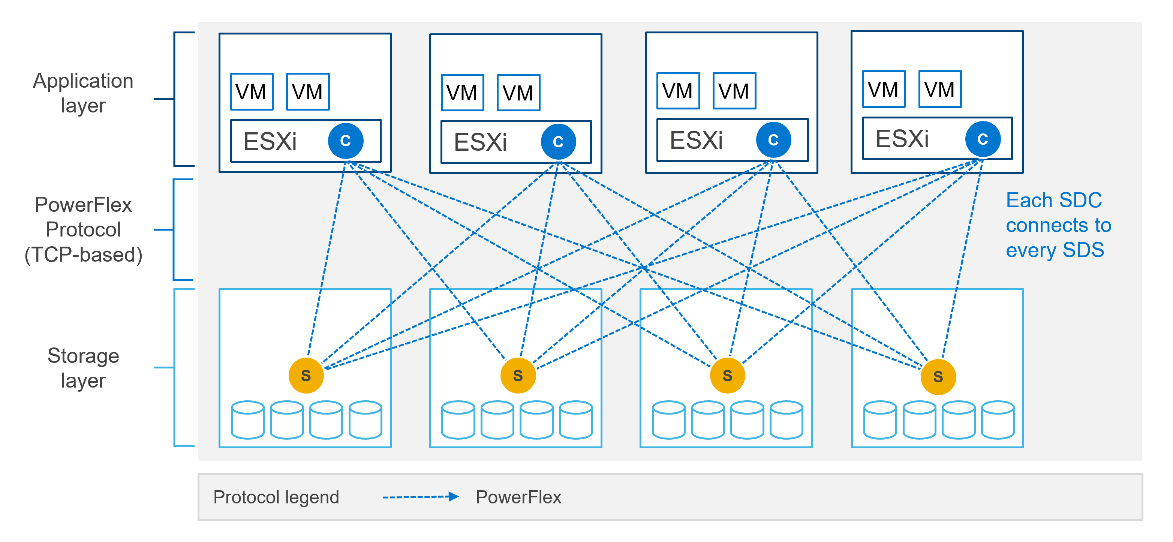
In most cases, this is fine and there are no issues whatsoever. The PowerFlex development team keeps the SDC current with all the major operating system versions and customers are happy to update the SDC within their environment when new versions become available.
There are, however, certain cases where manual deployment and management of the SDC causes significant overhead. There are also some edge use cases where there is no SDC available for specific operating systems. This is why the PowerFlex team has investigated alternatives.
In recent years, the use of Non-Volatile Memory Express (NVMe) has become pervasive within the storage industry. It is seen as the natural replacement to SCSI, due to its simplified command structure and its ability to provide multiple queues to devices, aligning perfectly with modern multi-core processors to provide very high performance.
NVMe appeared initially as a connection directly to disks within a server over a PCIe connection, progressing to being used over a variety of fabric interconnects.
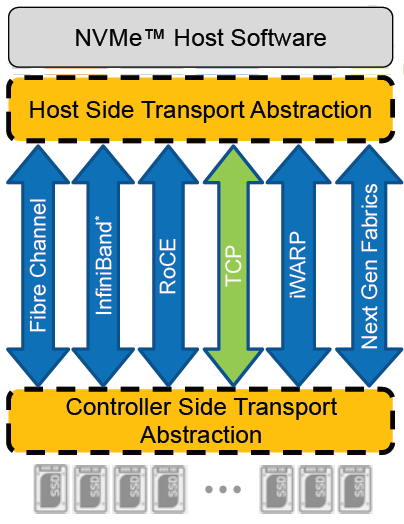
Added to this is the widespread support for NVMe/TCP across numerous operating system and hypervisor vendors. Most include support natively in their kernels.
There have been several announcements by Dell Technologies over the past months highlighting NVMe/TCP as an alternative interconnect to iSCSI across several of the storage platforms within the portfolio. It is therefore a natural progression for PowerFlex to also provide support for NVMe/TCP, particularly because it already uses a TCP-based interconnect.
PowerFlex implements support for NVMe/TCP with the introduction of a new component installed in the storage layer called the SDT.
The SDT is installed at the storage layer. The NVMe initiator in the operating system or hypervisor communicates with the SDT, which then communicates with the SDS. The NVMe initiator is part of the kernel of the operating system or hypervisor.
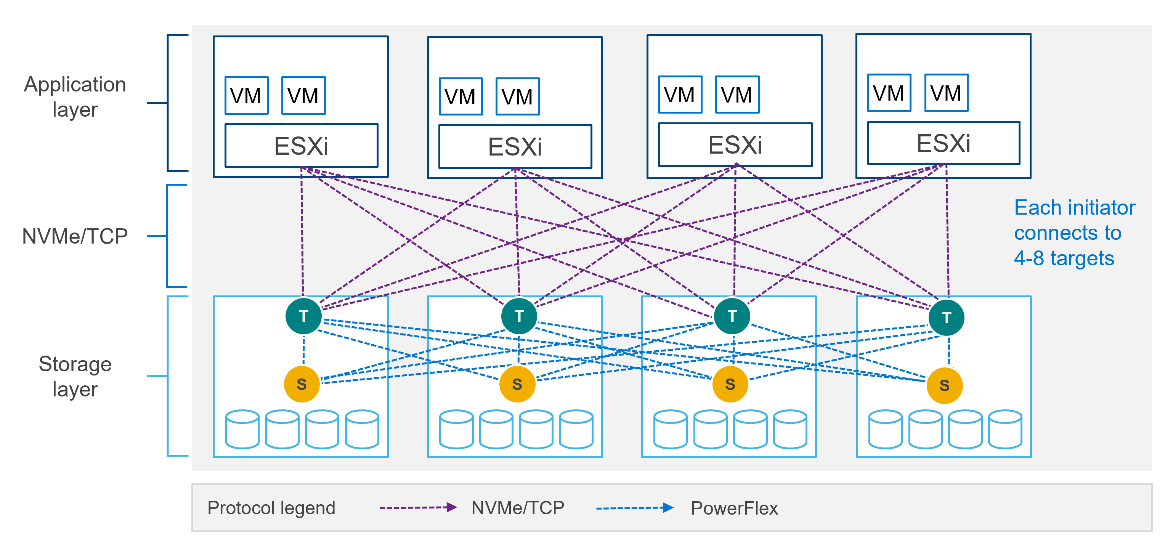
Of course, because PowerFlex is so ‘flexible,’ both connection methods (SDC and NVMe/TCP) are supported at the same time. The only limitation is that a volume can only be presented using one protocol or the other.
For the initial PowerFlex 4.0 release, the VMware ESXi hypervisor is supported. This support starts with ESXi 7.0 U3f. Support for Linux TCP initiators is currently in “tech preview” as the initiators continue to grow and mature, allowing for all failure cases to be accounted for.
NVMe/TCP is a very powerful solution for the workloads that take advantage of it. If you are interested in discovering more about how PowerFlex can enhance your datacenter, reach out to your Dell representative.
Authors:
Kevin M Jones, PowerFlex Engineering Technologist.
Tony Foster, Senior Principal Technical Marketing Engineer.
Twitter: @wonder_nerd
LinkedIn

An Introduction to the Unified PowerFlex Manager Platform
Tue, 16 Aug 2022 14:56:28 -0000
|Read Time: 0 minutes
We have all heard the well-known quote that “Change is the only constant in life”. Nowhere is this concept more apparent than in the world of IT, where digital transformation has become accepted as a fact of life and standing still is not an option. Anyone - or anything - that stands still in the world of IT faces becoming extinct, or irrelevant, when faced with responding to the ever-changing challenges that businesses must solve to survive and grow in the 21st Century. IT infrastructure has had to evolve to provide the answers needed in today’s business landscape – a world where Dev Ops and automation is driving business agility and productivity, where flexibility is key, and where consolidation and optimization are essential in the face of ever-shrinking budgets.
When dealing with the ever-changing IT landscape, software-defined infrastructure is ideally suited to delivering answers for business change. Indeed, many Dell Technologies customers choose PowerFlex as their software-defined infrastructure solution of choice because as a product, it has changed and evolved as much as customers themselves have had to change and evolve.
However, there are times when evolution itself is not enough to bring about inevitable changes that must occur - sometimes there must be a revolution! When it comes to IT infrastructure, managers are often given the “coin toss” of only being able to pick from either evolution or revolution. Faced with such a decision, managers often choose evolution over revolution – a simpler, more palatable path.
This was the dilemma that PowerFlex developers faced – continue with various separate management planes or unify them. Our developers were already planning to introduce several new features in PowerFlex 4.0, including PowerFlex File Services and NVMe/TCP connectivity. Adding new features to existing products generally means having to change the existing management tools and user interfaces to integrate the new functionality into the existing toolset. PowerFlex has a broad product portfolio and a broad set of management tools to match, as shown in the following figure. The uptake of customers using PowerFlex Manager was proof-positive that customers liked to use automation tools to simplify their infrastructure deployments and de-risk life-cycle management (LCM) tasks.
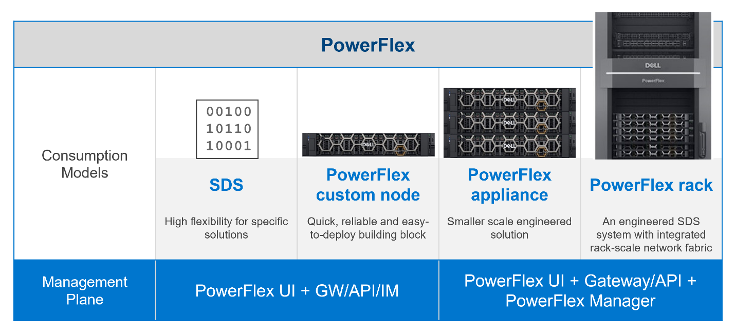
Figure 1: PowerFlex management planes, before PowerFlex 4.0
In addition to the multiple demands they had to contend with, the PowerFlex team was aware that new, as-yet unthought of demands would inevitably come to the surface in the future, as the onward progression of IT transformation continues.
Aiming to enhance the hybrid datacenter infrastructure that our customers are gravitating towards, simply evolving the existing management planes was not going to be sufficient. The time had come for revolution instead of evolution for the world of PowerFlex management.
The answer is simple to state, but not easy to achieve – design a new Management & Orchestration platform that reduces complexity for our customers. The goal was to simplify things by having a single management plane that is suitable for all customers, regardless of their consumption model. Revolution indeed!
Given a blank drawing board, the PowerFlex Team drew up a list of requirements needed for the new PowerFlex Management stack. The following is a simplified list:
- Unified RBAC and User Management. Implement single sign-on for authentication and authorization, ensuring that only a single set of roles is needed throughout PowerFlex.
- Have a single, unified web UI – but make it extensible, so that as new functionality becomes available, it can easily be added to the UI without breaking it. The addition of “PowerFlex File Services” with PowerFlex 4.0 is proof that this approach works!
- Create a single REST endpoint for all APIs, to ensure that both the legacy and the modern endpoints are accessible through a standardized PowerAPI.
- Ensure that the management stack is highly available, self-healing, and resilient.
- Centralize all events from all PowerFlex components – the SDS itself, switches, nodes, and resources, so that it simplifies the generation of alerts and call home operations.
Faced with this wish list, the team decided to build a new “unified” PowerFlex Manager to satisfy the “one management pane” requirement. But how to deliver a UI that is flexible enough to deal with serving different applications from a single web UI? How can this support a highly available and extensible management platform? It became clear to all that a new M&O stack was needed to achieve these aims and that the answer was to leverage the use of microservices, running as part of a larger, containerized platform.
Around the same time, the Dell ISG Development Team had been working internally on a new shared services platform. It was now ready for primetime. This Dell-developed Kubernetes distribution provides internal shared services that are required by nearly any IT infrastructure: logging services, database-as-a-service, certificate management, identity management, secrets management. It also manages Docker and Helm registries.
Using this new platform as a base, the PowerFlex Team then deployed additional microservices on top of it to micro-manage services specific to PowerFlex. Different micro-frontends can be called upon, depending on the operational context. While the overall PowerFlex Manager GUI application can be run as one “generic” UI, it can call out to different micro-frontends when required. This means that implementing and using microservices simplifies the transfer of previous element managers into the unified PowerFlex Manager world. For example, the traditional PowerFlex Block UI (the PowerFlex Presentation Server UI from PowerFlex 3.6) is now treated as one microservice, while the PowerFlex Manager Lifecycle Manager is now handled by several microservices all working in tandem. Plus, it becomes simple to add a new micro-frontend to handle the “PowerFlex File” functionality that has been released with PowerFlex 4.0 into the GUI as well. Because each GUI section now has its own micro-frontend, the UI now meets the “flexible and extensible” requirement.
This flexibility gives our existing PowerFlex customers assurance as they move from version 3.6 to 4.0. And equally important, it means there is now a single unified manager that can cover all consumption models, as shown in the following figure:
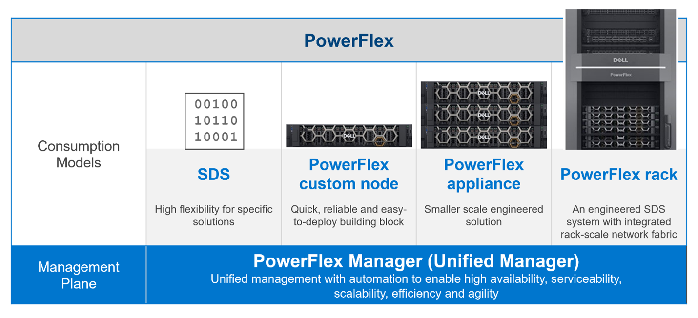
Figure 2. The unified PowerFlex Management Plane with PowerFlex 4.0
Finally, what does the new unified PowerFlex Manager look like? Existing PowerFlex users will be pleased to see that the new unified PowerFlex Manager still has the same “look and feel” that PowerFlex Manager 3.x had. We hope this will make it easier for operations staff when they decide to upgrade from PowerFlex 3.x to PowerFlex 4.0. The following figures show the Block and File Services tabs respectively:
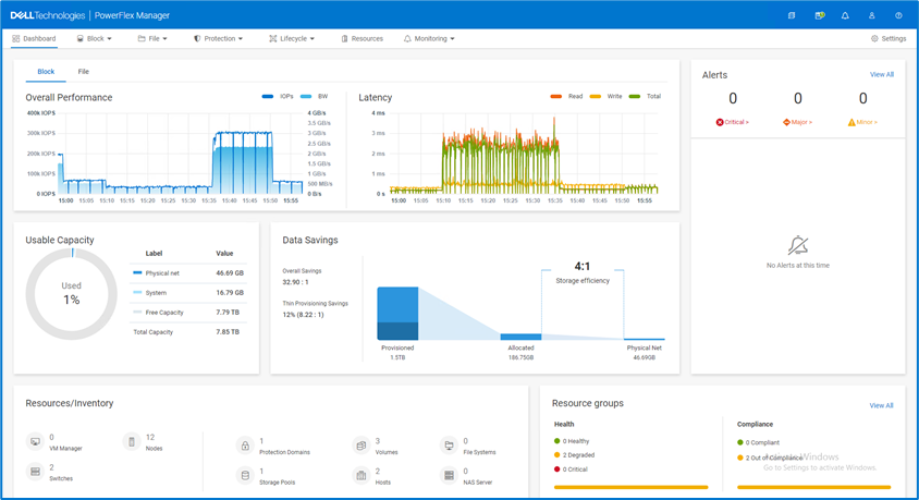
Figure 3. The unified PowerFlex Manager 4.0 Dashboard

Figure 4. The unified PowerFlex Manager 4.0 – Resources
While we cannot stop progress, we can always excel when faced with an ever-changing landscape. Customers already choose PowerFlex when they want to deploy highly performant, scalable, resilient, and flexible software-defined infrastructures. They can now also choose to move to PowerFlex 4.0, safe in the knowledge that they have also future-proofed the management of their infrastructure. While they may not know what changes are in store, the unified PowerFlex Manager Platform will help ensure that those future changes, whatever they are, can be handled easily when deployed on top of PowerFlex.
The enhancements made to PowerFlex provide many possibilities for modern datacenters and their administrators, especially when faced with the constant digital transformation seen in IT today. This is seen in how the various PowerFlex management consoles have been unified to allow continued change and growth to meet organizations’ needs. Yet, there is also continuity with previous versions of the UI, ensuring an easy transition for users when they have migrated to 4.0. If you are interested in finding out more about PowerFlex and all it has to offer your organization, reach out to your Dell representative.
Authors: Simon Stevens, PowerFlex Engineering Technologist, EMEA.
Tony Foster, Senior Principal Technical Marketing Engineer.
Twitter: @wonder_nerd
LinkedIn

New File Services Capabilities of PowerFlex 4.0
Tue, 16 Aug 2022 14:56:28 -0000
|Read Time: 0 minutes
“Just file it,” they say, and your obvious question is “where?” One of the new features introduced in PowerFlex 4.0 is file services. Which means that you can file it in PowerFlex. In this blog we’ll dig into the new file service capabilities offered with 4.0 and how they can benefit your organization.
I know that when I think of file services, I think back to the late 90s and early 2000s when most organizations had a Microsoft Windows NT box or two in the rack that provided a centralized location on the network for file storage. Often it was known as “cheap and deep storage,” because you bought the biggest cheapest drives you could to install in that server with RAID 5 protection. After all, most of the time it was user files that were being worked on and folks already had a copy saved to their desktop. The file share didn’t have to be fast or responsive, and the biggest concern of the day was using up all the space on those massive 146 GB drives!
That was then … today file services do so much more. They need to be responsive, reliable, and agile to handle not only the traditional shared files, but also the other things that are now stored on file shares.
The most common thing people think about is user data from VDI instances. All the files that make up a user’s desktop, from the background image to the documents, to the customization of folders, all these things and more are traditionally stored in a file share when using instant clones.
PowerFlex can also handle powerful, high performance workload scenarios such as image classification and training. This is because of the storage backend. It is possible to rapidly serve files to training nodes and other high performance processing systems. The storage calls can go to the first available storage node, reducing file recall times. This of course extends to other high speed file workloads as well.
Beyond rapid recall times, PowerFlex provides massive performance, with 6-nines of availability1, and native multi-pathing. This is a big deal for modern file workloads. With VDI alone you need all of these things. If your file storage system can’t deliver them, you could be looking at poor user experience or worse: users who can’t work. I know, that’s a scary thought and PowerFlex can help significantly lessen those fears.
In addition to the performance, you can manage the file servers in the same PowerFlex UI as the rest of your PowerFlex environment. This means there is no need to learn a new UI, or bounce all over to set up a CIFS share—it’s all at your fingertips. In the UI it’s as simple as changing the tab to go from block to file on many screens.
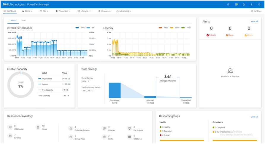
The PowerFlex file controllers (physical) host the software for the NAS servers (logical). You start with two file controllers and can grow to 16 file controllers. Having various sizes of file controllers allows you to customize performance to meet your environment’s needs. The NAS Servers are containerized logical segmentations that provide the file services to the clients, and you can have up to 512 in a cluster. They are responsible for namespaces, security policies, and serving file systems to the clients.
Each of the file volumes that are provided by the file services are backed by PowerFlex volumes. This means that you can increase file service performance and capacity by adding PowerFlex nodes to the storage layer just like a traditional block storage instance. This allows you to independently scale performance and capacity, based on your needs.
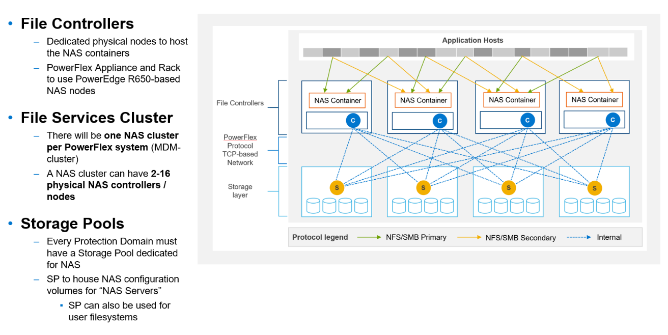
The following table provides some of the other specs you might be wondering about.
Feature | Max |
FS Capacity | 256 TB |
Max file size | 64 TB |
# of files | 10 billion |
# of ACLs | 4 million |
User File Systems | 4096 |
Snaps per File System | 126 |
CIFS | 160000 |
NFS exports | 80000 |
Beyond the architectural goodness, file storage is something that can be added later to a PowerFlex environment. Thus, you aren’t forced to get something now because you “might” need it later. You can implement it when that project starts or when you’re ready to migrate off that single use file server. You can also grow it as you need, by starting small and growing to a large deployment with hundreds of namespaces and thousands of file systems.
With PowerFlex when someone says “file it,” you’ll know you have the capacity to support that file and many more. PowerFlex file services provide the capability to deliver the power needed for even the most demanding file-based workloads like VDI and AI/ML data classification systems. It’s as easy managing the environment as it is integrated into the UI.
If you are interested in finding out more about PowerFlex file services, contact your Dell representative.
Author: Tony Foster
Twitter: @wonder_nerd
LinkedIn
1 Workload performance claims based on internal Dell testing. (Source: IDC Business Value Snapshot for PowerFlex – 2020.)

Dell PowerFlex Bare Metal with Amazon Elastic Kubernetes Service Anywhere, and We Do Mean “Anywhere!”
Mon, 18 Jul 2022 15:52:39 -0000
|Read Time: 0 minutes
Anywhere, that’s a powerful statement, especially to someone who works in IT. That could be in a cloud, or in a set of virtual machines in your data center, or even physical hosts. What if you could run Amazon Elastic Kubernetes Service (EKS) Anywhere on a virtual machine or on bare-metal, anywhere, including your data center?
You might have read my previous blog where we discussed running Amazon EKS Anywhere on Dell PowerFlex in a virtual environment. This time we are going further and have validated Amazon EKS Anywhere on a bare-metal instance of PowerFlex.
The good old days
If you are old enough to remember, like I am, the days before virtualization, with stranded resources and data centers with enormous footprints to support all the discrete servers and siloed workloads, you might be curious: Why would anyone go back to bare-metal?
Having been part of the movement all the way back to 2006, it’s a good question. In simple terms, what we are seeing today is not a return to the bare-metal siloed data centers of 20 years ago. Instead, we are seeing an improved utilization of resources by leveraging micro services, be that in the cloud, in virtualized environments, or with bare-metal. In addition, it provides greater portability and scalability than could ever have been imagined 20 years ago. This is thanks to the use of containers and the way they isolate processes from each other. Additionally, with a bare-metal platform running containers, more system resources can be directed to workloads than if the containers were nested inside of a virtual environment.
This is central to the concept of a DevOps-ready platform. In the coming weeks, we will expand on how this enhances the productivity of native cloud operations for today’s modern businesses. You will find this on the Dell Digital blog with the title Customer Choice Comes First: Dell Technologies and AWS EKS Anywhere.
Beyond just the economics of this, there are scenarios where a bare-metal deployment can be helpful. This includes low latency and latency sensitive applications that need to run near the data origin. This of course can include edge scenarios where it is not practical to transmit vast quantities of data.
Data sovereignty and compliance can also be addressed as an Amazon EKS Anywhere solution. While data and associated processing can be done in the data center, to maintain compliance requirements, it can still be part of a holistic environment that is displayed in the Amazon EKS Console when the Amazon EKS Connector has been configured. This allows for monitoring of applications running anywhere in the environment.
Digging deeper
Digging deeper on this concept, PowerFlex is a software defined infrastructure (SDI) that provides a powerful tool in delivering the modern bare-metal or virtualized options that best suit application deployment needs. The hardware infrastructure becomes malleable to the needs of the data center and can take on various forms of modern infrastructure, from hyper-converged to bare-metal. This has always been a core tenet of PowerFlex.
When Amazon EKS Anywhere is deployed on PowerFlex, it becomes possible to optimize the IT environment precisely for the needs of the environment, instead of forcing it to conform to the limits of IT infrastructure. Bare-metal hosts can provide microservices for large applications, such as databases and websites, where a container instance may be created and destroyed rapidly and on a massive scale.
The architecture
Let’s look at the Amazon EKS Anywhere validated architecture in the following figure. It shows how PowerFlex delivers a unique software-defined 3-tier architecture that can asymmetrically scale compute separate from storage.
The bottom portion of the figure consists of PowerFlex – storage-only nodes (1U). In the middle of the diagram are the hosts used for the control plane and worker nodes. These are PowerFlex – compute-only nodes (2U). On the far left are the admin and Tinkerbell nodes that allow for administration of the environment. Lastly, in the top set of boxes, we have the control plane, at the top left, that provides operational control and orchestration. The worker nodes, at the top right, handle the workloads.
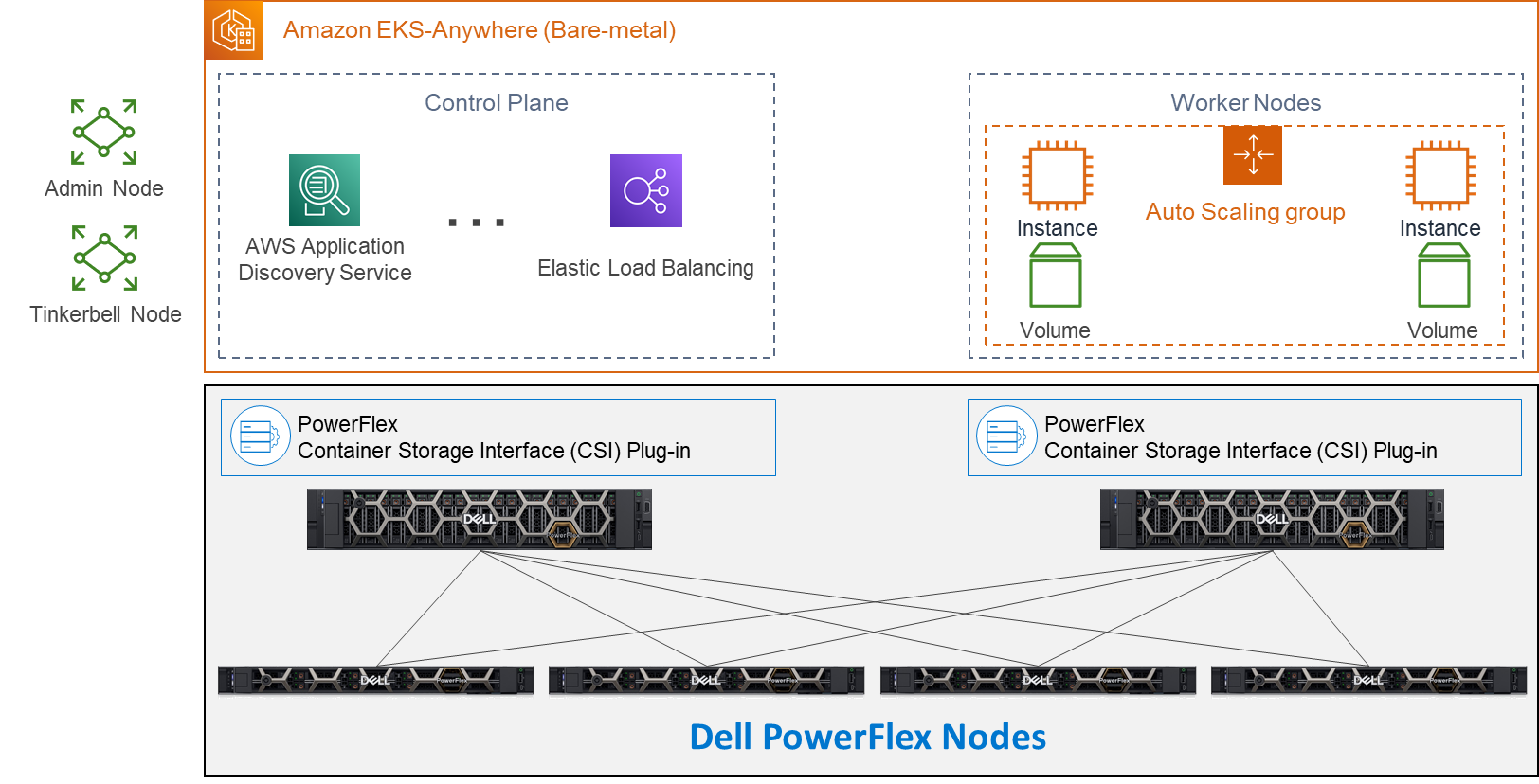
Let’s look at some important aspects of each area shown here, starting with the storage nodes. Each storage node contains five 1.4TB SAS SSD drives and eight 25GbE network links. For the validation, as shown here, four PowerFlex storage nodes were used to provide full redundancy.
For the compute nodes, we used two 2U nodes. These two hosts have the PowerFlex Container Storage Interface (CSI) Plug-in installed to provide access to the PowerFlex storage. This is deployed as part of the PXE boot process along with the Ubuntu OS. It’s important to note that there is no hypervisor installed and that the storage is provided by the four storage nodes. This creates a two-layer architecture which, as you can see, creates separate storage and compute layers for the environment.
Using a two-layer architecture makes it possible to scale resources independently as needed in the environment, which allows for optimal resource utilization. Thus, if more storage is needed, it can be scaled without increasing the amount of compute. And likewise, if the environment needs additional compute capacity, it can easily be added.
Cluster Creation
Outside of the Amazon EKS Anywhere instance are two nodes. Both are central to building the control plane and worker nodes. The admin node is where the user can control the Amazon EKS Anywhere instance and serves as a portal to upload inventory information to the Tinkerbell node. The Tinkerbell node serves as the infrastructure services stack and is key in the provisioning and PXE booting of the bare-metal workloads.
When a configuration file with the data center hardware has been uploaded, Tinkerbell generates a cluster configuration file. The hardware configuration and cluster configuration files, both in YAML format, are processed by Tinkerbell to create a boot strap kind cluster on the admin host to install the Cluster-API (CAPI) and the Cluster-API-Provider-Tinkerbell (CAPT).
With the base control environment operational, CAPI creates cluster node resources, and CAPT maps and powers on the corresponding bare-mental servers. The bare-metal servers PXE boot from the Tinkerbell node. The bare-metal servers then join the Kubernetes cluster. Cluster management resources are transferred from the bootstrap cluster to the target Amazon EKS Anywhere workload cluster. The local bootstrap kind cluster is then deleted from the admin machine. This creates both the Control Plane and Worker Nodes. With the cluster established, SDC drivers are installed on the Worker node(s) along with the Dell CSI Plug-in for PowerFlex. At this point, workloads can be deployed to the Worker node(s) as needed.
Cluster Provisioning
With the infrastructure deployed, our solutions engineers were able to test the Amazon EKS Anywhere environment. The testing included provisioning persistent volume claims (PVCs), expanding PVCs, and snapshotting them. All of this functionality relies on the Dell CSI Plugin for PowerFlex. Following this validation, a test workload can be deployed on the bare-metal Amazon EKS Anywhere environment.
If you would like to explore the deployment further, the Dell Solutions Engineering team is creating a white paper on the deployment of Amazon EKS Anywhere that covers these details in greater depth. When published, we will be sure to update this blog with a link to the white paper.
Anywhere
This validation enables the use of Amazon EKS Anywhere across bare-metal environments, expanding the use beyond the previous validation of virtual environments. This means that you can use Amazon EKS Anywhere anywhere, really!
With bare-metal deployments, it is possible to scale environments independently based on resource demands. PowerFlex software defined infrastructure not only supports a malleable environment like this, but also allows mixing environments to include hyper converged components. This means that an infrastructure can be tailored to the environment’s needs — instead of the environment being forced to conform to the infrastructure. It also creates an environment that unifies the competing demands of data sovereignty and cloud IT, by enabling data to maintain appropriate residence while unifying the control plane.
If you’re interested in finding out more about how you can leverage Amazon EKS Anywhere in your bare-metal PowerFlex environment, reach out to your Dell representative. Where is anywhere for you?
Resources
- Deploying a test workload
- Amazon Elastic Kubernetes Service Anywhere on Dell PowerFlex
- Introducing bare metal deployments for Amazon EKS Anywhere
- Blog: Customer Choice Comes First: Dell Technologies and AWS EKS Anywhere
Authors: Tony Foster
Twitter: @wonder_nerd
LinkedIn
Syed Abrar LinkedIn

PowerFlex and PowerProtect: Keeping Your IT Kingdom Free of Ransomware
Wed, 13 Jul 2022 13:05:58 -0000
|Read Time: 0 minutes
“To be, or not to be? That is the question.” Sadly, the answer for many organizations is “to be” the victim of ransomware. In 2020, the Internet Crime Complaint Center (IC3), a department of the FBI, received “2,474 complaints identified as ransomware with adjusted losses of over $29.1 million” according to their annual report.
This report is just the tip of the iceberg. Some organizations choose not to report ransomware attacks and keep the attacks out of the news. Reporting an attack might cost more in negative publicity than quietly paying the ransom.
These perspectives make it appear that no one is immune to ransomware. However, if your organization is attacked, wouldn’t you prefer to avoid both the attention and paying a ransom for your data?
The Dell PowerFlex Solutions Engineering team developed a white paper to help make this dream come true for PowerFlex customers. They worked jointly with the Dell PowerProtect team to create a design that illustrates how to integrate Dell PowerProtect Cyber Recovery with PowerFlex. See Ransomware Protection: Secure Your Data on Dell PowerFlex with Dell PowerProtect Cyber Recovery.
The white paper shows how to use the Cyber Recovery solution with PowerFlex to thwart ransomware and other malicious attacks, protecting your kingdom from would-be attackers. This protection is accomplished by creating an air-gapped vault that can be used with other data protection strategies to mitigate the actions of bad actors. This configuration is shown in the following architectural diagram: 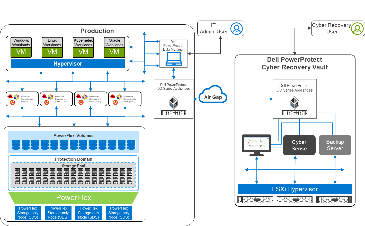
Figure 1: Architectural diagram
Air gaps and keeping the kingdom secure
The white paper describes a two-layer PowerFlex design in which the storage and compute environment are separate. The left side of the diagram shows the production environment. On the right side of the diagram, notice that there is a second environment, the Dell PowerProtect Cyber Recovery vault. The Cyber Recovery vault is a separate, logically air-gapped environment that helps to protect the production environment. The PowerProtect software runs on the Cyber Recovery vault and analyzes data from the production environment for signs of tampering, such as encryption of volumes or a large number of deletions.
The logical air gap between the two environments is only opened to replicate data from the production environment to the Cyber Recovery vault. Also, the connection between the two environments is only activated from the Cyber Recovery vault. I like to think of this scenario as a moat surrounding a castle with a drawbridge. The only way to cross the moat is over the drawbridge. The drawbridge is controlled from the castle—a secure location that is hard to breach. Likewise, the air gap makes it very difficult for intruders.
Separation of powers
Notice that there are two different users shown in the diagram: an Admin User and a Cyber Recovery User. This difference is important because many attacks can originate within the organization either knowingly or unknowingly, such as a spear phishing attack that targets IT. The division of powers and responsibilities makes it more difficult for a bad actor to compromise both users and get the keys to the kingdom. Therefore, the bad actor has a nearly impossible challenge disrupting both the production environment and the Cyber Recovery environment.
Protecting the kingdom
Let’s take a deeper look at the logical architecture used in the white paper. The design uses a pair of PowerProtect DD systems in which the data resides for both the production and vault sites. Replication between the two PowerProtect DD systems occurs over the logically air-gapped connection. Think of this replication of data as materials moving across the drawbridge to the castle. Material can arrive at the castle only when the gate house lowers the drawbridge.
The Cyber Recovery software is responsible for the synchronization of data and locking specified data copies. This software acts like the guards at the gate of the castle: they raise and lower the drawbridge and only allow so many carts into the castle at one time.
A backup server runs the Cyber Recovery software. The backup server supports various options to meet specific needs. Think of the backup server as the troops in a castle: there are the guards at the gate, archers on the walls, and all the other resources and activities that keep the castle safe. The type of troops varies depending on the size of the castle and the threat landscape. This scenario is also true of the backup server.
The Cyber Recovery environment also includes the CyberSense software, which is responsible for detecting signs of corruption caused by ransomware and similar threats. It uses machine learning (ML) to analyze the backup copies stored in the vault PowerProtect DD to look for signs of corruption. CyberSense detects corruption with a confidence level of up to 99.5 percent. Think of CyberSense as the trusted advisor to the castle: alerting the appropriate teams when an attack is imminent and allowing the castle to defend against attacks.
Putting it all together
In the following animation, we see a high-level overview of how the environment operates under normal conditions, during a ransomware attack, and during recovery. It shows content being replicated into the Cyber Recovery vault from the PowerFlex environment. We then see a bad actor attempt to compromise the VMs in the PowerFlex environment. CyberSense detects the attack and notifies the Cyber Recovery administrators. The administrators can then work with the production team to secure and restore the environment, thwarting the bad actor and the attempt to hold the organization hostage.
Figure 2: Animation of a ransomware attack and recovery
Beyond describing the architecture of this solution, the white paper shows how to deploy and configure both environments. Readers can take the next step towards building protection from a cyberattack.
The white paper is an excellent resource to learn more about protecting your kingdom from ransomware. To choose “not to be” a ransomware victim, contact your Dell representative for additional information.
Author: Tony Foster
Twitter: @wonder_nerd
LinkedIn
Expanding VxRail Dynamic Node Storage Options with PowerFlex
Wed, 09 Feb 2022 19:53:55 -0000
|Read Time: 0 minutes
It was recently announced that Dell VxRail dynamic nodes now supports Dell PowerFlex. This announcement expands the storage possibilities for VxRail dynamic nodes, providing a powerful and complimentary option for hyperconverged data centers. A white paper published by the Dell Technologies Solutions Engineering team details this configuration with VxRail dynamic nodes and PowerFlex.
In this blog we will explore how to use VxRail dynamic nodes with PowerFlex and explain why the two in combination are beneficial for organizations. We will begin by providing an overview for the dynamic nodes and PowerFlex, then describe why this duo is beneficial, and finally we will look at some of the exciting aspects of the white paper.
VxRail dynamic nodes and PowerFlex
VxRail
VxRail dynamic nodes are compute-only nodes, meaning these nodes don’t provide vSAN storage. They are available in the E, P, and V Series and accommodate a large variety of use cases. VxRail dynamic nodes rely on an external storage resource as their primary storage, which in this case is PowerFlex.
The following diagram shows a traditional VxRail environment is on the left. This environment uses VMware vSAN datastore for storage. The right side of the diagram is a VxRail dynamic node cluster. The VxRail dynamic nodes are compute only nodes, and, in this case rely on PowerFlex for storage. In this diagram the VxRail cluster, the VxRail dynamic node cluster, and the PowerFlex storage can all be scaled independently of one another for certain workloads. For example, some may want to adjust resources for Oracle environments to reduce license costs.
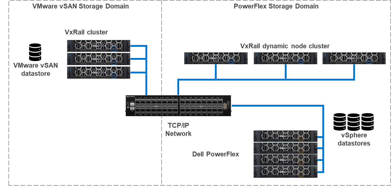
To learn more about VxRail dynamic nodes, see my colleague Daniel Chiu’s blog on the VxRail 7.0.240 release.
PowerFlex
PowerFlex is a software defined infrastructure that delivers linear scaling of performance and resources. PowerFlex is built on top of PowerEdge servers and aggregates the storage of four or more PowerFlex nodes to create a high-performance software defined storage system. PowerFlex uses a traditional TCP/IP network to connect nodes and deliver storage to environments. This is the only storage platform for VxRail dynamic nodes that uses an IP network. Both of these attributes are analogous to how VxRail delivers storage.
PowerFlex-VxRail benefits
If it seems confusing because VxRail and PowerFlex seem to share many of the same characteristics, it is they do share many of the same characteristics. However, this is why it also makes sense to bring them together. This section of this blog describes how the two can be combined to deliver a powerful architecture for certain applications.
The following diagram shows the logical configuration of PowerFlex and VxRail combined. Starting at the top of the diagram, you will see the VxRail cluster, consisting of four dynamic nodes. These dynamic nodes are running the PowerFlex Storage Data Client (SDC), a software-based storage adapter, which runs in the ESXi kernel. The SDC enables the VxRail dynamic nodes to consume volumes provisioned from the storage on the PowerFlex nodes.
In the lower half of the diagram, we see the PowerFlex nodes and the storage they present. The cluster contains four PowerFlex storage-only nodes. In these nodes, the internal drives are aggregated into a storage pool that spans across all four nodes. The storage pool capacity can then be provisioned as PowerFlex volumes to the VxRail dynamic nodes.
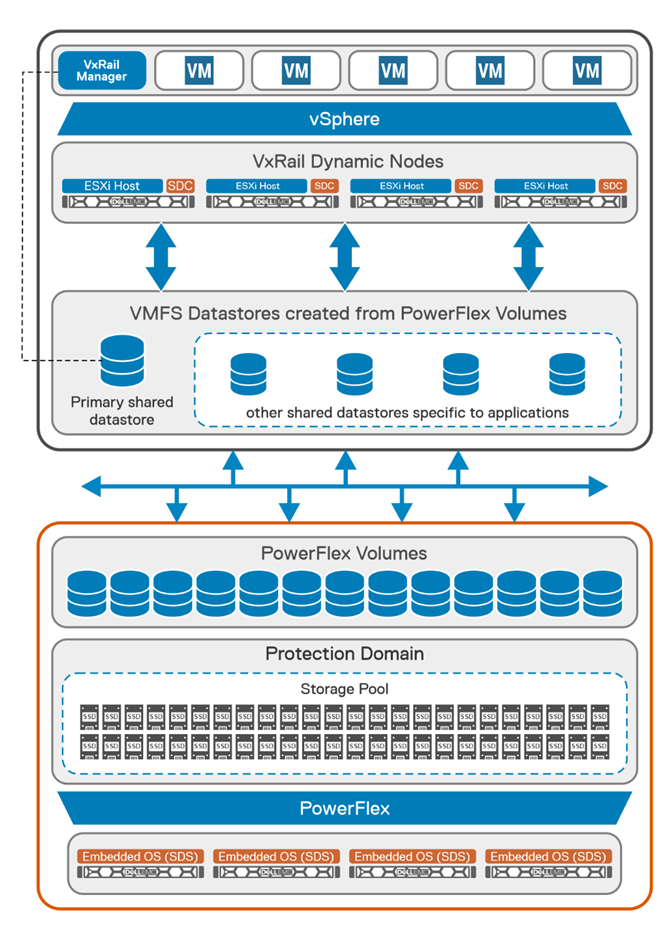
AI workloads offer a great example of where it makes perfect sense to bring these two technologies together. There has been a lot of buzz around virtualizing AI, ML, and HPC workloads. Dell, NVIDIA, and VMware have done amazing things in this area, including NVIDIA AI Enterprise on VxRail. Now you may think this does not matter to your organization, as there are no uses for AI, ML, or HPC in your organizations, but uses for AI are constantly evolving. For example, AI is even being used extensively in agriculture.
These new AI technologies are data driven and require massive amounts of data to train and validate models. This data needs to be stored somewhere, and the systems processing benefit from quick access to it and VxRail is awesome for that. There are exceptions, what if your data set is too large for VxRail, or what if you have multiple AI models that need to be shared amongst multiple clusters?
The typical response in this scenario is to get a storage array for the environment. That would work, except you’ve just added complexity to the environment. Many users move to HCI to drive complexity out of their environment. Fibre channel is a great example of this complexity.
To reduce complexity, there’s another option, just use PowerFlex. PowerFlex can support hundreds of nodes, enabling highly-performant storage needed for modern, data hungry applications. Additionally, it operates on standard TCP/IP networks, eliminating the need for a dedicated storage switch fabric. This makes it an ideal choice for virtualized AI workloads.
The idea of a standard network may be important to some organizations, due to the complexity aspects or they may not have the in-house talent to administer a Fibre channel network. This is particularly true in areas where administrators are hard to find. Leveraging the skills and resources already available within an organization, now more than ever, is extremely important.
Another area where PowerFlex backed VxRail dynamic nodes can be beneficial is with data services like data at rest encryption (D@RE). Both vSAN and PowerFlex support D@RE technology. When encryption is run on a host, the encryption/decryption process consumes resources. This impact can vary depending on the workload. If the workload has a lot of I/O, the resource utilization (CPU and RAM) could be more than a workload with lower I/O. When D@RE is offloaded, those resources needed for D@RE can be used for other tasks, such as workloads.
Beyond D@RE, PowerFlex has many other built in data resiliency and protection mechanisms. These include a distributed mesh mirroring system and native asynchronous replication. These functions help deliver fast data access and a consistent data protection strategy.
The impact of storage processing, like encryption, can impact the number of hosts that need to be licensed. Good examples of this are large databases with millions of transactions per minute (TPM). For each data write there is an encryption process. This process can be small and appear inconsequential, that is until you have millions of those processes happening in the same time span. This can cause a performance degradation if there aren’t enough resources to handle both the encryption processing and the CPU/RAM demands of the database environment and can lead to needing additional hosts to support the database environment.
In such a scenario, it can be advantageous to use VxRail dynamic nodes with PowerFlex. This offloads the encryption to PowerFlex allowing all the compute performance to be delivered to the VMs.
Dell PowerFlex with VxRail Dynamic Nodes – White Paper
The Solutions Engineering team has included many graphics detailing both the logical and physical design of how VxRail dynamic nodes can be configured with PowerFlex.
It highlights several important prerequisites, including that you will need to be using VxRail system software version 7.0.300 or above. This is important as this release is when support for PowerFlex was added to VxRail dynamic nodes. If the VxRail environment is not at the correct version, it could cause delays while the environment is upgraded to a compatible version.
Beyond just building an environment, the white paper also details administrating the environment. While administration is a relatively straight forward for seasoned administrators, it’s always good to have instructions in case an administrator is sick or other members of the team are gaining experience.
All of this and so much more are outlined in the white paper. If you are interested in all the details, be sure to read through it. This applies if your team is currently using VxRail and looking to add dynamic nodes or if you have both PowerFlex and VxRail in your environment and you want to expand the capabilities of each.
Summary
This blog provided an overview of VxRail dynamic nodes and how they can take advantage of PowerFlex software defined storage when needed. This includes reducing licensing costs and keeping complexity, like fiber channel, to a minimum in your environment. To find out more, read the white paper or talk with your Dell representative.
Author Information
Author: Tony Foster
Twitter: @wonder_nerd

PowerFlex and Amazon: Destination EKS Anywhere
Wed, 19 Jan 2022 17:09:54 -0000
|Read Time: 0 minutes
Welcome to your destination. Today Dell Technologies is pleased to share that Amazon Elastic Kubernetes Service (Amazon EKS) Anywhere has been validated on Dell PowerFlex software-defined infrastructure. Amazon EKS Anywhere is a new deployment option for Amazon EKS that enables customers to easily create and operate Kubernetes clusters on-premises while allowing for easy connectivity and portability to Amazon AWS environments. PowerFlex helps customers deliver a flexible deployment solution that scales as needs change with smooth, painless node-by-node expandability, inclusive of compute and storage, in a unified fabric architecture.
Dell Technologies collaborates with a broad ecosystem of public cloud providers to help our customers support multi-cloud environments that help place the right data and applications where it makes the most sense for them. Deploying Amazon EKS Anywhere on Dell Technologies infrastructure streamlines application development and delivery by allowing organizations to easily create and manage on premises Kubernetes clusters.
Across nearly all industries, IT organizations are moving to a more developer-oriented model that requires automated processes, rapid resource delivery, and reliable infrastructure. To drive operational simplicity through Kubernetes orchestration, Amazon EKS Anywhere helps customers automate cluster management, reduce support costs, and eliminate the redundant effort of using multiple open source or 3rd party tools to manage Kubernetes clusters. The combination of automated Kubernetes cluster management with intelligent, automated infrastructure quickly brings organizations to the next stop in their IT Journey, allowing them to provide infrastructure as code and empower their DevOps teams to be the innovation engine for their businesses.
Let us explore Amazon EKS Anywhere on PowerFlex and how it helps you move towards a more developer-oriented model. First, let’s look at the requirements for Amazon EKS Anywhere.
To deploy Amazon EKS Anywhere we will need a PowerFlex environment running VMware vSphere 7.0 or higher. Specifically, our validation used vSphere 7.0.2. We will also need to ensure we have sufficient capacity to deploy 8 to 10 Amazon EKS VMs. Additionally, we will need a network in the vSphere workload cluster with a DHCP service. This network is what the workload VMs will connect to. There are also a few Internet locations that the Amazon EKS administrative VM will need to reach, so that the manifests, OVAs, and Amazon EKS distro can be downloaded. Initial deployments can start with as few as four PowerFlex nodes and grow to meet the expansion needs of storage, compute, or both for scalability of over 1,000 nodes.
The logical view of the Amazon EKS Anywhere environment on PowerFlex is illustrated below. 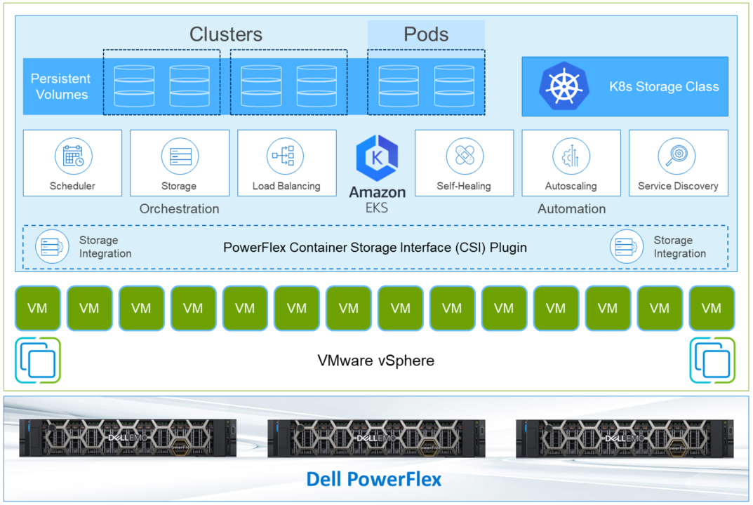
There are two types of templates used for the workloads: a Bottlerocket template and an Ubuntu image. The Bottlerocket template is a customized image from Amazon that is specific to Amazon EKS Anywhere. The Ubuntu template was used for our validation.
Note: Bottlerocket is a Linux-based open-source operating system that is purpose-built by Amazon. It focuses on security and maintainability, and provides a reliable, consistent, and safe platform for container-based workloads. Amazon EKS managed node groups with Bottlerocket support enable you to leverage the simplicity of managed node provisioning and lifecycle management features, while using the latest best practices for running containers in production. You can run your Kubernetes workloads on Bottlerocket nodes and benefit from enhanced security, higher cluster utilization, and less operational overhead. https://aws.amazon.com/blogs/containers/amazon-eks-adds-native-support-for-bottlerocket-in-managed-node-groups/
After the Amazon EKS admin VM is deployed, a command is issued on the Amazon EKS admin VM. This deploys the workload clusters and creates associated CRD instances on the workload cluster. This illustrates the ease of container deployment with Amazon EKS Anywhere. A single instance was prepped, then with some built-in scripting and commands, the system can direct the complex deployment. This greatly simplifies the process when compared to a traditional Kubernetes deployment.
At this point, the deployment can be tested. Amazon provides a test workload that can be used to validate the environment. You can find the details on testing on the Amazon EKS Anywhere documentation site.
The design that was validated was more versatile than a typical Amazon EKS Anywhere deployment. Instead of using the standard VMware CNS-CSI storage provider, this PowerFlex validation uses the Dell PowerFlex CSI plugin. This makes it possible to take direct advantage of PowerFlex’s storage capabilities. With the CSI plugin, it is possible to extend volumes through Amazon EKS, as well as snapshot and restore volumes.
This allows IT departments to move toward developer-oriented processes. Developers can work with storage natively. There are no additional tools to learn and no need to perform operations outside the development environment. This can be a time savings benefit to developer-oriented IT departments.
Beyond storage control in Amazon EKS Anywhere, the results of these operations can be viewed in the PowerFlex management interface. This provides an end-to-end view of the environment and allows traditional IT administrators to use familiar tools to manage and monitor their environment. This makes it easy for the entire IT organization’s journey to move towards a more developer centric environment.
By leveraging Amazon EKS Anywhere on PowerFlex, organizations get on-premises Kubernetes operational tooling that’s consistent with Amazon EKS. Organizations are able to leverage the Amazon EKS console to view all of their Kubernetes clusters (including Amazon EKS Anywhere clusters) running anywhere, through the Amazon EKS Connector. This brings together both the data center and cloud, simplifying the management of both.
In this journey, we have seen that Amazon EKS Anywhere has been validated on Dell PowerFlex, shown how they work together, and enable expanded storage capabilities for developers inside of Amazon EKS Anywhere. It also allows you to use familiar tools in managing the environment. To find out more about Amazon EKS anywhere on PowerFlex, talk with your Dell representative.
Author: Tony Foster, Sr. Technical Marketing Engineer
Twitter: @wonder_nerd LinkedIn

Phenomenal Power: Automating Dell EMC vSAN Ready Nodes
Tue, 16 Nov 2021 21:07:04 -0000
|Read Time: 0 minutes
Dell EMC vSAN Ready Nodes have Identity Modules that act at the lowest level of a node and imbues a host with special features and characteristics. In this blog, we explore how to use the attributes of the Identity Module to automate tasks in a vSphere environment.
Let’s start out by identifying all the Dell EMC vSAN Ready Nodes in our environment and displaying some information about them, such as the BIOS version of each host and vSphere version. After we learn about the hosts in our environment, we will discover what VMs are running on those hosts. We’ll do all of this through VMware’s PowerCLI, which is a plug-in for Microsoft PowerShell.
Note: We could also easily do this using other tools for vSphere such as Python (with pyVmomi), Ansible, and many others.
The environment we are using is a small environment using three Dell EMC vSAN Ready Nodes R740 with identity modules. All three nodes are running ESXi 7.0 U2 (vSAN 7.0 Update 2). VMware vSAN is using an all flash configuration. The code we are discussing in this post should work across current Dell EMC vSAN Ready Nodes and current vSphere releases.
The code displayed below may seem trivial, but you can use it as a base to create powerful scripts! This unlocks many automation capabilities for organizations. It also moves them further along in their autonomous operations journey. If you’re not familiar with autonomous operations, read this white paper to see where your organization is with automation. After reading it, also consider where you want your organization to go.
We’re not going to cover many of the things necessary to build and run these scripts, like connecting to a vSphere environment. There are many great blogs that cover these details, and we want to focus on the code for Dell EMC vSAN Ready Nodes.
In this first code block, we start by finding all the Dell EMC vSAN Ready Nodes in our environment. We use a ForEach-Object loop to do this.
Get-VMhost -State "connected" | ForEach-Object {
     if ($_.ExtensionData.hardware.systemInfo.model.contains("vSAN Ready Node")){
         echo "================================================="
         echo "System Details"
         echo "Model: " $_.ExtensionData.hardware.systemInfo.model
         echo "Service Tag: " $_.ExtensionData.hardware.systemInfo.serialNumber
         echo "BIOS version: " $_.ExtensionData.hardware.biosInfo.biosVersion
         echo "ESXi build: " $_.ExtensionData.config.product.build
     }
}
This code snippet assumes we have connected to a vSphere environment with the Connect-VIServer command. It then creates a view of all the hosts in the environment using the Get-VMhost command, the results of which are passed to the ForEach-Object loop using the | (pipe) symbol. We then loop through this view of hosts using a ForEach-Object command and look at the hardware.systemInfo.model property of each host. The object of focus, one of the discovered hosts, is represented by the $_ variable, and to access the properties of the host object, we use the ExtensionData property. We check each host with a conditional method, .contains(), added on to the end of the property we want to check. Using the .contains method, we check if the hardware.systemInfo.model contains “vSAN Ready Node”. This string is a property that is unique to Dell EMC vSAN Ready Nodes and the Identity Module. It’s set at the factory when the Identity Module is installed.
If the system is a Dell EMC vSAN Ready Node with an Identity Module, we then display information from the hardware.systemInfo and the hardware.biosInfo, specifically the system’s BIOS version. We also collect the vSphere build of the host using the config.product property of the host.
As we loop through each host, we only display these details for the Dell EMC vSAN Ready Nodes in the environment that have Identity Modules. This results in output similar to the following:
The remainder of the nodes are excluded from the output shown here:
PS C:> .\IDM_Script.ps1
=================================================
System Details
Model:
PowerEdge R740 vSAN Ready Node
Service Tag:
[redacted]
BIOS version:
 2.1.12
ESXi build:
18538813
This provides relevant information that we can use to create automated reports about our environment. You can also use the script as the basis for larger automation projects. For example, when a new Dell EMC vSAN Ready node is added to an environment, a script could detect that addition, perform a set of tasks for new Dell EMC vSAN Ready Nodes, and notify the IT team when they are complete. These sample scripts can be used as a spark for your own ideas.
This next script uses the same for loop from before to find the hosts that are Dell EMC vSAN Ready Nodes and now looks to see what VMs are running on the host. From this example, we can see how the Identity Module is integral in automating the virtual environment from the hosts to the virtual machines.
Get-VMhost -state "connected" | ForEach-Object {
    if ($_.ExtensionData.hardware.systemInfo.model.contains("vSAN Ready Node")){
        echo "================================================="

        echo "System Details"
        echo "Model: " $_.ExtensionData.hardware.systemInfo.model
        echo "Service Tag: " $_.ExtensionData.hardware.systemInfo.serialNumber
        echo "BIOS version: " $_.ExtensionData.hardware.biosInfo.biosVersion
        echo "ESXi build: " $_.ExtensionData.config.product.build
        echo "+++++++++++++++++++++++++++++++++++++++++++++++++"
        echo "$_ list of VMs:"
        Get-VM -Location $_ | ForEach-Object{
            echo $_.ExtensionData.name
        }
    }
}
This new code snippet, shown in bold, builds on the previous example by looping through our hosts looking for the “vSAN Ready Node” as before. When it finds a matching host, it creates a new view using the Get-VM command, consisting of the virtual machines for that host. The host is specified using the -Location parameter, to which is passed the current host represented by the $_. We then use another ForEach-Object loop to display a list of VMs on the host.
This gives our code context. If an action is carried out, we can now define the scope of that action, not just on the host but on the workloads it’s running. We can start to build code with intelligence — extracting a greater value from the system, which in turn provides the opportunity to drive greater value for the organization.
As I said earlier, this is just the starting point of what is possible when building PowerCLI scripts for Dell EMC vSAN Ready Nodes with Identity Modules! Other automation platforms, like Ansible, can also take advantage of the identity module features. We only covered the basics, but there are enormous possibilities beyond discovery operations. The nuggets of knowledge in this blog unlock numerous opportunities for you to build automations that empower your data center.
For more information see Dell EMC vSAN Ready Nodes overview and the Dell EMC VSAN Ready Nodes blog site.
Author Information
Tony Foster

Dell EMC vSAN Ready Nodes: Taking VDI and AI Beyond “Good Enough”
Mon, 18 Oct 2021 13:06:37 -0000
|Read Time: 0 minutes
Some people have speculated that 2020 was “the year of VDI” while others say that it will never be the “year of VDI.” However, there is one certainty. In 2020 and part of 2021, organizations worldwide consumed a large amount of virtual desktop infrastructure (VDI). Some of these deployments went extremely well while other deployments were just “good enough.”
If you are a VDI enthusiast like me, there was much to learn from all that happened over the last 24 months. An interesting observation is that test VDI environments turned into production environments overnight. Also, people discovered that the capacity of clouds is not limitless. My favorite observation is the discovery by many IT professionals that GPUs can change the VDI experience from “good enough” to enjoyable, especially when coupled with an outstanding environment powered by Dell Technologies with VMware vSphere and VMware Horizon.
In this blog, I will tell you about how exceptional VDI (and AI/ML) is when paired with powerful technology.
This blog does not address cloud workloads as it is a substantial topic. It would be difficult for me to provide the proper level of attention in this blog, so I will address only on premises deployments.
Many end users adopt hyperconverged infrastructure (HCI) in their data centers because it is easy to consume. One of the most popular HCIs is Dell EMC VxRail Hyperconverged Infrastructure. You can purchase nodes to match your needs. These needs range from the traditional data center workloads, to Tanzu clusters, to VDI with GPUs, and to AI. VxRail enables you to deliver whatever your end users need. Your end users might be developers working from home on a containers-based AI project and they need a development environment, VxRail can provide it with relative ease.
Some IT teams might want an HCI experience that is more customer managed but they still want a system that is straightforward to deploy, validate, and is easy to maintain. This scenario is where Dell EMC vSAN Ready Nodes come into play.
Dell EMC vSAN Ready Nodes provide comprehensive, flexible, and efficient solutions optimized for your workforce’s business goals with a large choice of options (more than 250 as of the September 29, 2021 vSAN Compatibility Guide) from tower to rack mount to blades. A surprising option is that you can purchase Dell EMC vSAN Ready Nodes with GPUs, making them a great platform for VDI and virtualized AI/ML workloads.
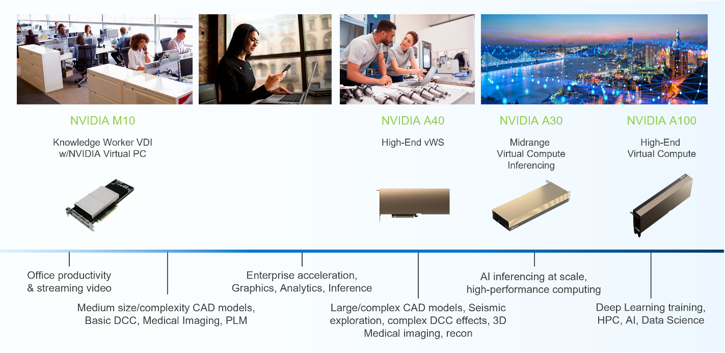
Dell EMC vSAN Ready Nodes supports many NVIDIA GPUs used for VDI and AI workloads, notably the NVIDIA M10 and A40 GPUs for VDI workloads and the NVIDIA A30 and A100 GPUs for AI workloads. There are other available GPUs depending on workload requirements, however, this blog focuses on the more common use cases.
For some time, the NVIDIA M10 GPU has been the GPU of choice for VDI-based knowledge workers who typically use applications such as Microsoft PowerPoint and YouTube. The M10 GPU provides a high density of users per card and can support multiple virtual GPU (vGPU) profiles per card. The multiple profiles result from having four GPU chips per PCI board. Each chip can run a unique vGPU profile, which means that you can have four vGPU profiles. That is, there are twice as many profiles than are provided by other NVIDIA GPUs. This scenario is well suited for organizations with a larger set of desktop profiles.
Combining this profile capacity with Dell EMC vSAN Ready Nodes, organizations can deliver various desktop options yet be based on a standardized platform. Organizations can let end users choose the system that suites them best and can optimize IT resources by aligning them to an end user’s needs.
Typically, power users need or want more graphics capabilities than knowledge workers. For example, power users working in CAD applications need larger vGPU profiles and other capabilities like NVIDIA’s Ray Tracing technology to render drawings. These power users’ VDI instances tend to be more suited to the NVIDIA A40 GPU and associated vGPU profiles. It allows power users who do more than create Microsoft PowerPoint presentations and watch YouTube videos to have the desktop experience they need to work effectively.
The ideal Dell EMC vSAN Ready Nodes platform for the A40 GPU is based on the Dell EMC PowerEdge R750 server. The PowerEdge R750 server provides the power and capacity for demanding workloads like healthcare imaging and natural resource exploration. These workloads also tend to take full advantage of other features built into NVIDIA GPUs like CUDA. CUDA is a parallel computing platform and programming model that uses GPUs. It is used in many high-end applications. Typically, CUDA is not used with traditional graphics workloads.
In this scenario, we start to see the blend between graphics and AI/ML workloads. Some VDI users not only render complex graphics sets, but also use the GPU for other computational outcomes, much like AI and ML do.
I really like that I can run AI/ML workloads in a virtual environment. It does not matter if you are an IT administrator or an AI/ML administrator. You can run AI and ML workloads in a virtual environment.
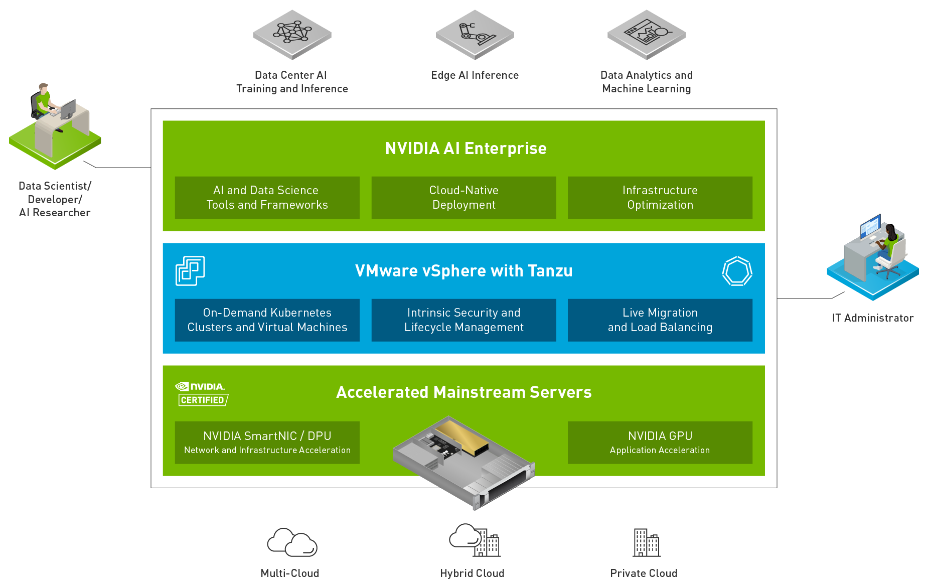
Many organizations have realized that the same benefits virtualization has brought to IT can also be realized in the AI/ML space. There are additional advantages, but those are best kept for another time.
For some organizations, IT is now responsible for AI/ML environments, whether delivering test/dev environments for programmers or delivering a complete AI training environment. For other IT groups, this responsibility falls to highly paid data scientists. And for some IT groups, the responsibility is a mix.
In this scenario, virtualization shines. IT administrators can do what they do best: deliver a powerful Dell EMC vSAN Ready Node infrastructure. Then, data scientists can spend their time building systems in a virtual environment consuming IT resources instead of racking and cabling a server.
Dell EMC vSAN Ready nodes are great for many AI/ML applications. They are easy to consume as a single unit of infrastructure. Both the NVIDIA A30 GPU and the A100 GPU are available so that organizations can quickly and easily assemble the ideal architecture for AI/ML workloads.
This ease of consumption is important for both IT and data scientists. It is unacceptable when IT consumers like data scientists must wait for the infrastructure they need to do their job. Time is money. Data scientists need environments quickly, which Dell EMC vSAN Ready Nodes can help provide. Dell EMC vSAN Ready Nodes deploy 130 percent faster with Dell EMC OpenManage Integration for VMware vCenter (OMIVV) (Based on Dell EMC internal competitive testing of PowerEdge and OMIVV compared to Cisco UCS manual operating system deployment.)
This speed extends beyond day 0 (deployment) to day 1+ operations. When using the vLCM and OMIVV, complete hypervisor and firmware updates to an eight-node PowerEdge cluster took under four minutes compared to a manual process, which took3.5 hours.(Principle Technologies report commissioned by Dell Technologies, New VMware vSphere 7.0 features reduced the time and complexity of routine update and hardware compliance tasks, July 2020.)
Dell EMC vSAN Ready Nodes ensures that you do not have to be an expert in hardware compatibility. With over 250 Dell EMC vSAN Ready Nodes available (as of the September 29, 2021 vSAN Compatibility Guide), you do not need to guess which drives will work or if a network adapter is compatible. You can then focus more on data and the results and less on building infrastructure.
These time-to-value considerations, especially for AI/ML workloads, are important. Being able to deliver workloads such as AI/ML or VDI quickly can have a significant impact on organizations, as has been evident in many organizations over the last two years. It has been amazing to see how fast organizations have adopted or expanded their VDI environments to accommodate everyone from knowledge workers to high-end power users wherever they need to consume IT resources.
Beyond “just expanding VDI” to more users, organizations have discovered that GPUs can improve the end-user experience and, in some cases, not only help but were required. For many, the NVIDIA M10 GPU helped users gain the wanted remote experience and move beyond “good enough.” For others who needed a more graphics-rich experience, the NVIDIA A40 GPU continues to be an ideal choice.
When GPUs are brought together as part of a Dell EMC vSAN Ready Node, organizations have the opportunity to deliver an expanded VDI and AI/ML experience to their users. To find out more about Dell EMC vSAN Ready Nodes, see Dell EMC vSAN Ready Nodes.
Author: Tony Foster Twitter: @wonder_nerd LinkedIn: https://linkedin.com/in/wondernerd