


Introducing NVMe over TCP (NVMe/TCP) in PowerFlex 4.0

Anyone who has used or managed PowerFlex knows that an environment is built from three lightweight software components: the MDM, the SDS, and the SDC. To deploy a PowerFlex environment, the typical steps are:
- Deploy an MDM management cluster
- Create a cluster of storage servers by installing and configuring the SDS software component
- Add Protection Domains and Storage Pools
- Install the SDC onto client systems
- Provision volumes and away you go!!*
*No requirement for multipath software, this is all handled by the SDC/SDS
There have been additions to this over the years, such as an SDR component for replication and the configuration of NVDIMM devices to create finegranularity storage pools that provide compression. Also added are PowerFlex rack and appliance environments. This is all automated with PowerFlex Manager. Fundamentally, the process involves the basic steps outlined above.
So, the question is why would we want to change anything from an elegant solution that is so simple?
This is due to where the SDC component ‘lives’ in the operating system or hypervisor hosting the application layer. Referring to the diagram below, it shows that the SDC must be installed in the kernel of the operating system or hypervisor, meaning that the SDC and the kernel must be compatible. Also the SDC component must be installed and maintained, it does not just ‘exist’.
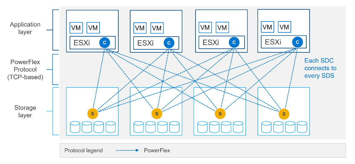
In most cases, this is fine and there are no issues whatsoever. The PowerFlex development team keeps the SDC current with all the major operating system versions and customers are happy to update the SDC within their environment when new versions become available.
There are, however, certain cases where manual deployment and management of the SDC causes significant overhead. There are also some edge use cases where there is no SDC available for specific operating systems. This is why the PowerFlex team has investigated alternatives.
In recent years, the use of Non-Volatile Memory Express (NVMe) has become pervasive within the storage industry. It is seen as the natural replacement to SCSI, due to its simplified command structure and its ability to provide multiple queues to devices, aligning perfectly with modern multi-core processors to provide very high performance.
NVMe appeared initially as a connection directly to disks within a server over a PCIe connection, progressing to being used over a variety of fabric interconnects.
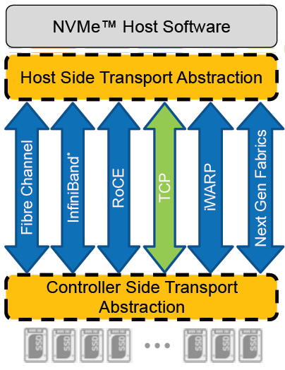
Added to this is the widespread support for NVMe/TCP across numerous operating system and hypervisor vendors. Most include support natively in their kernels.
There have been several announcements by Dell Technologies over the past months highlighting NVMe/TCP as an alternative interconnect to iSCSI across several of the storage platforms within the portfolio. It is therefore a natural progression for PowerFlex to also provide support for NVMe/TCP, particularly because it already uses a TCP-based interconnect.
PowerFlex implements support for NVMe/TCP with the introduction of a new component installed in the storage layer called the SDT.
The SDT is installed at the storage layer. The NVMe initiator in the operating system or hypervisor communicates with the SDT, which then communicates with the SDS. The NVMe initiator is part of the kernel of the operating system or hypervisor.
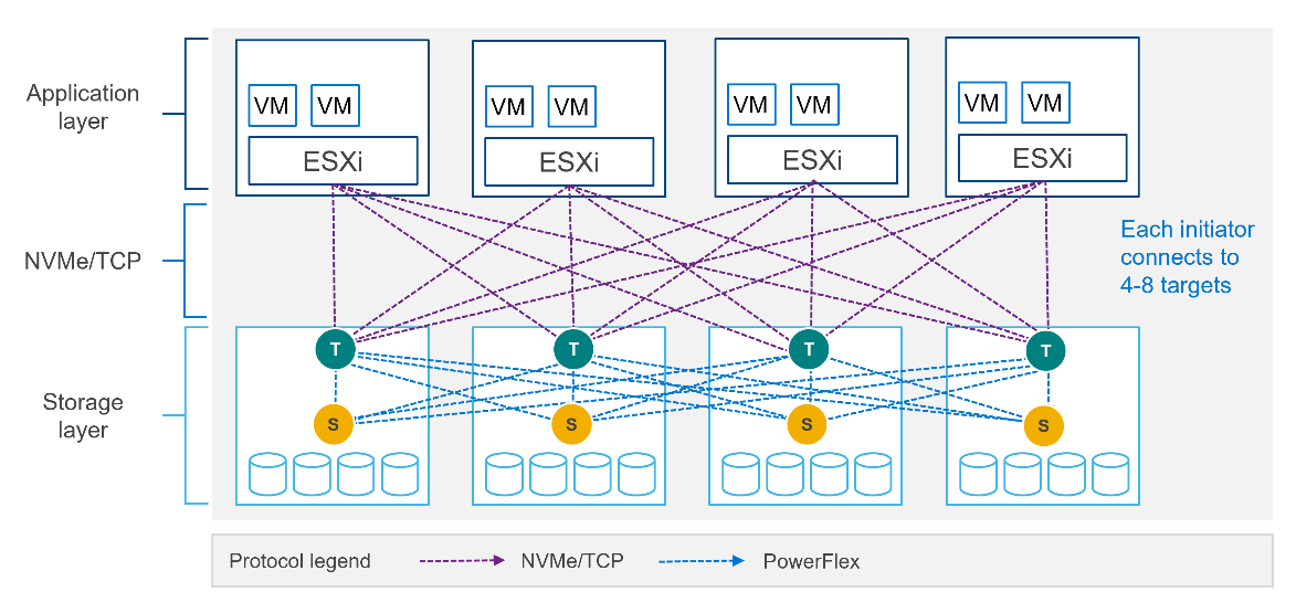
Of course, because PowerFlex is so ‘flexible,’ both connection methods (SDC and NVMe/TCP) are supported at the same time. The only limitation is that a volume can only be presented using one protocol or the other.
For the initial PowerFlex 4.0 release, the VMware ESXi hypervisor is supported. This support starts with ESXi 7.0 U3f. Support for Linux TCP initiators is currently in “tech preview” as the initiators continue to grow and mature, allowing for all failure cases to be accounted for.
NVMe/TCP is a very powerful solution for the workloads that take advantage of it. If you are interested in discovering more about how PowerFlex can enhance your datacenter, reach out to your Dell representative.
Authors:
Kevin M Jones, PowerFlex Engineering Technologist.
Tony Foster, Senior Principal Technical Marketing Engineer.
Twitter: @wonder_nerd
LinkedIn
Related Blog Posts

Can I do that AI thing on Dell PowerFlex?
Thu, 20 Jul 2023 21:08:09 -0000
|Read Time: 0 minutes
The simple answer is Yes, you can do that AI thing with Dell PowerFlex. For those who might have been busy with other things, AI stands for Artificial Intelligence and is based on trained models that allow a computer to “think” in ways machines haven’t been able to do in the past. These trained models (neural networks) are essentially a long set of IF statements (layers) stacked on one another, and each IF has a ‘weight’. Once something has worked through a neural network, the weights provide a probability about the object. So, the AI system can be 95% sure that it’s looking at a bowl of soup or a major sporting event. That, at least, is my overly simplified description of how AI works. The term carries a lot of baggage as it’s been around for more than 70 years, and the definition has changed from time to time. (See The History of Artificial Intelligence.)
Most recently, AI has been made famous by large language models (LLMs) for conversational AI applications like ChatGPT. Though these applications have stoked fears that AI will take over the world and destroy humanity, that has yet to be seen. Computers still can do only what we humans tell them to do, even LLMs, and that means if something goes wrong, we their creators are ultimately to blame. (See ‘Godfather of AI’ leaves Google, warns of tech’s dangers.)
The reality is that most organizations aren’t building world destroying LLMs, they are building systems to ensure that every pizza made in their factory has exactly 12 slices of pepperoni evenly distributed on top of the pizza. Or maybe they are looking at loss prevention, or better traffic light timing, or they just want a better technical support phone menu. All of these are uses for AI and each one is constructed differently (they use different types of neural networks).
We won’t delve into these use cases in this blog because we need to start with the underlying infrastructure that makes all those ideas “AI possibilities.” We are going to start with the infrastructure and what many now consider a basic (by today’s standards) image classifier known as ResNet-50 v1.5. (See ResNet-50: The Basics and a Quick Tutorial.)
That’s also what the PowerFlex Solution Engineering team did in the validated design they recently published. This design details the use of ResNet-50 v1.5 in a VMware vSphere environment using NVIDIA AI Enterprise as part of PowerFlex environment. They started out with the basics of how a virtualized NVIDIA GPU works well in a PowerFlex environment. That’s what we’ll explore in this blog – getting started with AI workloads, and not how you build the next AI supercomputer (though you could do that with PowerFlex as well).
In this validated design, they use the NVIDIA A100 (PCIe) GPU and virtualized it in VMware vSphere as a virtual GPU or vGPU. With the infrastructure in place, they built Linux VMs that will contain the ResNet-50 v1.5 workload and vGPUs. Beyond just working with traditional vGPUs that many may be familiar with, they also worked with NVIDIA’s Multi-Instance GPU (MIG) technology.
NVIDIA’s MIG technology allows administrators to partition a GPU into a maximum of seven GPU instances. Being able to do this provides greater control of GPU resources, ensuring that large and small workloads get the appropriate amount of GPU resources they need without wasting any.
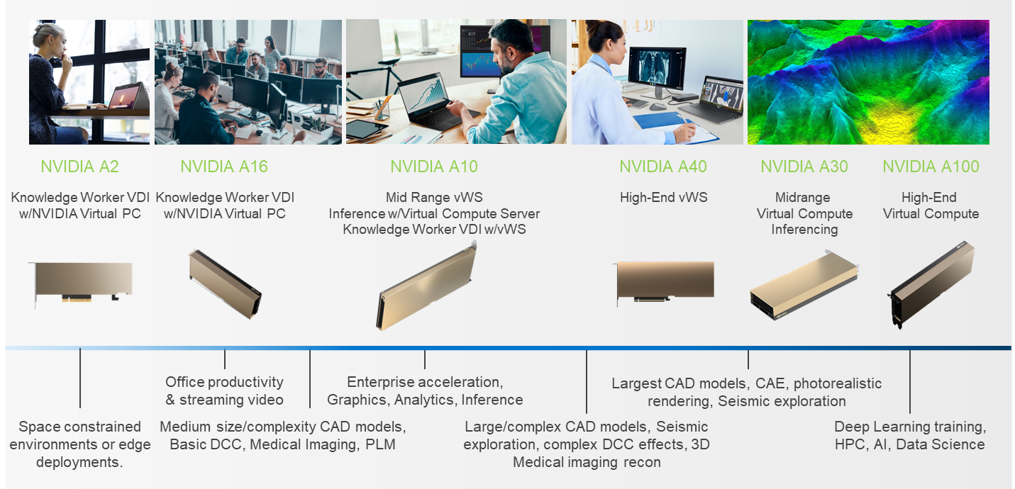
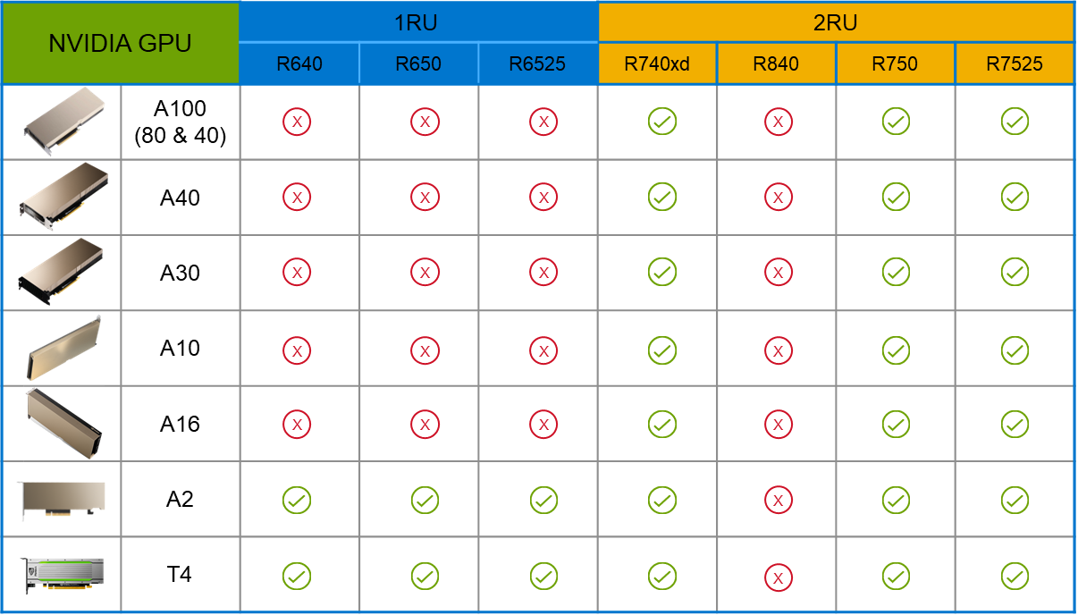
PowerFlex supports a large range of NVIDIA GPUs for workloads, from VDI (Virtual Desktops) to high end virtual compute workloads like AI. You can see this in the following diagram where there are solutions for “space constrained” and “edge” environments, all the way to GPUs used for large inferencing models. In the table below the diagram, you can see which GPUs are supported in each type of PowerFlex node. This provides a tremendous amount of flexibility depending on your workloads.
The validated design describes the steps to configure the architecture and provides detailed links to the NVIDIAand VMware documentation for configuring the vGPUs, and the licensing process for NVIDIA AI Enterprise.
These are key steps when building an AI environment. I know from my experience working with various organizations, and from teaching, that many are not used to working with vGPUs in Linux. This is slowly changing in the industry. If you haven’t spent a lot of time working with vGPUs in Linux, be sure to pay attention to the details provided in the guide. It is important and can make a big difference in your performance.
The following diagram shows the validated design’s logical architecture. At the top of the diagram, you can see four Ubuntu 22.04 Linux VMs with the NVIDIA vGPU driver loaded in them. They are running on PowerFlex hosts with VMware ESXi deployed. Each VM contains one NVIDIA A100 GPU configured for MIG operations. This configuration leverages a two-tier architecture where storage is provided by separate PowerFlex software defined storage (SDS) nodes.
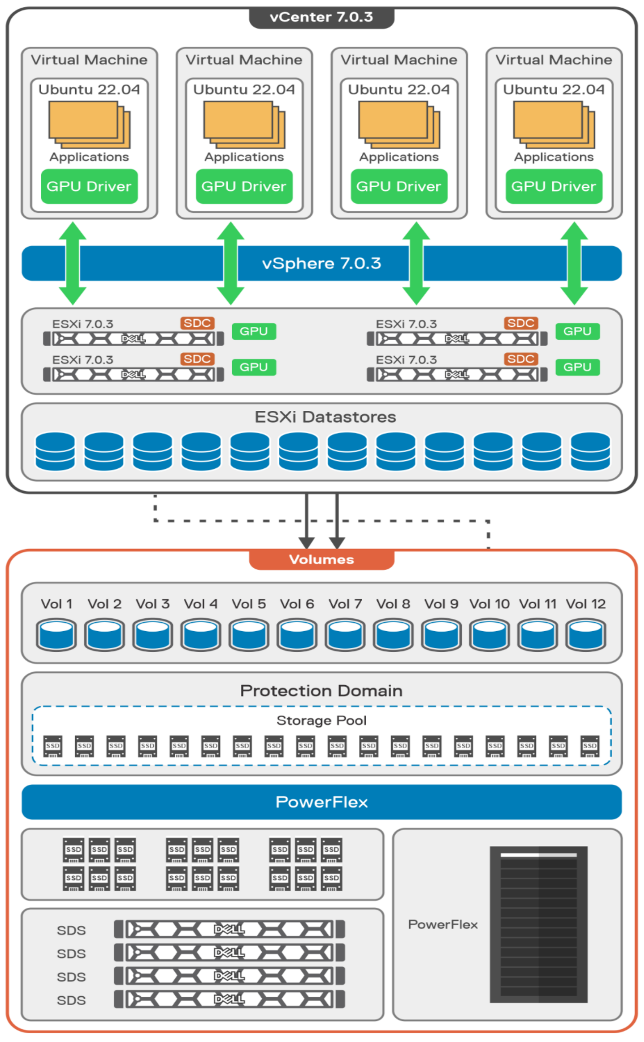
A design like this allows for independent scalability for your workloads. What I mean by this is during the training phase of a model, significant storage may be required for the training data, but once the model clears validation and goes into production, storage requirements may be drastically different. With PowerFlex you have the flexibility to deliver the storage capacity and performance you need at each stage.
This brings us to testing the environment. Again, for this paper, the engineering team validated it using ResNet-50 v1.5 using the ImageNet 1K data set. For this validation they enabled several ResNet-50 v1.5 TensorFlow features. These include Multi-GPU training with Horovod, NVIDIA DALI, and Automatic Mixed Precision (AMP). These help to enable various capabilities in the ResNet-50 v1.5 model that are present in the environment. The paper then describes how to set up and configure ResNet-50 v1.5, the features mentioned above, and details about downloading the ImageNet data.
At this stage they were able to train the ResNet-50 v1.5 deployment. The first iteration of training used the NVIDIA A100-7-40C vGPU profile. They then repeated testing with the A100-4-20C vGPU profile and the A100-3-20C vGPU profile. You might be wondering about the A100-2-10C vGPU profile and the A100-1-5C profile. Although those vGPU profiles are available, they are more suited for inferencing, so they were not tested.
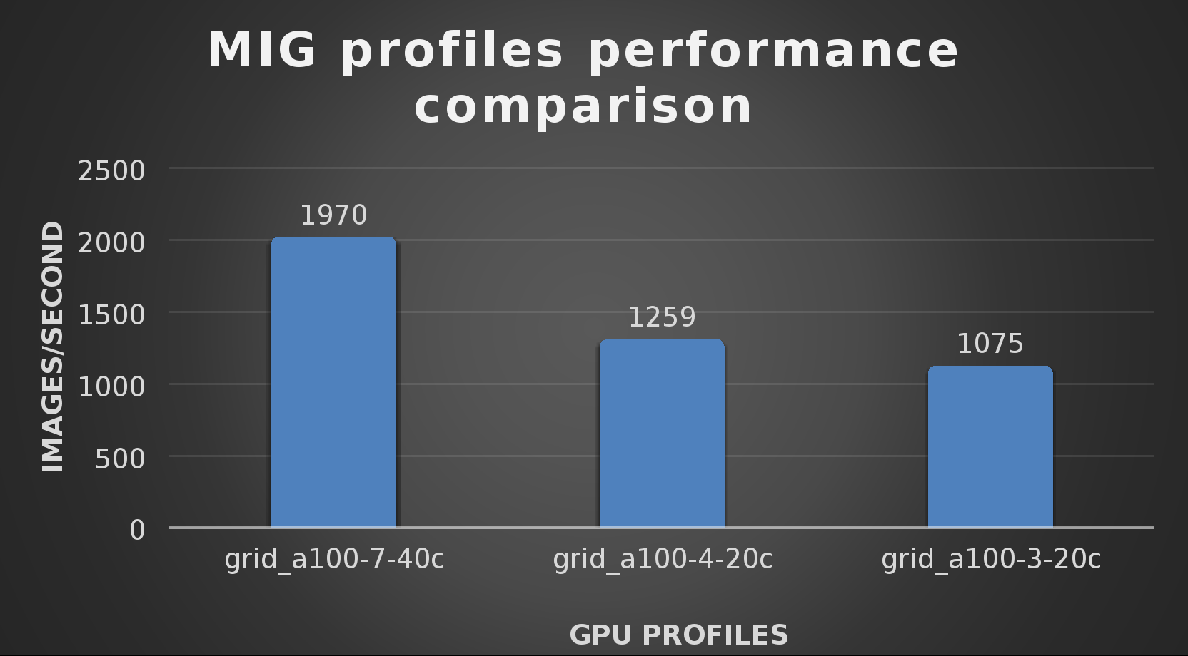
The results from validating the training workloads for each vGPU profile is shown in the following graph. The vGPUs were running near 98% capacity according to nvitop during each test. The CPU utilization was 14% and there was no bottle neck with the storage during the tests.
With the models trained, the guide then looks at how well inference runs on the MIG profiles. The following graph shows inferencing images per second of the various MIG profiles with ResNet-50 v1.5.
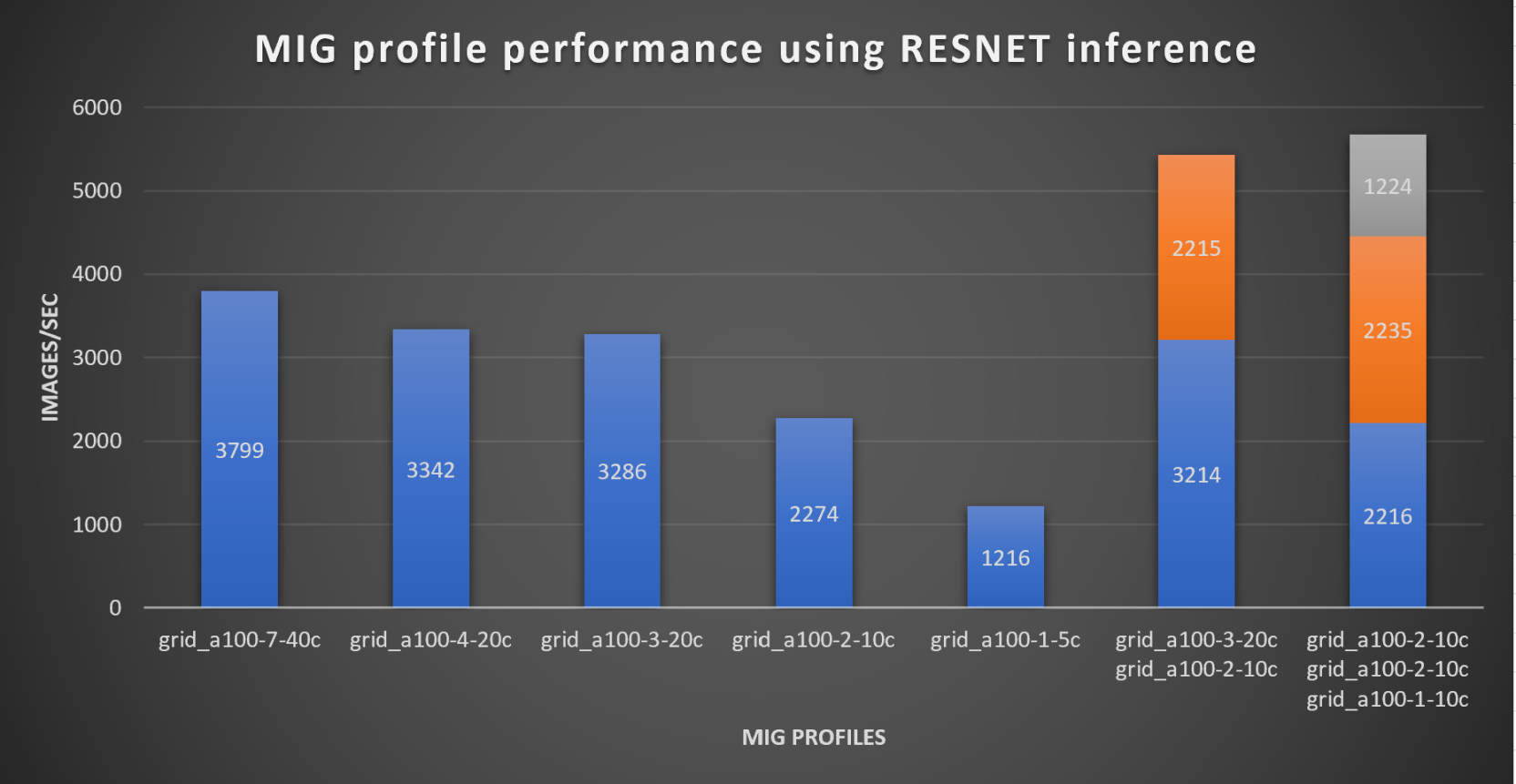
It’s worth noting that the last two columns show the inferencing running across multiple VMs, on the same ESXi host, that are leveraging MIG profiles. This also shows that GPU resources are partitioned with MIG and that resources can be precisely controlled, allowing multiple types of jobs to run on the same GPU without impacting other running jobs.
This opens the opportunity for organizations to align consumption of vGPU resources in virtual environments. Said a different way, it allows IT to provide “show back” of infrastructure usage in the organization. So if a department only needs an inferencing vGPU profile, that’s what they get, no more, no less.
It’s also worth noting that the results from the vGPU utilization were at 88% and CPU utilization was 11% during the inference testing.
These validations show that a Dell PowerFlex environment can support the foundational components of modern-day AI. It also shows the value of NVIDIA’s MIG technology to organizations of all sizes: allowing them to gain operational efficiencies in the data center and enable access to AI.
Which again answers the question of this blog, can I do that AI thing on Dell PowerFlex… Yes you can run that AI thing! If you would like to find out more about how to run your AI thing on PowerFlex, be sure to reach out to your Dell representative.
Resources
- The History of Artificial Intelligence
- ‘Godfather of AI’ leaves Google, warns of tech’s dangers
- ResNet-50: The Basics and a Quick Tutorial
- Dell Validated Design for Virtual GPU with VMware and NVIDIA on PowerFlex
- NVIDIA NGC Catalog ResNet v1.5 for PyTorch
- NVIDIA AI Enterprise
- NVIDIA A100 (PCIe) GPU
- NVIDIA Virtual GPU Software Documentation
- NVIDIA A100-7-40C vGPU profile
- NVIDIA Multi-Instance GPU (MIG)
- NVIDIA Multi-Instance GPU User Guide
- Horovod
- ImageNet
- DALI
- Automatic Mixed Precision (AMP)
- nvitop
Author: Tony Foster
Sr. Principal Technical Marketing Engineer
Twitter: | |
LinkedIn: | |
Personal Blog: | |
Location: | The Land of Oz [-6 GMT] |

An Introduction to the Unified PowerFlex Manager Platform
Tue, 16 Aug 2022 14:56:28 -0000
|Read Time: 0 minutes
We have all heard the well-known quote that “Change is the only constant in life”. Nowhere is this concept more apparent than in the world of IT, where digital transformation has become accepted as a fact of life and standing still is not an option. Anyone - or anything - that stands still in the world of IT faces becoming extinct, or irrelevant, when faced with responding to the ever-changing challenges that businesses must solve to survive and grow in the 21st Century. IT infrastructure has had to evolve to provide the answers needed in today’s business landscape – a world where Dev Ops and automation is driving business agility and productivity, where flexibility is key, and where consolidation and optimization are essential in the face of ever-shrinking budgets.
When dealing with the ever-changing IT landscape, software-defined infrastructure is ideally suited to delivering answers for business change. Indeed, many Dell Technologies customers choose PowerFlex as their software-defined infrastructure solution of choice because as a product, it has changed and evolved as much as customers themselves have had to change and evolve.
However, there are times when evolution itself is not enough to bring about inevitable changes that must occur - sometimes there must be a revolution! When it comes to IT infrastructure, managers are often given the “coin toss” of only being able to pick from either evolution or revolution. Faced with such a decision, managers often choose evolution over revolution – a simpler, more palatable path.
This was the dilemma that PowerFlex developers faced – continue with various separate management planes or unify them. Our developers were already planning to introduce several new features in PowerFlex 4.0, including PowerFlex File Services and NVMe/TCP connectivity. Adding new features to existing products generally means having to change the existing management tools and user interfaces to integrate the new functionality into the existing toolset. PowerFlex has a broad product portfolio and a broad set of management tools to match, as shown in the following figure. The uptake of customers using PowerFlex Manager was proof-positive that customers liked to use automation tools to simplify their infrastructure deployments and de-risk life-cycle management (LCM) tasks.
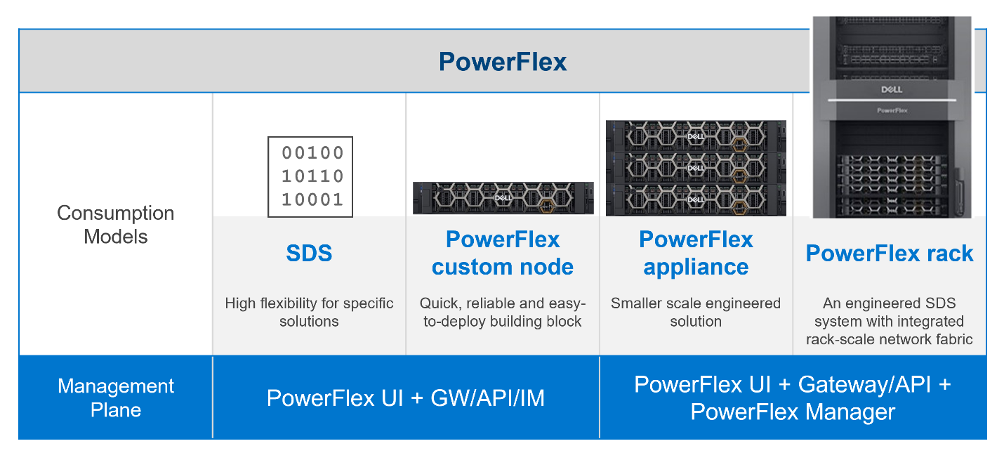
Figure 1: PowerFlex management planes, before PowerFlex 4.0
In addition to the multiple demands they had to contend with, the PowerFlex team was aware that new, as-yet unthought of demands would inevitably come to the surface in the future, as the onward progression of IT transformation continues.
Aiming to enhance the hybrid datacenter infrastructure that our customers are gravitating towards, simply evolving the existing management planes was not going to be sufficient. The time had come for revolution instead of evolution for the world of PowerFlex management.
The answer is simple to state, but not easy to achieve – design a new Management & Orchestration platform that reduces complexity for our customers. The goal was to simplify things by having a single management plane that is suitable for all customers, regardless of their consumption model. Revolution indeed!
Given a blank drawing board, the PowerFlex Team drew up a list of requirements needed for the new PowerFlex Management stack. The following is a simplified list:
- Unified RBAC and User Management. Implement single sign-on for authentication and authorization, ensuring that only a single set of roles is needed throughout PowerFlex.
- Have a single, unified web UI – but make it extensible, so that as new functionality becomes available, it can easily be added to the UI without breaking it. The addition of “PowerFlex File Services” with PowerFlex 4.0 is proof that this approach works!
- Create a single REST endpoint for all APIs, to ensure that both the legacy and the modern endpoints are accessible through a standardized PowerAPI.
- Ensure that the management stack is highly available, self-healing, and resilient.
- Centralize all events from all PowerFlex components – the SDS itself, switches, nodes, and resources, so that it simplifies the generation of alerts and call home operations.
Faced with this wish list, the team decided to build a new “unified” PowerFlex Manager to satisfy the “one management pane” requirement. But how to deliver a UI that is flexible enough to deal with serving different applications from a single web UI? How can this support a highly available and extensible management platform? It became clear to all that a new M&O stack was needed to achieve these aims and that the answer was to leverage the use of microservices, running as part of a larger, containerized platform.
Around the same time, the Dell ISG Development Team had been working internally on a new shared services platform. It was now ready for primetime. This Dell-developed Kubernetes distribution provides internal shared services that are required by nearly any IT infrastructure: logging services, database-as-a-service, certificate management, identity management, secrets management. It also manages Docker and Helm registries.
Using this new platform as a base, the PowerFlex Team then deployed additional microservices on top of it to micro-manage services specific to PowerFlex. Different micro-frontends can be called upon, depending on the operational context. While the overall PowerFlex Manager GUI application can be run as one “generic” UI, it can call out to different micro-frontends when required. This means that implementing and using microservices simplifies the transfer of previous element managers into the unified PowerFlex Manager world. For example, the traditional PowerFlex Block UI (the PowerFlex Presentation Server UI from PowerFlex 3.6) is now treated as one microservice, while the PowerFlex Manager Lifecycle Manager is now handled by several microservices all working in tandem. Plus, it becomes simple to add a new micro-frontend to handle the “PowerFlex File” functionality that has been released with PowerFlex 4.0 into the GUI as well. Because each GUI section now has its own micro-frontend, the UI now meets the “flexible and extensible” requirement.
This flexibility gives our existing PowerFlex customers assurance as they move from version 3.6 to 4.0. And equally important, it means there is now a single unified manager that can cover all consumption models, as shown in the following figure:
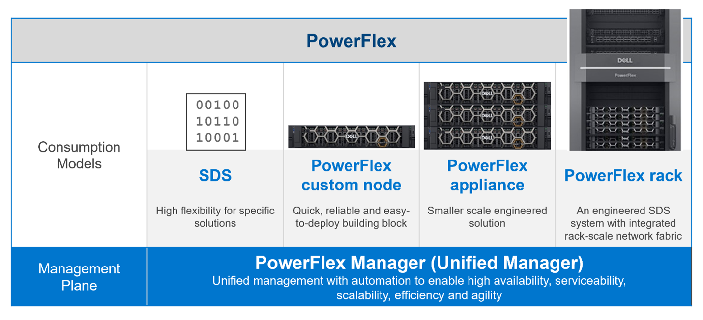
Figure 2. The unified PowerFlex Management Plane with PowerFlex 4.0
Finally, what does the new unified PowerFlex Manager look like? Existing PowerFlex users will be pleased to see that the new unified PowerFlex Manager still has the same “look and feel” that PowerFlex Manager 3.x had. We hope this will make it easier for operations staff when they decide to upgrade from PowerFlex 3.x to PowerFlex 4.0. The following figures show the Block and File Services tabs respectively:
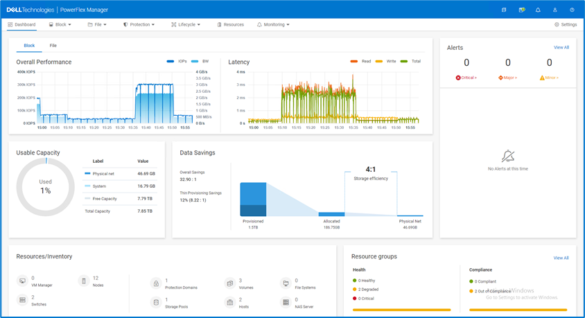
Figure 3. The unified PowerFlex Manager 4.0 Dashboard

Figure 4. The unified PowerFlex Manager 4.0 – Resources
While we cannot stop progress, we can always excel when faced with an ever-changing landscape. Customers already choose PowerFlex when they want to deploy highly performant, scalable, resilient, and flexible software-defined infrastructures. They can now also choose to move to PowerFlex 4.0, safe in the knowledge that they have also future-proofed the management of their infrastructure. While they may not know what changes are in store, the unified PowerFlex Manager Platform will help ensure that those future changes, whatever they are, can be handled easily when deployed on top of PowerFlex.
The enhancements made to PowerFlex provide many possibilities for modern datacenters and their administrators, especially when faced with the constant digital transformation seen in IT today. This is seen in how the various PowerFlex management consoles have been unified to allow continued change and growth to meet organizations’ needs. Yet, there is also continuity with previous versions of the UI, ensuring an easy transition for users when they have migrated to 4.0. If you are interested in finding out more about PowerFlex and all it has to offer your organization, reach out to your Dell representative.
Authors: Simon Stevens, PowerFlex Engineering Technologist, EMEA.
Tony Foster, Senior Principal Technical Marketing Engineer.
Twitter: @wonder_nerd
LinkedIn