Blogs
The latest news about PowerFlex releases and updates

A Simple Poster at NVIDIA GTC – Running NVIDIA Riva on Red Hat OpenShift with Dell PowerFlex


Fri, 15 Mar 2024 21:45:09 -0000
|Read Time: 0 minutes
A few months back, Dell and NVIDIA released a validated design for running NVIDIA Riva on Red Hat OpenShift with Dell PowerFlex. A simple poster—nothing more, nothing less—yet it can unlock much more for your organization. This design shows the power of NVIDIA Riva and Dell PowerFlex to handle audio processing workloads.
What’s more, it will be showcased as part of the poster gallery at NVIDIA GTC this week in San Jose California. If you are at GTC, we strongly encourage you to join us during the Poster Reception from 4:00 to 6:00 PM. If you are unable to join us, you can view the poster online from the GTC website.
For those familiar with ASR, TTS, and NMT applications, you might be curious as to how we can synthesize these concepts into a simple poster. Read on to learn more.
NVIDIA Riva
For those not familiar with NVIDIA Riva, let’s start there.
NVIDIA Riva is an AI software development kit (SDK) for building conversational AI pipelines, enabling organizations to program AI into their speech and audio systems. It can be used as a smart assistant or even a note taker at your next meeting. Super cool, right?
Taking that up a notch, NVIDIA Riva lets you build fully customizable, real-time conversational AI pipelines, which is a fancy way of saying it allows you to process speech in a bunch of different ways including automatic speech recognition (ASR), text-to-speech (TTS), and neural machine translation (NMT) applications:
- Automatic speech recognition (ASR) – this is essentially dictation. Provide AI with a recording and get a transcript—a near perfect note keeper for your next meeting.
- Text-to-speech (TTS) – a computer reads what you type. In the past, this was often in a monotone voice. It’s been around for more than a couple of decades and has evolved rapidly with more fluid voices and emotion.
- Neural machine translation (NMT) – this is the translation of spoken language in near real-time to a different language. It is a fantastic tool for improving communication, which can go a long way in helping organizations extend business.
Each application is powerful in its own right, so think about what’s possible when we bring ASR, TTS, and NMT together, especially with an AI-backed system. Imagine having a technical support system that could triage support calls, sounded like you were talking to an actual support engineer, and could provide that support in multiple languages. In a word: ground-breaking.
NVIDIA Riva allows organizations to become more efficient in handling speech-based communications. When organizations become more efficient in one area, they can improve in other areas. This is why NVIDIA Riva is part of the NVIDIA AI Enterprise software platform, focusing on streamlining the development and deployment of production AI.
I make it all sound simple, however those creating large language models (LLMs) around multilingual speech and translation software know it’s not so. That’s why NVIDIA developed the Riva SDK.
The operating platform also plays a massive role in what can be done with workloads. Red Hat OpenShift enables AI speech recognition and inference with its robust container orchestration, microservices architecture, and strong security features. This allows workloads to scale to meet the needs of an organization. As the success of a project grows, so too must the project.
Why is Storage Important
You might be wondering how storage fits into all of this. That’s a great question. You’ll need high performance storage for NVIDIA Riva. After all, it’s designed to process and/or generate audio files and being able to do that in near real-time requires a highly performant, enterprise-grade storage system like Dell PowerFlex.
Additionally, AI workloads are becoming mainstream applications in the data center and should be able to run side by side with other mission critical workloads utilizing the same storage. I wrote about this in my Dell PowerFlex – For Business-Critical Workloads and AI blog.
At this point you might be curious how well NVIDIA Riva runs on Dell PowerFlex. That is what a majority of the poster is about.
ASR and TTS Performance
The Dell PowerFlex Solutions Engineering team did extensive testing using the LibriSpeech dev-clean dataset available from Open SLR. With this data set, they performed automatic speech recognition (ASR) testing using NVIDIA Riva. For each test, the stream was increased from 1 to 64, 128, 256, 384, and finally 512, as shown in the following graph.
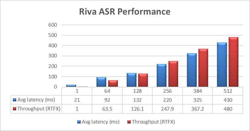 Figure 1. NVIDIA Riva ASR Performance
The objective of these tests is to have the lowest latency with the highest throughput. Throughput is measured in RTFX, or the duration of audio transcribed divided by computation time. During these tests, the GPU utilization was approximately 48% without any PowerFlex storage bottlenecks. These results are comparable to NVIDIA’s own findings in in the NVIDIA Riva User Guide.
The Dell PowerFlex Solutions Engineering team went beyond just looking at how fast NVIDIA Riva could transcribe text, also exploring the speed at which it could convert text to speech (TTS). They validated this as well. Starting with a single stream, for each run the stream is changed to 4, 6, 8, and 10, as shown in the following graph.
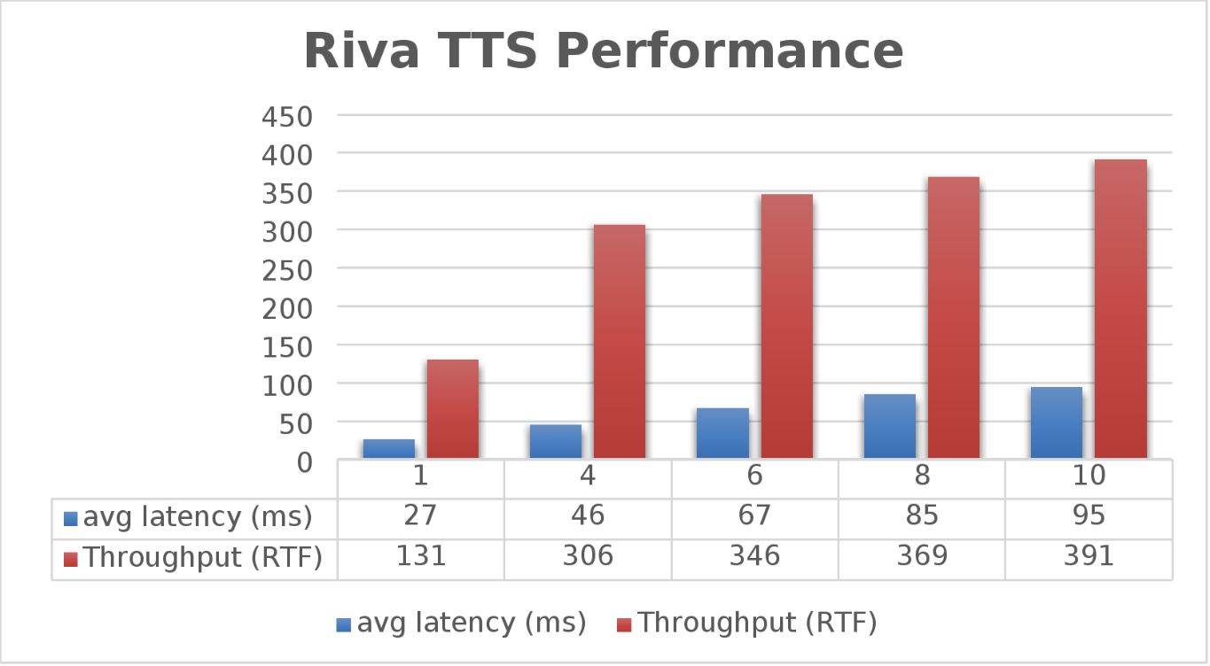 Figure 2. NVIDIA Riva TTS Performance
Again, the goal is to have a low average latency with a high throughput. The throughput (RTFX) in this case is the duration of audio generated divided by computation time. As we can see, this results in a RTFX throughput of 391 with a latency of 91ms with ten streams. It is also worth noting that during testing, GPU utilization was approximately 82% with no storage bottlenecks.
This is a lot of data to pack into one poster. Luckily, the Dell PowerFlex Solutions Engineering team created a validated architecture that details how all of these results were achieved and how an organization could replicate them if needed.
Now, to put all this into perspective, with PowerFlex you can achieve great results on both spoken language coming into your organization and converting text to speech. Pair this capability with some other generative AI (genAI) tools, like NVIDIA NeMo, and you can create some ingenious systems for your organization.
For example, if an ASR model is paired with a large language model (LLM) for a help desk, users could ask it questions verbally, and—once it found the answers—it could use TTS to provide them with support. Think of what that could mean for organizations.
It's amazing how a simple poster can hold so much information and so many possibilities. If you’re interested in learning more about the research Dell PowerFlex has done with NVIDIA Riva, visit the Poster Reception at NVIDIA GTC on Monday, March 18th from 4:00 to 6:00 PM. If you are unable to join us at the poster reception, the poster will be on display throughout NVIDIA GTC. If you are unable to attend GTC, check out the white paper, and reach out to your Dell representative for more information.
Authors: Tony Foster | Twitter: @wonder_nerd | LinkedIn
Praphul Krottapalli
Kailas Goliwadekar

Dell PowerFlex – For Business-Critical Workloads and AI
Wed, 21 Feb 2024 00:10:52 -0000
|Read Time: 0 minutes
AI—the buzzword that dances on the tongues of tech enthusiasts, executives, and coffee-break conversationalists alike. It's the shiny promise of automation, insights, and futuristic marvels. But let's step back from the AI dazzle for a moment. Beneath the glitz lies a fundamental truth: business-critical applications are the unsung heroes of organizational success. Enter Dell PowerFlex, the sturdy workhorse that ensures these applications run seamlessly.
The AI hype revisited
Imagine a room abuzz with anticipation. Faces lean forward, eager for the next AI revelation. If you've followed my previous blog, Can I Do That AI Thing on Dell PowerFlex, you know the answer. Yes, you can do that AI thing on PowerFlex. Being able to do AI shouldn’t be the end all be all for organizations. In fact, for most, it’s probably only a small portion of their IT operations. To that end, Dell PowerFlex isn't just built for AI. In fact, PowerFlex’s real strength isn’t AI at all.
Crushing the AI illusion
Let's peel back the layers. Dell PowerFlex isn't a mystical crystal ball, predicting stock market trends or composing poetry. Instead, it's the backbone supporting everyday business operations. Think databases, application servers, file servers—the workhorses that keep your organization humming. These workloads are the lifeblood of any enterprise, and their smooth functioning is non-negotiable. For many organizations, AI operations are a distant second. Why not optimize for the workhorses as well as prepare to support that new AI model?
The workload warriors
- Databases: Customer data, financial records, and inventory details all reside in databases. Dell PowerFlex ensures their availability, scalability, and performance.
- Application Servers: The engines behind web applications, APIs, and services. PowerFlex flexes its muscles here, providing the horsepower needed for user requests, transactions, and data processing.
- File Servers: Shared drives, document repositories, and collaboration spaces rely on file servers. PowerFlex ensures your files flow smoothly, whether you're sharing a presentation or collaborating on a project.
- And So Many Others: ERP systems, CRM platforms, virtual desktops—the list goes on. Each workload has its quirks, demands, and deadlines. Dell PowerFlex steps up, offering a unified platform that simplifies management and boosts performance.
Business-critical, Dell PowerFlex vital
These business-critical workloads are the heartbeat of organizations. They power customer interactions, financial transactions, and strategic decision-making. When these workloads hiccup, the entire operation feels it. That's where Dell PowerFlex shines. Its architecture leverages a robust and resilient software-defined storage (SDS) platform. Translation? It's agile, scalable, and resilient.
So, what's the secret sauce? PowerFlex leverages distributed storage resources, creating a pool of compute and storage nodes. These nodes collaborate harmoniously, distributing data and handling failures gracefully. Whether you're running a database query, serving up a web page, or analyzing mountains of data, PowerFlex ensures the show goes on.
The PowerFlex promise
Dell PowerFlex isn't just a hardware box—it's a promise. A promise to keep your workloads humming, your data secure, and your business thriving. So, the next time AI dazzles you with its potential, remember that PowerFlex is the sturdy engine of reliability in the background, ensuring the lights stay on, the servers stay responsive, and the wheels of progress keep turning.
In the grand scheme of IT, Dell PowerFlex takes center stage—an unassuming force that holds everything together. And as we navigate the AI landscape, let's tip our hats to the real heroes who keep the gears turning, one workload—AI included—at a time.
In the interest of full disclosure, this blog was created with the assistance of AI.
Author: Tony Foster
Twitter: @wonder_nerd
LinkedIn

PowerFlex and CloudStack, an Amazing IaaS match!
Sat, 18 Nov 2023 14:13:00 -0000
|Read Time: 0 minutes
Have you heard about Apache CloudStack? Did you know it runs amazingly on Dell PowerFlex? And what does it all have to do with infrastructure as a service (IaaS)? Interested in learning more? If so, then you should probably keep reading!
The PowerFlex team and ShapeBlue have been collaborating to bring ease and simplicity to CloudStack on PowerFlex. They have been doing this for quite a while. As new versions are released, the teams work together to ensure it continues to be amazing for customers. The deep integration with PowerFlex makes it an ideal choice for organizations building CloudStack environments.
Both Dell and ShapeBlue are gearing up for the CloudStack Collaboration Conference (CCC) in Paris on November 23 and 24th. The CloudStack Collaboration Conference is the biggest get-together for the Apache CloudStack Community, bringing vendors, users, and developers to one place to discuss the future of open-source technologies, the benefits of CloudStack, new integrations, and capabilities.
CloudStack is open-source software designed to deploy and manage large networks of virtual machines as a highly available, highly scalable Infrastructure as a Service (IaaS) cloud computing platform. CloudStack is used by hundreds of service providers around the world to offer public cloud services and by many companies to provide an on-premises (private) cloud offering or as part of a hybrid cloud solution.
Users can manage their cloud with an easy to use Web interface, command line tools, and/or a full-featured RESTful API. In addition, CloudStack provides an API that is compatible with AWS EC2 and S3 for organizations that want to deploy hybrid clouds.
CloudStack can leverage the extensive PowerFlex REST APIs to enhance functionality. This facilitates streamlined provisioning, effective data management, robust snapshot management, comprehensive data protection, and seamless scalability, making the combination of PowerFlex storage and CloudStack a robust choice for modern IaaS environments.
You can see this in the following diagram. CloudStack and PowerFlex communicate with each other using APIs to coordinate operations for VMs. This makes it easier to administer larger environments, enabling organizations to have a true IaaS environment.
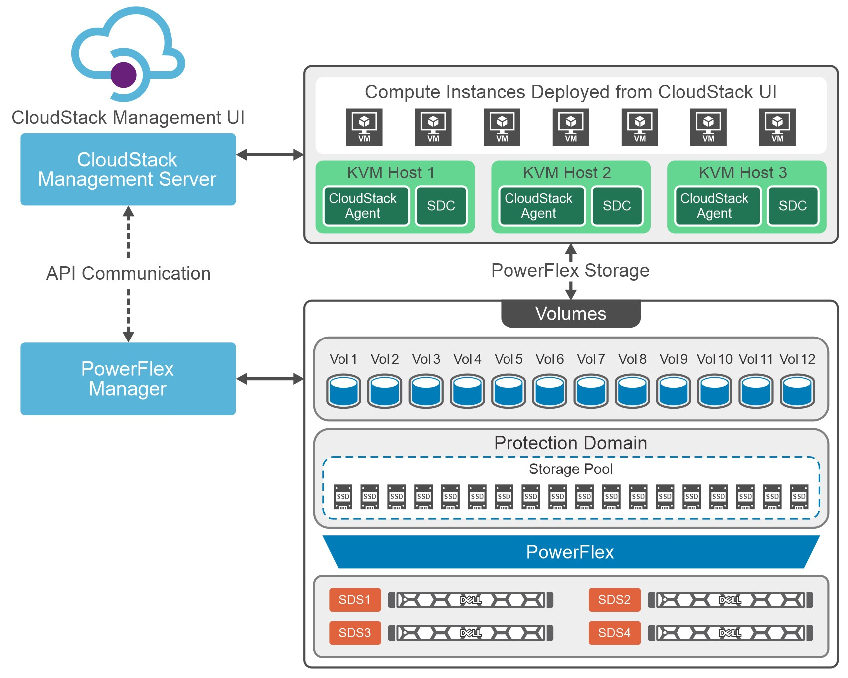
Figure 1. Cloud Stack on PowerFlex Architecture
Let's talk about IaaS for a moment. It is a fantastic concept that can be compared with ordering off a menu at a restaurant. The restaurant has unrelated dishes on the menu until you start looking at their components. For example, you can get three different base sauces (red, pink, and white) with just a red sauce and a white sauce. With a small variety of pasta and proteins, the options are excellent. This is the same for IaaS. Have a few base options, sprinkle on some API know-how, and you get a fantastic menu to satisfy workload needs without having a detailed knowledge of the infrastructure.
That makes it easier for the IT organization to become more efficient and shift the focus toward aspirational initiatives. This is especially true when CloudStack and PowerFlex work together. The hungry IT consumers can get what they want with less IT interaction.
Other significant benefits that come from integrating CloudStack with PowerFlex include the following:
- Seamless Data Management: Efficient provision, backup, and data management across infrastructure, ensuring data integrity and accessibility.
- Enhanced Performance: Provides low-latency access to data, optimizing I/O, and reducing bottlenecks. This, in turn, leads to improved application and workload performance.
- Reliability and Data Availability: Benefit from advanced redundancy and failover mechanisms and data replication, reducing the risk of data loss and ensuring continuous service availability.
- Scalability: Scalable storage solutions allow organizations to expand their storage resources in tandem with their growing needs. This flexibility ensures that they can adapt to changing workloads and resource requirements.
- Simplified Management: Ability to use a single interface to handle provisioning, monitoring, troubleshooting, and streamlining administrative tasks.
- Enhanced Data Protection: Data protection features, such as snapshots, backups, and disaster recovery solutions. This ensures that an organization's data remains secure and can be quickly restored in case of unexpected incidents.
These are tremendous benefits for organizations, especially the data protection aspects. It is often said that it is no longer a question of if an organization will be impacted by an incident. It is a question of when they will be impacted. The IaaS capabilities of CloudStack and PowerFlex play a crucial role in protecting an organization's data. That protection can be automated as part of the IaaS design. That way, when a VM or VMs are requested, they can be assigned to a data protection policy as part of the creation process.
Simply put, that means that VM can be protected from the moment of creation. No more having to remember to add a VM to a backup, and no more "oh no" when someone realizes they forgot. That is amazing!
If you are at the CloudStack Collaboration Conference and are interested in discovering more, talk with Shashi and Florian. They will also present how CloudStack and PowerFlex create an outstanding IaaS solution.
Register for the CloudStack Collaboration Conference here to join virtually if you are unable to attend in person.
If you want to learn more about how PowerFlex and CloudStack can benefit your organization, reach out to your Dell representative for more details on this amazing solution.
Resources
Authors
Tony Foster
Twitter: @wonder_nerd
LinkedIn
Punitha HS
LinkedIn

PowerFlex: CloudIQ Enhancements
Thu, 16 Nov 2023 22:07:06 -0000
|Read Time: 0 minutes
Have you checked out the All Features and Updates dialog in CloudIQ recently? If not, then let’s take a look together!
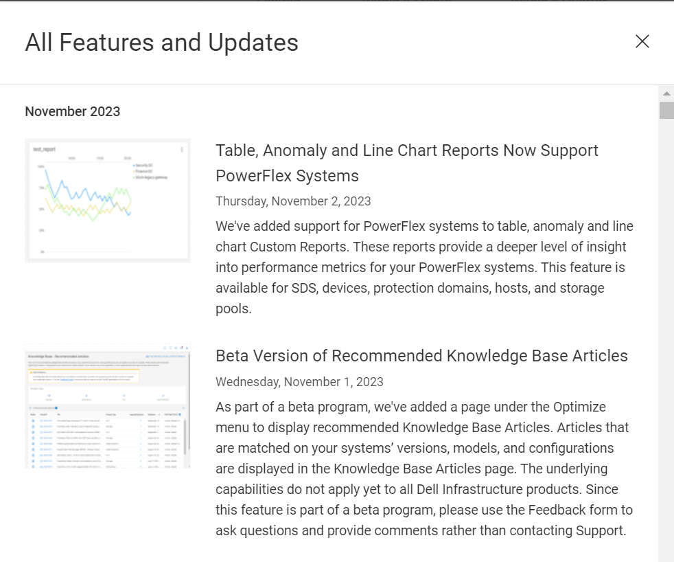
Figure 1. All Features and Updates dialog in CloudIQ
The first enhancement happened early this year with the addition of PowerFlex alerts. The alerts can be viewed through the System Alerts tile on the Home page, shown in figure 2, or by selecting Alerts under the Monitor menu. The System Alerts tile provides an alert count by severity level for all systems monitored by CloudIQ. Selecting the severity icon in the System Alerts tile redirects you to the Alerts page with a filter applied based on the selected severity.
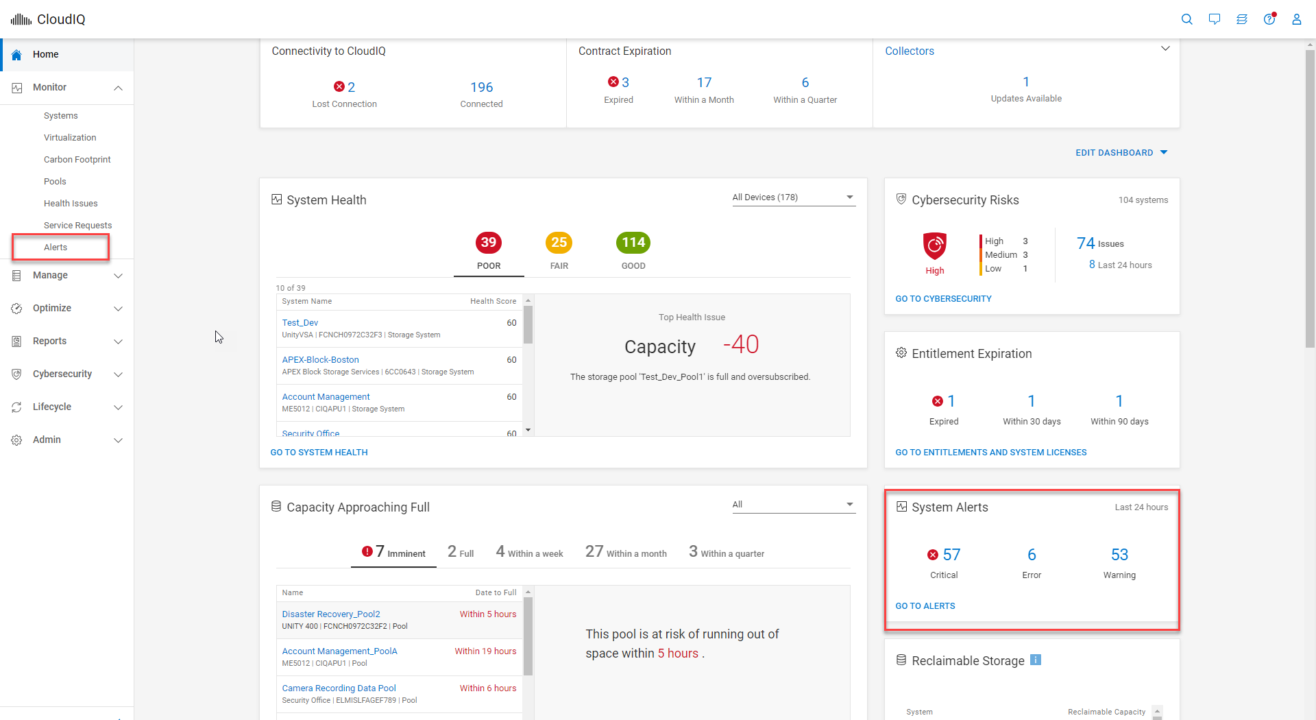
Figure 2. System Alerts tile within CloudIQ Home page
Once on the Alerts page, you can apply additional filters. The Alerts page has a simple table layout and displays information such as severity, system name, and model alert description, as well as the date and time when the alert occurred. Details of an alert can be viewed by selecting the details icon, as highlighted in figure 3.
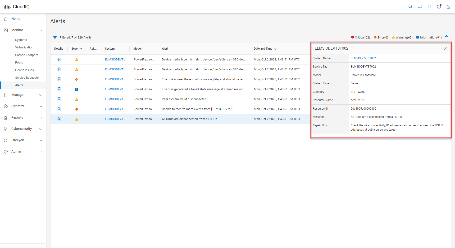
Figure 3. Details expanded for CloudIQ alert
In August, the PowerFlex/CloudIQ engineering team was busy releasing a bunch of exciting updates.
CloudIQ now supports Secure Connect Gateways (SCG) for PowerFlex systems. You can view the SCG information at a system level by visiting the PowerFlex system details page and clicking the GATEWAYS tab, highlighted in figure 3. The GATEWAYS tab consists of the gateway serial number, site information, location, gateway version, connectivity status, and heartbeat status.
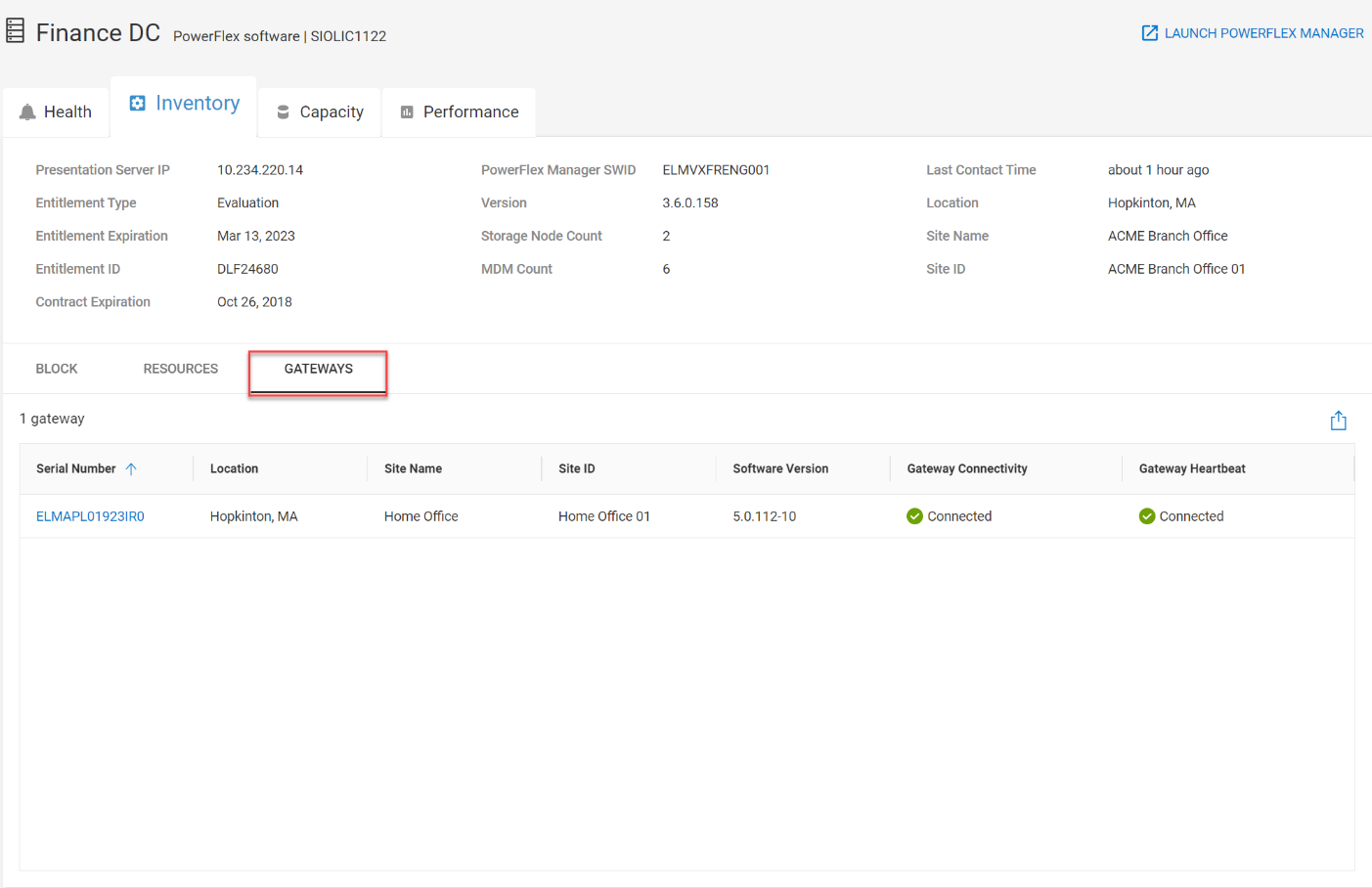
Figure 4. GATEWAYS tab for Finance DC PowerFlex system
The SCG serial number links to the SCG details page shown in figure 5. All systems connected to the specific SCG are listed on the SCG details page. From here, you can launch the SCG UI by clicking the link at the upper right corner of the page, providing a seamless workflow when working with the gateway from CloudIQ.
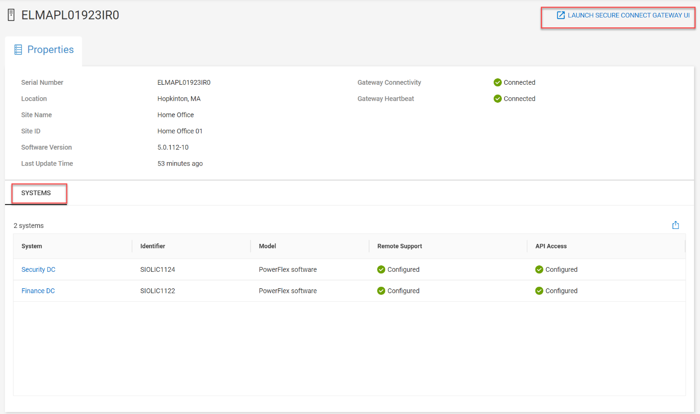
Figure 5. SCG details page highlighting connected systems and the SCG UI launch
A Gateway column was added to the Admin>Connectivity page. The most recently active gateway for the PowerFlex system is listed in this column and contains a link to the gateway details page.
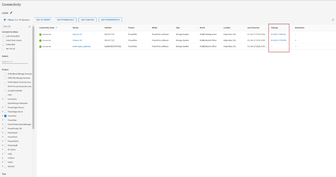
Figure 6. Gateway column on the Connectivity page
The next update is the Entitlements and System Licenses page, which you can find in the Admin section under Licenses. Here, you can check on the entitlements and licenses for all your PowerFlex systems. For more on this update, refer to the blog, Managing Dell PowerFlex Licensing and Being Way Less Sad.
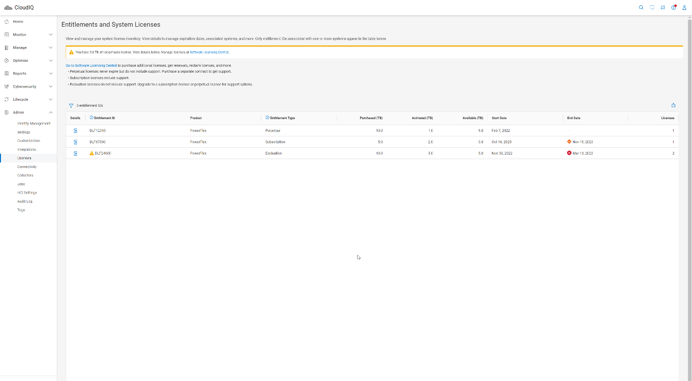
Figure 7. Entitlements and System Licenses page
A new Entitlements tile is now available on the CloudIQ Home page, providing a summary of entitlement status. The Entitlements tile lets you quickly view the number of PowerFlex systems with entitlements and licenses that are expired, expiring withing 30 days, and expiring within 90 days.
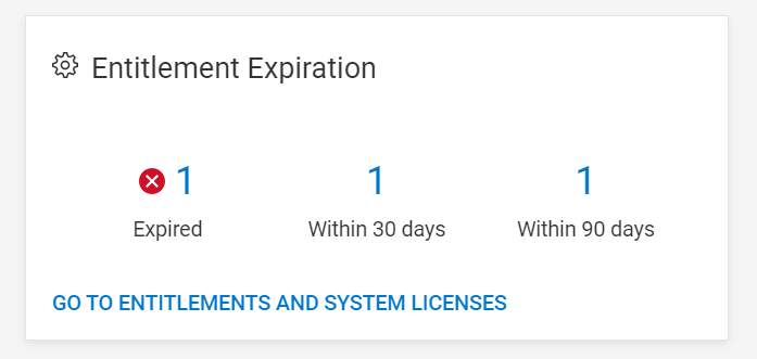
Figure 8. Entitlement Expiration tile on CloudIQ Home page
Another location for entitlement and contract status is on the PowerFlex Systems tiles. An entitlement that is in good standing is marked with a green checkmark, soon to expire with a yellow icon, and expired with a red “x.”
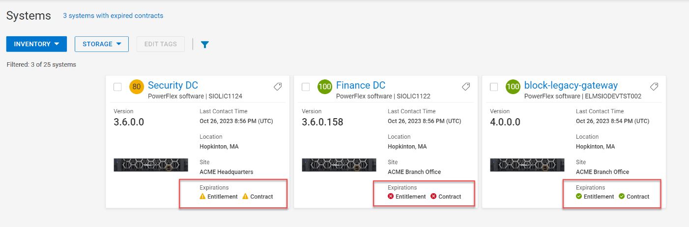
Figure 9. Three entitlement and contract statuses in PowerFlex Systems tile
MDM cluster information was added to CloudIQ in July of this year. To view the MDM information, go to the system details page for the PowerFlex system and select the RESOURCES tab, shown in figure 10. You can view a list of the MDMs, MDM role, ID, management IP addresses, and software version.
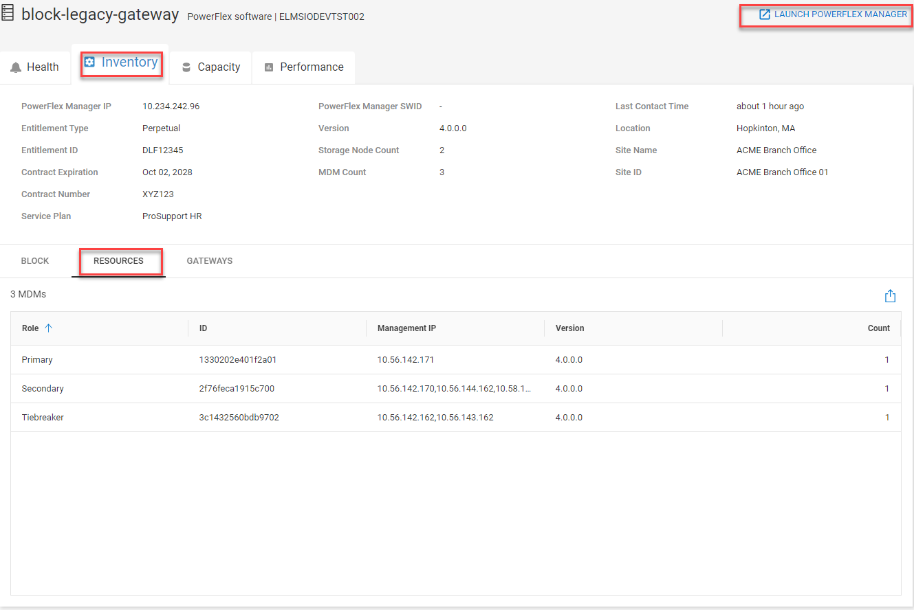
Figure 10. PowerFlex system details page highlighting the RESOURCES tab under Inventory and the PowerFlex Manager launch
Another addition to the system details page is a link to PowerFlex Manager, making it convenient to launch the PowerFlex Manager UI for the specified system. A BLOCK tab provides details on PowerFlex components, including protection domains, fault sets, SDSs, devices, storage pools, volumes, and hosts. The views may feel familiar to you because they are based on the Block menu in PowerFlex Manager.
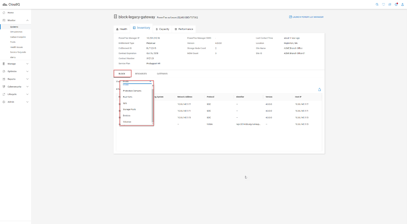
Figure 11. BLOCK tab within PowerFlex system details page
Planning on adopting APEX Block Storage for Public Cloud as part of your Multicloud strategy? CloudIQ has you covered on-prem and in the cloud.
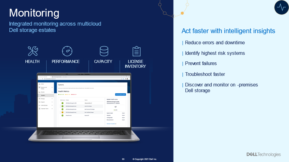
Figure 12. CloudIQ Monitoring overview
Onboarding your APEX Block Storage for Public Cloud into CloudIQ brings visibility into the cloud infrastructure.
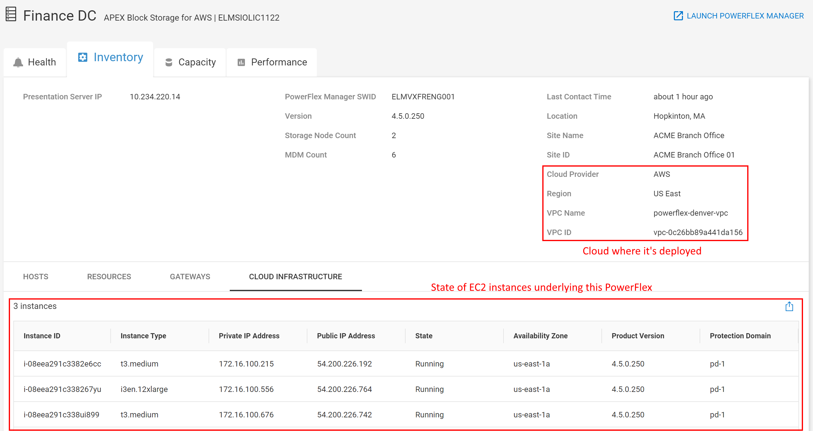
Figure 13. Inventory page for APEX Block Storage for AWS
The last enhancement that I will highlight is the addition of PowerFlex in custom reports. This update provides three report types, including anomaly charts, line charts, and table reports.
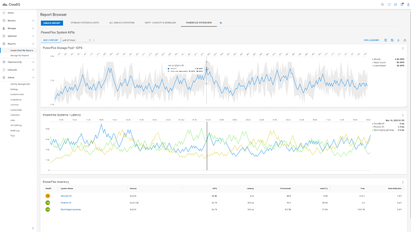
Figure 14. Three report types in a custom report for PowerFlex
The anomaly chart consists of a single performance metric overlaid on the gray historic seasonality value boundaries. The upper and lower bounds establish the normal behavior for the specific metric. The bounds are based on an analysis of the prior three-week history. Historical values that exceed the upper or lower bounds are shaded in light blue to highlight that the value of the metric during this time was outside the historical range. Anomaly charts, at most, display the last 24 hours of data. The line chart allows you to display more than one metric from one or more systems. The example in figure 14 shows system latency from three PowerFlex systems. The table displays metrics and properties, such as system name and code version.
The next time you are working with CloudIQ, keep an eye out for the latest enhancements. If you have not onboarded your PowerFlex systems into CloudIQ, check out the PowerFlex CloudIQ onboarding article to get started.
Resources
Procedure to Onboard PowerFlex Systems to CloudIQ
Author: Roy Laverty, Principal Technical Marketing Engineer
Twitter: @RoyLaverty
LinkedIn: https://linkedin.com/in/roy-laverty

Using Dell PowerFlex and Google Distributed Cloud Virtual for Postgres Databases and How to Protect Them

Fri, 03 Nov 2023 23:27:04 -0000
|Read Time: 0 minutes
Did you know you can get the Google Cloud experience in your data center? Well now, you can! Using Google Distributed Cloud (GDC) Virtual and Dell PowerFlex enables the use of cloud and container workloads – such as Postgres databases – in your data center.
Looking beyond day one operations, the whole lifecycle must be considered, which includes assessing how to protect these cloud native workloads. That’s where Dell PowerProtect Data Manager comes in, allowing you to protect your workloads both in the data center and the cloud. PowerProtect Data Manager enhances data protection by discovering, managing, and sending data directly to the Dell PowerProtect DD series virtual appliance, resulting in unmatched efficiency, deduplication, performance, and scalability. Together with PowerProtect Data Manager, the PowerProtect DD is the ultimate cyber resilient data protection appliance.
In the following blog, we will unpack all this and more, giving you the opportunity to see how Dell PowerFlex and GDC Virtual can transform how you cloud.
What is Google Distributed Cloud Virtual?
We will start by looking at GDC Virtual and how it allows you to consume the cloud on your terms.
GDC Virtual provides you with a consistent platform for building and managing containerized applications across hybrid infrastructures and helps your developers become more productive across all environments. GDC Virtual provides all the mechanisms required to bring your code into production reliably, securely, and consistently while minimizing risk. GDC Virtual is built on open-source technologies pioneered by Google Cloud including Kubernetes and Istio, enabling consistency between cloud and on premises environments like PowerFlex. Anthos GKE (on GCP and on-prem), Anthos Service Mesh, and Anthos Config Management are the core building blocks of Anthos, which has integrations with platform-level services such as Stackdriver, Cloud Build, and Binary Authorization. GDC Virtual users purchase services and resources from the GCP Marketplace.
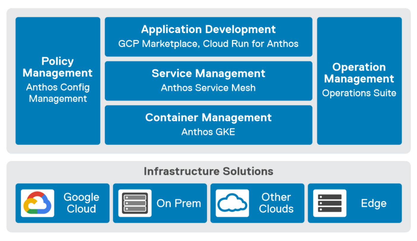
Figure 1. GDC Virtual components.
GDC Virtual puts all your IT resources into a consistent development, management, and control framework, automating low-value tasks across your PowerFlex and GCP infrastructure.
Within the context of GCP, the term ‘hybrid cloud’ describes a setup in which common or interconnected services are deployed across multiple computing environments, which include public cloud and on-premises. A hybrid cloud strategy allows you to extend the capacity and capabilities of your IT without the upfront capital expense investments of the public cloud while preserving your existing investments by adding one or more cloud deployments to your existing infrastructure. For more information, see Hybrid and Multi-Cloud Architecture Patterns.
PowerFlex delivers software defined storage to both virtual environments and bare metal hosts providing flexible consumption or resources. This enables both two-tier and three-tier architectures to match the needs of most any environment.
PowerFlex container storage
From the PowerFlex UI – shown in the following figure – you can easily monitor the performance and usage of your PowerFlex environment. Additionally, PowerFlex offers a container storage interface (CSI) and container storage modules (CSM) for integration with your container environment. The CSI/CSM allows containers to have persistent storage, which is important when working with workloads like databases that require it.
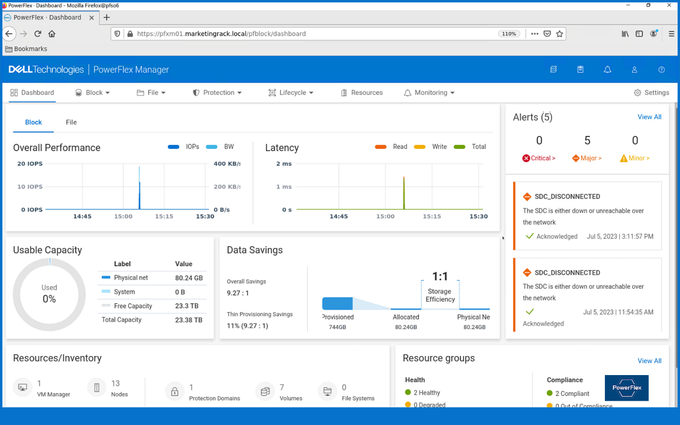
Figure 2. PowerFlex dashboard provides easy access to information.
To gain a deeper understanding of implementing GDC Virtual on Dell Powerflex, we invite you to explore our recently published reference architecture.
Dell engineers have recently prepared a PostgreSQL container environment deployed from the Google Cloud to a PowerFlex environment with GDC Virtual in anticipation of Kubecon. For those who have deployed Postgres from Google Cloud, you know it doesn’t take long to deploy. It took our team maybe 10 minutes, which makes it effortless to consume and integrate into workloads.
Once we had Postgres deployed, we proceeded to put it under load as we added records to it. To do this, we used pgbench, which is a built-in benchmarking tool in Postgres. This made it easy to fill a database with 10 million entries. We then used pgbench to simulate the load of 40 clients running 40 threads against the freshly loaded database.
Our goal wasn’t to capture performance numbers though. We just wanted to get a “warm” database created for some data protection work. That being said, what we saw on our modest cluster was impressive, with sub-millisecond latency and plenty of IO.
Data protection
With our containerized database warmed up, it was time to protect it. As you probably know, there are many ways to do this, some better than others. We’ll spend just a moment talking about two functional methods of data protection – crash consistent and application consistent backups. PowerProtect Data Manager supports both crash-consistent and application consistent database backups.
A “crash consistent” backup is exactly as the name implies. The backup application captures the volume in its running state and copies out the data regardless of what’s currently happening. It’s as if someone had just pulled the power cord on the workload. Needless to say, that’s not the most desirable backup state, but it’s still better than no backup at all.
That’s where an “application consistent” backup can be more desirable. An application consistent backup talks with the application and makes sure the data is all “flushed” and in a “clean” state prior to it being backed up. At least, that’s the simple version.
The longer version is that the backup application talks to the OS and application, asks them to flush their buffers – known as quiescing – and then triggers a snapshot of the volumes to be backed up. Once complete, the system then initiates a snapshot on the underlying storage – in this case PowerFlex – of the volumes used. Once the snapshots are completed, the application-level snapshots are released, the applications begin writing normally to it again, and the backup application begins to copy the storage snapshot to the protected location. All of this happens in a matter of seconds, many times even faster.
This is why application consistent backups are preferred. The backup can take about the same amount of time to run, but the data is in a known good state, which makes the chances of recovery much greater than crash consistent backups.
In our lab environment, we did this with PowerProtect Data Manager and PowerProtect DD Virtual Edition (DDVE). PowerProtect Data Manager provides a standardized way to quiesce a supported database, backup the data from that database, and then return the database to operation. This works great for protecting Kubernetes workloads running on PowerFlex. It’s able to create application consistent backups of the Postgres containers quickly and efficiently. This also works in concert with GDC Virtual, allowing for the containers to be registered and restored into the cloud environment.
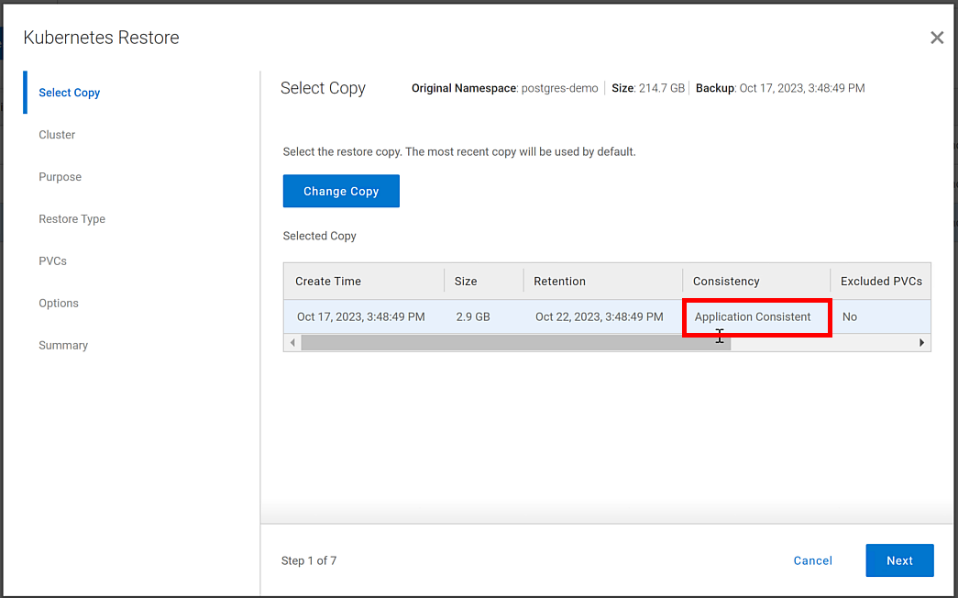
Figure 3. An application consistent backup and its timing in the PowerProtect Data Manager UI
It’s great having application consistent backups of your cloud workloads, “checking” many of those boxes that people require from their backup environments. That said, just as important and not to be forgotten is the recovery of the backups.
Data recovery
As has been said many times, “never trust a backup that hasn’t been tested.” It’s important to test any and all backups to make sure they can be recovered. Testing the recovery of a Postgres database running in GDC Virtual on PowerFlex is as straightforward as can be.
The high-level steps are:
- From the PowerProtect Data Manager UI, select Restore > Assets, and select the Kubernetes tab. Select the checkbox next to the protected namespace and click Restore.
- On the Select Copy page, select the copy you wish to restore from.
- On the Restore Type page, select where it should be restored to.
- Determine how the Persistent Volume Claims (PVCs) and namespace should be restored.
- When finished, test the restore.
You might have noticed in step 4, I mentioned PVCs, which are the container’s connections to the data and, as the name implies, allow that data to persist across the nodes. This is made possible by the CSI/CSM mentioned earlier. Because of the integration across the environment, restoring PVCs is a simple task.
The following shows some of the recovery options in PowerProtect Data Manager for PVCs.
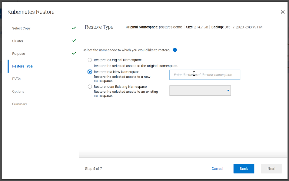
Figure 4. PowerProtect Data Manager UI – Namespace restore options
The recovery, like most things in data protection, is relatively anticlimactic. Everything is functional, and queries work as expected against the Postgres database instance.
Dell and Google Cloud collaborated extensively to create solutions that leverage both PowerFlex and GDC Virtual. The power of this collaboration really shows through when recovery operations just work. That consistency and ease enables customers to take advantage of a robust environment backed by leaders in the space and helps to remove one nightmare that keeps developers and IT admins awake at night, allowing them to rest easy and be prepared to change the world.
If any of this sounds interesting to you and you’ll be at Kubecon in Chicago, Illinois on November 6-9, stop by the Google Cloud booth. We’ll be happy to show you demos of this exciting collaboration in action. Otherwise, feel free contact your Dell representative for more details.
Resources
Authors:
Authors: | Tony Foster, | Vinod Kumar Kumaresan, | Harsha Yadappanavar, |
LinkedIn: | |||
X (formerly Twitter): |
| @harshauy | |
Personal Blog: |
|
|

KubeCon NA23, Google Cloud Anthos on Dell PowerFlex and More
Sun, 05 Nov 2023 23:26:43 -0000
|Read Time: 0 minutes
KubeCon will be here before you know it. There are so many exciting things to see and do. While you are making your plans, be sure to add a few things that will make things easier for you at the conference and afterwards.
Before we get into those things, did you know that the Google Cloud team and the Dell PowerFlex team have been collaborating? Recently Dell and Google Cloud published a reference architecture: Google Cloud Anthos and GDC Virtual on Dell PowerFlex. This illustrates how both teams are working together to enable consistency between cloud and on premises environments like PowerFlex. You will see this collaboration at KubeCon this year.
On Tuesday at KubeCon, after breakfast and the keynote, you should make your way to the Solutions Showcase in Hall F on Level 3 of the West building. Once there, make your way over to the Google Cloud booth and visit with the team! They want your questions about PowerFlex and are eager to share with you how Google Distributed Cloud (GDC) Virtual with PowerFlex provides a powerful on-premises container solution.
Also, be sure to catch the lightning sessions in the Google Cloud booth. You’ll get to hear from Dell PowerFlex engineer, Praphul Krottapalli. He will be digging into leveraging GDC Virtual on PowerFlex. That’s not the big thing though, he’ll also be looking at running a Postgres database distributed across on-premises PowerFlex nodes using GDC Virtual. Beyond that, they will look at how to protect these containerized database workloads. They’ll show you how to use Dell PowerProtect Data Manager to create application consistent backups of a containerized Postgres database instance.
We all know backups are only good if you can restore them. So, Praphul will show you how to recover the Postgres database and have it running again in no time.
Application consistency is an important thing to keep in mind with backups. Would you rather have a database backup where someone had just pulled the plug on the database (crash consistent) or would you like the backup to be as though someone had gracefully shut down the system (application consistent)? For all kinds of reasons (time, cost, sanity), the latter is highly preferable!
We talk about this more in a blog that covers the demo environment we used for KubeCon.
This highlights Dell and Google’s joint commitment to modern apps by ensuring that they can be run everywhere and that organizations can easily develop and deploy modern workloads.
If you are at KubeCon and would like to learn more about how containers work on Dell solutions, be sure to stop by both the Dell and Google Cloud booths. If it’s after KubeCon, be sure to reach out to your Dell representative for more details.
Author: Tony Foster

Dell PowerFlex at VMware Explore in Barcelona – Nothing Controversial
Thu, 19 Oct 2023 22:38:22 -0000
|Read Time: 0 minutes
For those who aren’t aware, there are some big changes happening at VMware. If you watched the VMware Explore Las Vegas keynote, it was a whirlwind of changes and important information. CEOs of several major companies took the stage and spoke about the direction VMware is going, attendees hanging on their every word and wondering what the changes meant as well as how it would impact their operations.
For many, the impact is still unclear. This could radically change data centers and how organizations do work, leaving many in IT and business asking questions about what’s next and where things are headed.
We can all expect to find out more at VMware Explore Barcelona coming up 6 to 9 November, which will bring more clarity in direction and illuminate what it will mean for organizations large and small.
I can’t wait to see what’s in store for the Generative AI (GenAI) workloads we’ve all been waiting for (And you thought I was talking about something else?).
At VMware Explore in Las Vegas this year, the message was clear. VMware is embracing AI workloads. NVIDIA CEO Jensen Huang and VMware CEO Raghu Raghuram spoke to this during the general session keynote. Jensen stated, “we’re reinventing enterprise computing after a quarter of a century in order to transition to the future.”
The entire IT industry is moving in the direction of AI. Dell PowerFlex is already there. We’ve been on this journey for quite some time. If you were lucky enough to have stopped at the Kioxia stand during the Las Vegas show, you saw how we are working with both NVIDIA and Kioxia to deliver powerful AI systems for customers to make that transition to the future.
If you couldn’t make it to Las Vegas for VMware Explore but plan to attend VMware Explore in Barcelona, you’re in luck. PowerFlex will be showcasing the amazing performance of Kioxia storage and NVIDIA GPUs again. You can see a live demo at the Kioxia stand, #225 in the Solutions Exchange.
When you visit the Kioxia stand, you will be able to experience the power of running ResNet 50 image classification and Online Transactional Processing (OLTP) workloads simultaneously, live from the show floor. And if that’s not enough, there are experts and lots of them! If you get a chance, talk with Shashi about all the things PowerFlex unlocks for your organization.
PowerFlex supports NVIDIA GPUs with MIG technology, which is part of NVIDIA AI Enterprise. NVIDIA MIG allows you to tailor GPU resources for the workloads that need them (Yes, there is nothing that says you can’t run different workloads on the same hosts). Plus, PowerFlex uses Kioxia PM7 series SSDs, so there are plenty of IOPS to go around while ensuring sub-millisecond latency for both workloads. This allows the data to be closer to the processing, even on the same host.
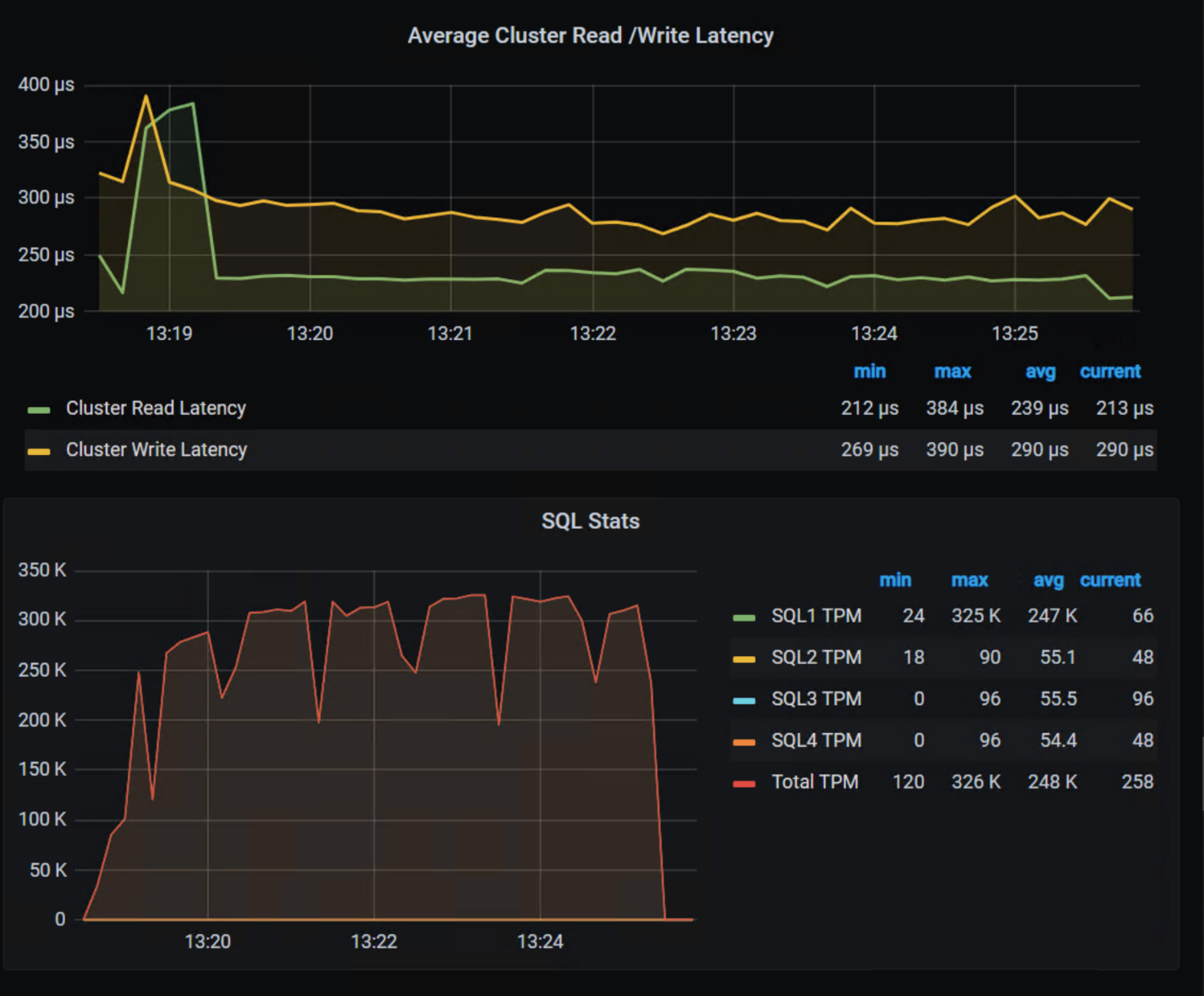
In our lab tests, we were able to push one million transactions per minute (TPM) with OLTP workloads while also processing 6620 images per second using a RESNET50 model built on NVIDIA NGC containers. These are important if you want to keep users happy, especially as more and more organizations want to add AI/ML capabilities to their online apps (and more and more data is generated from all those new apps).
The following shows the TPM results from the demo environment that is running our four SQL VMs. The TPMs in this test are maxing out around 320k, and the latency is always sub-millisecond.

The future is here and waiting for you to visit.
If you are unable to visit the stand and would like to get an overview of PowerFlex’s abilities when it comes to GenAI, check out this video.
As you can see, PowerFlex has true flexibility when it comes to GenAI, making it the ideal platform to reinvent your enterprise IT environment as you transition to the future.
If you find yourself at VMware Explore in Barcelona, be sure to stop by the Kioxia stand (#225) and talk with the team about how Dell PowerFlex, Kioxia drives, and NVIDIA GPUs can accelerate your transition to the future.
See, nothing controversial here!
Resources
- Dell Generative AI Solutions
- VMware and NVIDIA Unlock Generative AI for Enterprises
- VMware’s Approach to Private AI
Author: Tony Foster, Sr. Principal Technical Marketing Engineer
Twitter: | |
LinkedIn: | |
Personal Blog: | |
Location: | The Land of Oz [-6 GMT] |

PowerFlex: The DNA of the Ultimate Software-Defined Infrastructure
Mon, 25 Sep 2023 13:24:55 -0000
|Read Time: 0 minutes
Introduction
This blog is the first in a series discussing PowerFlex software-defined infrastructure.
PowerFlex is Dell Technologies’ flexible, resilient, and highly scalable software-defined infrastructure, providing both block and file storage services. Its software-first DNA can be traced back to influential Dell software-defined products such as ScaleIO and VxFlex.
PowerFlex software runs on the ubiquitous x86 node with TCP/IP networking, leveraging the market-leading PowerEdge server in configurations that have been tested and qualified to run PowerFlex.
Flexible consumption options
PowerFlex comes in four consumption options: PowerFlex rack, PowerFlex appliance, PowerFlex custom node, and APEX Block Storage for Public Cloud.
- PowerFlex rack is a fully engineered rack-scale system with integrated networking, management nodes, and intelligent cabinet. A turn-key solution with increased time-to-value, the value of PowerFlex rack is hard to beat.
- PowerFlex appliance provides the same level of performance as PowerFlex rack but at a smaller starting point and with greater networking options to fit a wide variety of requirements.
- PowerFlex custom node is a DIY experience compared to PowerFlex rack or PowerFlex appliance, yielding the greatest configuration flexibility of all. Custom node deployments—as the name implies—are a node level offering and do not include integrated networking.
- APEX Block Storage for Public Cloud is a deployment of the Dell software-defined block storage in the public cloud. It provides higher performance and resiliency beyond what is available with native public cloud providers.
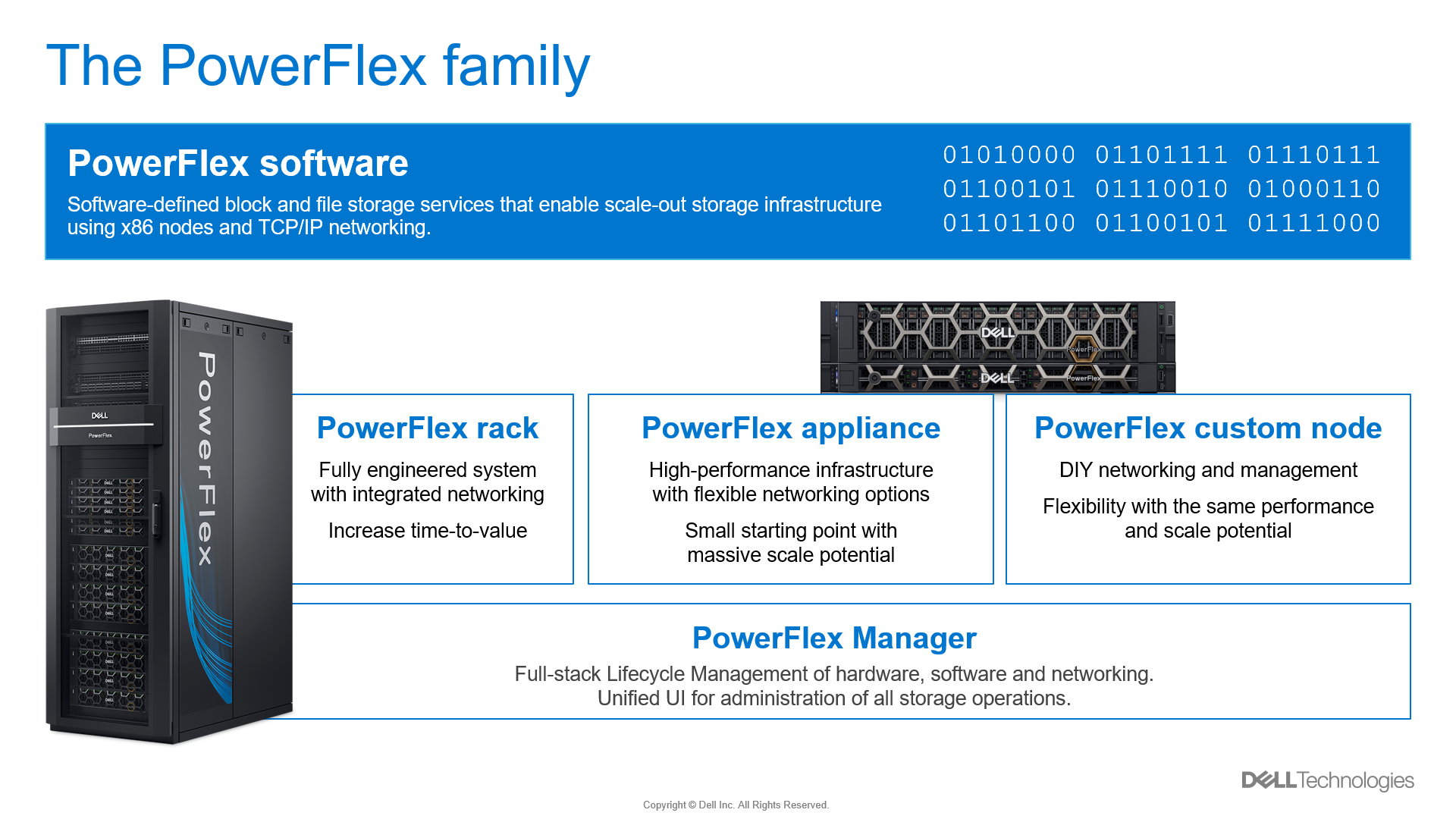
Figure 1. PowerFlex consumption options
Flexible architecture
There are three building blocks that give PowerFlex its power.
The first is the storage cluster manager called the Meta Data Manager (MDM), which sits outside of the data path. The MDM is a highly available, tightly coupled software cluster of three or five nodes, which has a supervisory role monitoring system health, managing the configuration, and coordinating the rebuilding and protection of data.
The second software component is the storage creator also known as the Storage Data Server (SDS). The SDS abstracts the local storage in each node into one or more storage pools and presents the volumes that have been provisioned from its local storage to the storage consumer.
The third component is the storage consumer called the Storage Data Client (SDC). The SDC is installed on the application node and presents the PowerFlex volume as a block device to the operating system.
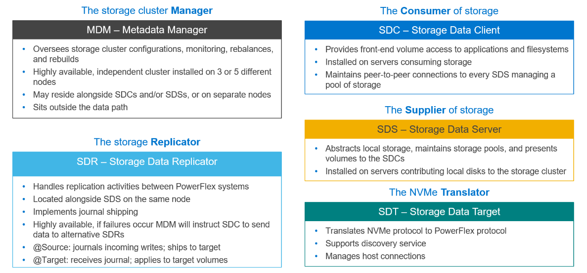
Figure 2. PowerFlex building blocks
These pieces of software can be installed on the nodes in almost any combination. How they are installed defines the role of the node in a PowerFlex system as well as the type of deployment. The following figure shows a two-layer system with a set of four storage nodes (SDS) and two compute nodes (SDC).
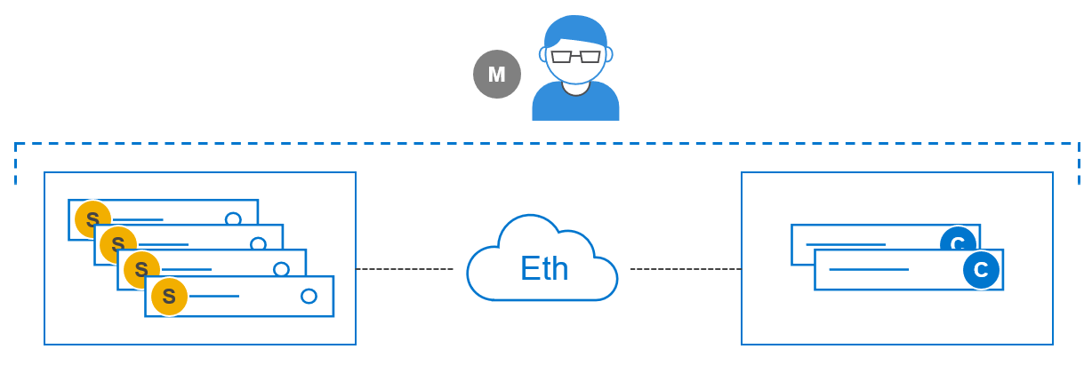
Figure 3. Two-Layer configuration
An advantage of the two-layer deployment is that we can scale the storage and compute independently. Additionally, it reduces license costs on application and compute environments that license by CPU core count. The SDC and SDS can also be installed on the same node to create an HCI deployment as shown in Figure 4, reducing complexity and resulting in increased operational efficiencies.
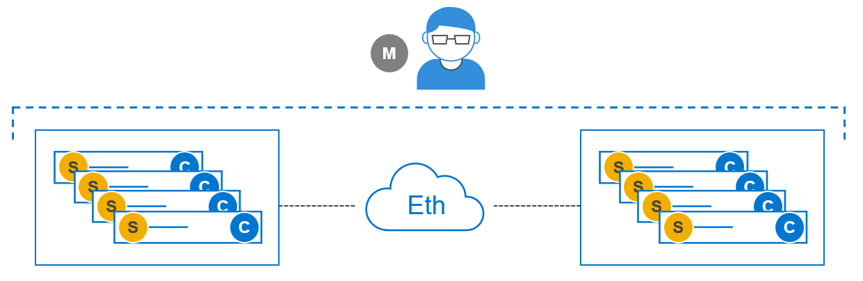
Figure 4. HCI configuration
We can also mix two-layer and HCI, all in a single PowerFlex system, as shown in Figure 5.
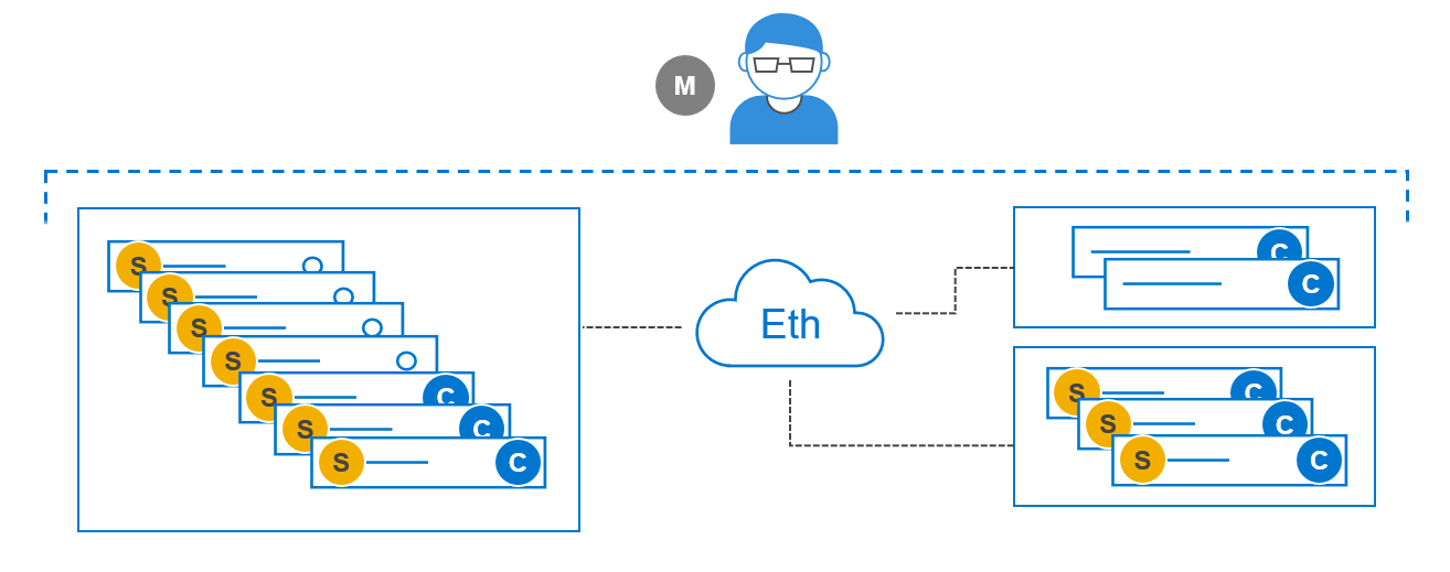
Figure 5. Mixed – Two-Layer and HCI
As you can see from the available consumption and deployment options, PowerFlex provides extreme flexibility, but it does not end there. PowerFlex boasts broad support for compute operating environments and applications, including Windows and many Linux distributions, and multiple hypervisor environments. PowerFlex is also a fantastic platform for containerized cloud native applications.
Flexibility evolved
PowerFlex is a continually evolving solution. The most recent steps in the evolution are file services, as illustrated in Figure 6, and NVMe/TCP support for front-end (application) connectivity.
PowerFlex file services use physical nodes for NAS controllers and are similar to compute nodes. When the file service is deployed, an NAS container and an SDC are installed on each dedicated file node. A single NAS cluster is supported per PowerFlex system (MDM cluster). The NAS cluster supports anything from two to sixteen physical NAS controller nodes.
The backend block storage supporting the NAS file system is PowerFlex block storage provisioned from a storage pool. Volumes are created within the selected storage pool for NAS meta data and for user file systems. PowerFlex file storage supports NFSv3/v4, SMBv2/v3, and FTP and SFTP.
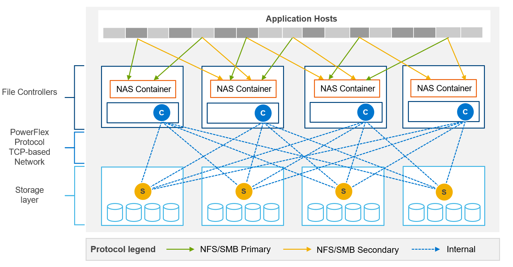
Figure 6. File services
The NVMe specification was established in 2013 to address the issue of using fast, direct, attached nonvolatile storage media with slower interfaces such as SAS. In 2016, the standard was extended to include NVMe devices used over fabrics (NVMe-oF). The SDC is not compatible with the NVMe/TCP protocol, however most operating system vendors have started to adopt NVMe/TCP natively. As such, a change in host connectivity was required to support NVMe/TCP connectivity, as illustrated in Figure 7.
I mentioned earlier that the SDC holds a map of the volume layout on the storage nodes. The map of the volume layout must be known so that reads and writes go to the appropriate SDS and device. Without an SDC, the mapping logic had to be moved from the compute node to the PowerFlex storage system. Likewise, the translation of the NVMe protocol used by the host to the proprietary PowerFlex protocol on the backend is another technical gap that needed to be filled.
Enter a new PowerFlex software module called the Storage Data Target (SDT). The SDT is installed on the storage nodes alongside the SDS and is responsible for translating the compute IO using NVMe protocol to the PowerFlex protocol. The map of the volume layout held by the SDC has been moved to the SDT.
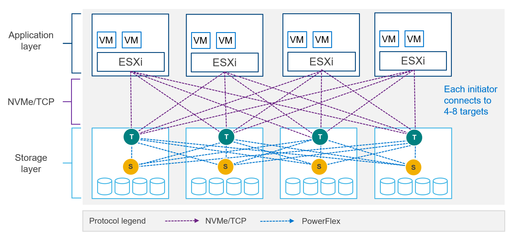
Figure 7. NVMe/TCP host connectivity
NOTE: Dell PowerFlex and most Linux distributions support NVMe/TCP in tech preview only. Consult with your operating system vendor documentation and the latest PowerFlex documentation for updated information regarding NVMe/TCP support. NVMe/TCP connectivity between VMware ESXi and Dell PowerFlex is supported.
Unmatched scalability
PowerFlex has high growth potential and can scale to thousands of nodes. You can start as small as a four-node system and add nodes as business needs dictate. Furthermore, adding nodes is a nondisruptive operation. More detailed specifications can be found in the PowerFlex Specification sheet.
Software-defined infrastructure
The SDS on each storage node abstracts the local disks and federates all of them into storage pools. In addition to aggregating the storage capacity, PowerFlex software also aggregates the performance capability of each node. For example, if one node has 20 TB of storage and can perform 100k IOPs, then two nodes provide 40 TB of storage and 200k IOPs.
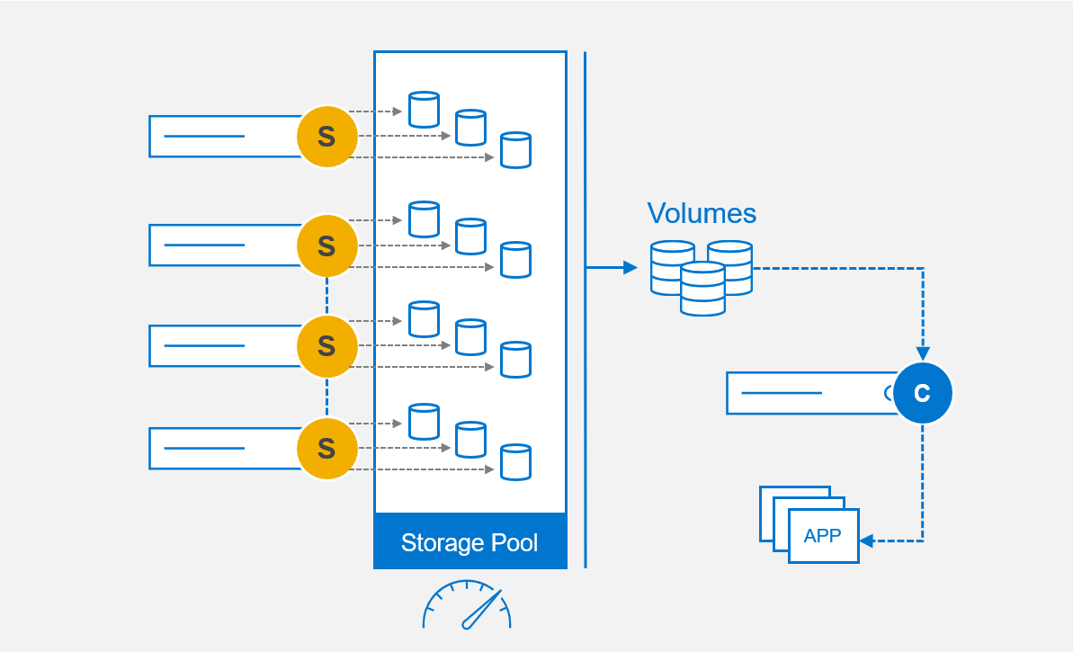
Figure 8. Software-defined infrastructure
Internal testing at Dell has shown a near linear improvement in performance when adding nodes, as displayed in Figure 9, providing predictable gains when adding nodes to a PowerFlex system.
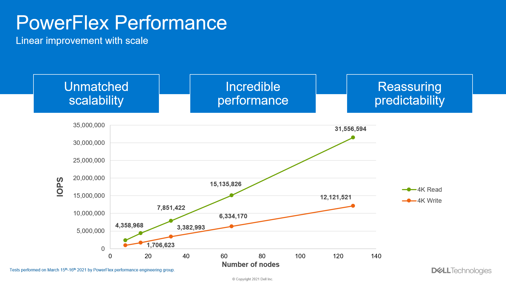
Figure 9. Linear improvement with IOPs
The same linear improvement observed with IOPs in PowerFlex is seen with throughput in Figure 10, all while maintaining submillisecond response times.
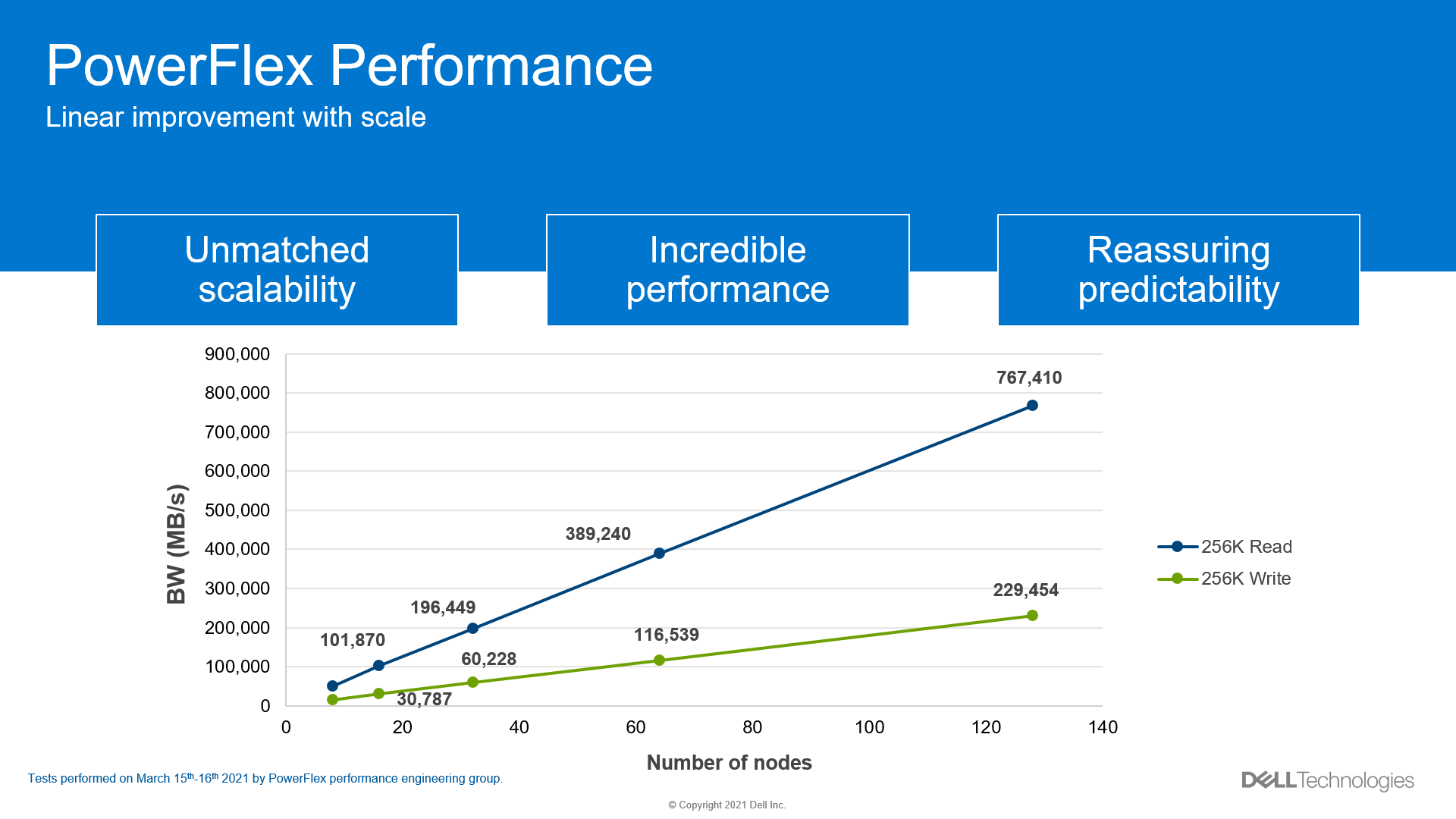
Figure 10. Linear improvement with throughput
Perfect balance
The MDM determines how to lay out the volume address space in the storage pool when it is created, as illustrated in Figure 11. The MDM sends the data map to the SDSs that are contributing storage and to the SDC that is consuming the volume. Notably, the MDM distributes the volume address space evenly across every SDS and every hard drive that is contributing storage to the storage pool.
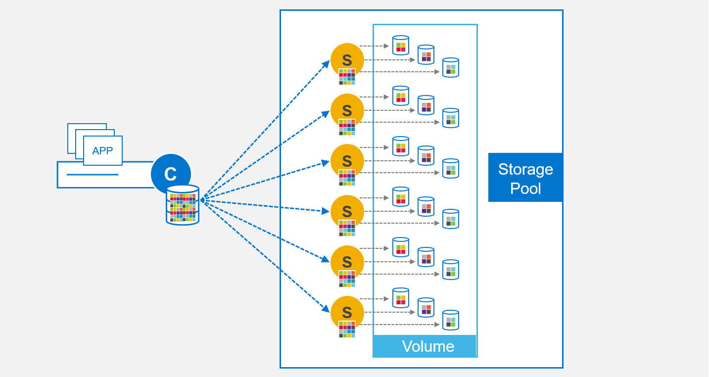
Figure 11. Volume addressing
The MDM continually monitors resources and ensures that there are no hot spots in the system. The SDSs communicate with each other over the backend mesh when an imbalance is detected and begin the process of rebalancing. This balancing act ensures capacity is evenly distributed across the backend devices and performance is distributed across the backend mesh, the result of which is displayed in Figure 12. Note that the rebalance is a background process and does not impact production IO.
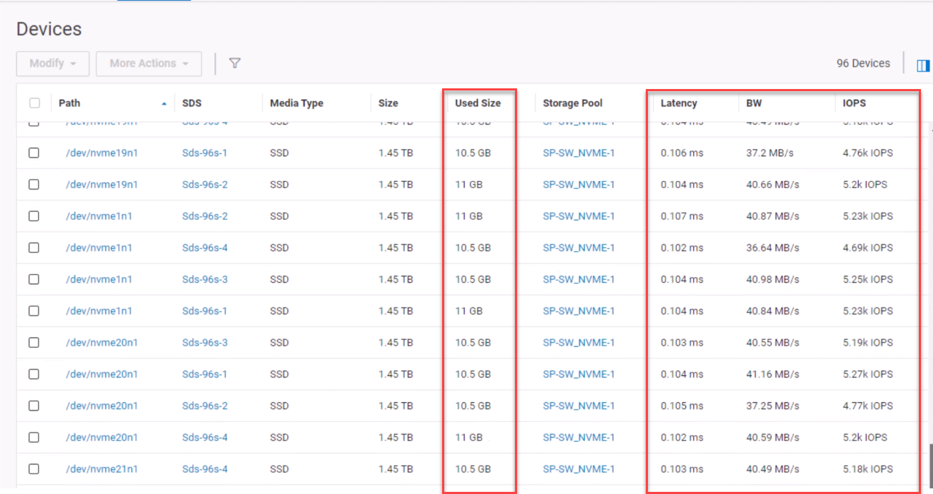
Figure 12. Balanced devices
PowerFlex also ensures that reads and writes to the volume are balanced across the SDSs in the storage pool.
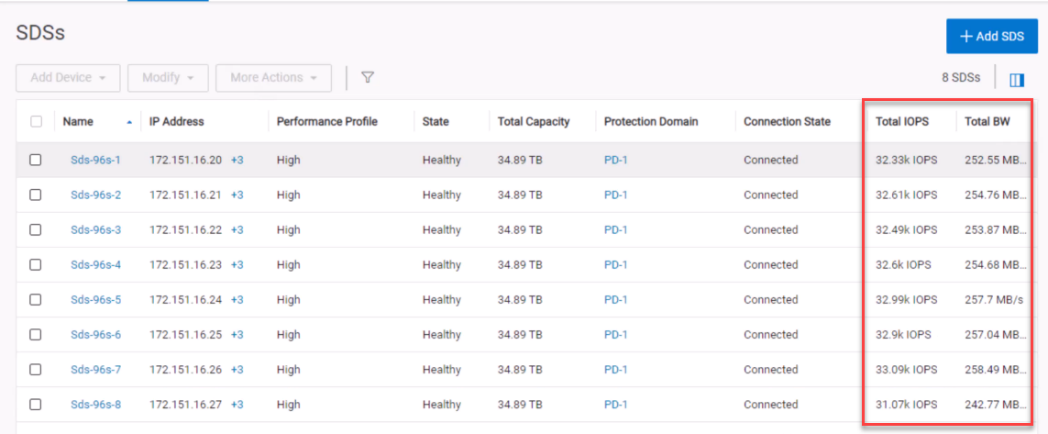
Figure 13. Balanced SDSs
An SDC will use every SDS over a client/server mesh, illustrated in Figure 14. The SDC has automatic multipathing to each of the SDSs, ensuring IOPs are balanced over the front end. This massively parallel architecture ensures maximum throughput while minimizing latency.
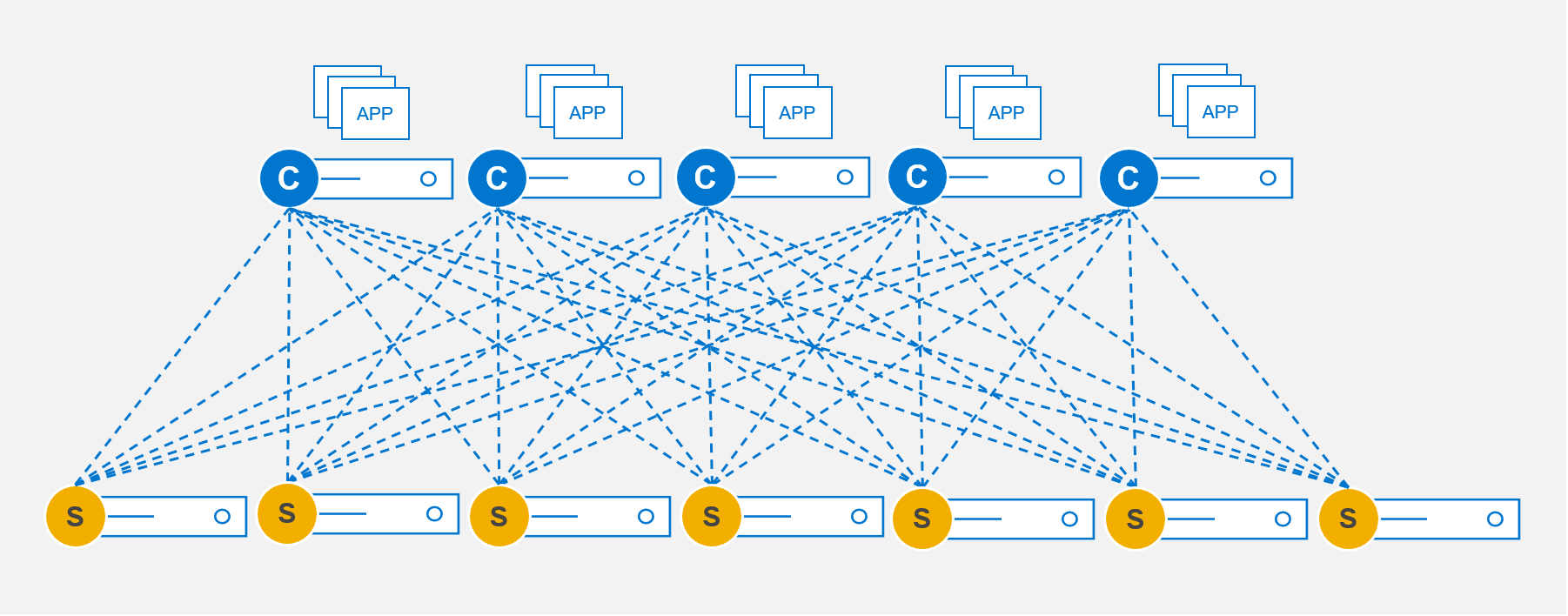
Figure 14. Client-Server mesh
Intelligent resiliency
The mesh technology in PowerFlex that gives it incredible performance is also the foundation of its outstanding resiliency. If a drive or node fails, the SDSs will use the same mechanism described in the previous section to rebalance and rebuild data, ensuring 6 9’s of availability[1]. PowerFlex can reprotect the data in seconds after a drive failure and in minutes after a node failure. The following figure elucidates how the rebuild duration improves with scale.
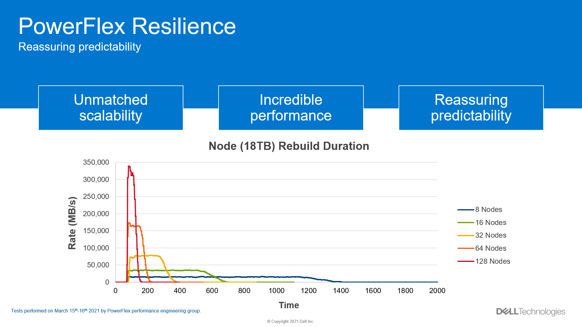
Figure 15. Rebuild duration
PowerFlex does not use any type of hardware disk-level RAID protection. Instead, on write operations, the SDC sends a chunk of data to an SDS (primary). The SDS then writes the data to a hard drive on the local node. The SDS also ships the chunk to a second SDS (secondary) node which then writes the data to a disk on that node.
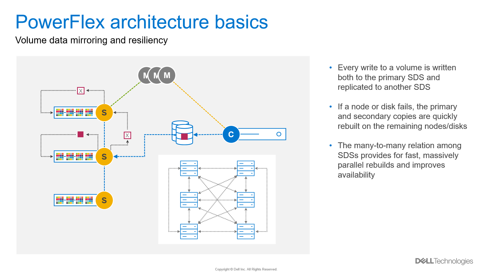
Figure 16. Data mirroring
What about planned outages for maintenance? PowerFlex gives administrators three maintenance mode options, each of which is nondisruptive.
The first is Node removal, which is a graceful removal of a single node. PowerFlex does a many-to-many rebalance of data among the remaining nodes during a node removal operation. Data is fully protected, and the PowerFlex system remains operational. The system capacity and performance potential will be reduced when the operation is initiated. This mode is typically used to permanently remove a node from the cluster.
Instant Maintenance Mode (IMM) is designed for quick entry and exit from the maintenance operation. IMM is ideal for rolling upgrades where the maintenance window is short. Data on the node is unavailable and not rebalanced to other nodes in the cluster when a node is placed in IMM. Applications accessing data during IMM are directed to other nodes containing the copy of data. Writes are tracked, and when the node exits IMM, the changes are written to the node in question.
The last mode is called Protected Maintenance Mode (PMM), which provides similar data availability to the other maintenance modes without the single copy exposure risk of IMM. As with the node removal operation, when a node is placed into PMM, PowerFlex will perform a many-to-many copy rebalance to the other nodes. Data on the node placed in PMM is unavailable upon entering and during PMM. Work cannot begin on the node until the copy is complete. Entering PMM takes longer to ensure the data on the node is copied to other storage nodes.
Like IMM writes affecting the node are tracked, and once the node exits PMM, the updates are written to the node. For more detailed information about PowerFlex maintenance modes, check out this white paper.
Management and orchestration
PowerFlex offers an extensive management and orchestration (M&O) ecosystem, starting with PowerFlex Manager. PowerFlex Manager is the unified management application for all PowerFlex consumption models, providing life cycle management, automation, and compliance of software and firmware for PowerFlex rack and appliance. PowerFlex Manager also automates life cycle management of core PowerFlex software for all consumption models.
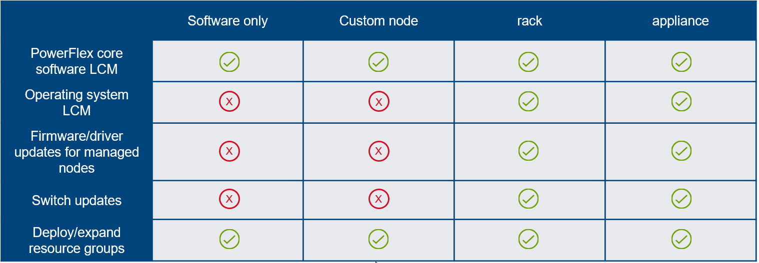
Figure 17. PowerFlex Manager LCM
In addition to life cycle management, PowerFlex Manager reports on the health, capacity, and performance of PowerFlex hardware components and software and is the ingress point for the full-featured PowerFlex REST API.
Dell Technologies offers automation tools for PowerFlex such as a Python SDK, Ansible modules, and a Terraform provider. Looking to place containerized workloads on PowerFlex? Dell Technologies provides a Container Storage Interface (CSI) driver and Container Storage Modules (CSM) for managing a Kubernetes infrastructure on PowerFlex. Want more information about this topic? Head over to GitHub.
Conclusion
I could continue about the PowerFlex DNA, but I think we can wrap up for now. Stay tuned for more to follow in a future blog. If you are looking for more information in the meantime, head over to Dell Technologies Info Hub where you will find great technical resources such as white papers, reference architectures, solution briefs, and videos.
Resources
Dell PowerFlex YouTube Channel
From Chaos to Order Unifying Silos infographic
Dell Technologies GitHub Repository
Dell PowerFlex: Maintenance Modes
Author: Roy Laverty, Principal Technical Marketing Engineer
LinkedIn: https://linkedin.com/in/roy-laverty
Twitter: @RoyLaverty
[1] Availability claims based on internal Dell testing. (Source: Dell PowerFlex - Unbounded software-defined infrastructure platform.)

VMware Explore, PowerFlex, and Silos of Glitter: this blog has it all!
Fri, 18 Aug 2023 19:30:20 -0000
|Read Time: 0 minutes
Those who know me are aware that I’ve been a big proponent of one platform that must be able to support multiple workloads—and Dell PowerFlex can. If you are at VMware Explore you can see a live demo of both traditional database workloads and AI workloads running on the same four PowerFlex nodes.
When virtualization took the enterprise by storm, a war was started against silos. First was servers, and the idea that we can consolidate them on a few large hosts with virtualization. This then rapidly moved to storage and continued to blast through every part of the data center. Yet today we still have silos. Mainly in the form of workloads, these hide in plain sight - disguised with other names like “departmental,” “project,” or “application group.”
Some of these workload silos are becoming even more stealthy and operate under the guise of needing “different” hardware or performance, so IT administrators allow them to operate in a separate silo.
That is wasteful! It wastes company resources, it wastes the opportunity to do more, and it wastes your time managing multiple environments. It has become even more of an issue with the rise of Machine Learning (ML) and AI workloads.
If you are at VMware Explore this year you can see how to break down these silos with Dell PowerFlex at the Kioxia booth (Booth 309). Experience the power of running ResNet 50 image classification and OLTP (Online Transactional Processing) workloads simultaneously, live from the show floor. And if that’s not enough, there are experts, and lots of them! You might even get the chance to visit with the WonderNerd.
This might not seem like a big deal, right? You just need a few specialty systems, some storage, and a bit of IT glitter… some of the systems run the databases, some run the ML workloads. Sprinkle some of that IT glitter and poof you’ve got your workloads running together. Well sort of. They’re in the same rack at least.
Remember: silos are bad. Instead, let’s put some PowerFlex in there! And put that glitter back in your pocket, this is a data center, not a five-year old’s birthday party.
PowerFlex supports NVIDIA GPUs with MIG technology which is part of NVIDIA AI Enterprise, so we can customize our GPU resources for the workloads that need them. (Yes, there is nothing that says you can’t run different workloads on the same hosts.) Plus, PowerFlex uses Kioxia PM7 series SSDs, so there is plenty of IOPS to go around while ensuring sub-millisecond latency for both workloads. This allows the data to be closer to the processing, maybe even on the same host.
In our lab tests, we could push one million transactions per minute (TPM) with OLTP workloads while also processing 6620 images per second using a RESNET50 model built on NVIDIA NGC containers. These are important if you want to keep customers happy, especially as more and more organizations add AI/ML capabilities to their online apps, and more and more data is generated from all those new apps.
Here are the TPM results from the demo environment that is running our four SQL VMs. The TPMs in this test are maxing out around 320k and the latency is always sub-millisecond. This is the stuff you want to show off, not that pocket full of glitter.
Yeah, you can silo your environments and hide them with terms like “project” and “application group,” but everyone will still know they are silos.
We all started battling silos at the dawn of virtualization. PowerFlex with Kioxia drives and NVIDIA GPUs gives administrators a fighting chance to win the silo war.
You can visit the NVIDIA team at Lounge L3 on the show floor during VMware Explore. And of course, you have to stop by the Kioxia booth (309) to see what PowerFlex can do for your IT battles. We’ll see you there!
Author: Tony Foster
Twitter: | |
LinkedIn: | |
Personal Blog: | |
Location: | The Land of Oz [-6 GMT] |
Contributors: Kailas Goliwadekar, Anup Bharti

Managing Dell PowerFlex Licensing and Being Way Less Sad
Mon, 24 Jul 2023 21:20:14 -0000
|Read Time: 0 minutes
Imagine there was an easy way to view and manage your Dell PowerFlex licenses. Wouldn’t that be nice? I know I’d be way less sad. Well guess what, I’m way less sad, and there’s a way to easily manage your PowerFlex licenses.
I was on a call today with one of our product managers. He was showing something really cool, and I just had to share it with everyone. You can go into CloudIQ and view all your PowerFlex licenses.
You might think, “big deal, licenses.” You’re right! It is a big deal. Okay, a moderate sized deal, it makes me less sad. And here’s why. Have you ever had to track licenses for your environment in a spreadsheet? How about sharing that spreadsheet with everyone else on your team and hoping that no one accidently removes too many rows or types in the wrong cell. Or maybe you have to correlate a license to how much capacity you’re using. I’m sure 90% of users love this method. What’s that I hear you yelling at your monitor, I’m wrong???
You’re correct, hardly anyone wants to track licenses that way. Why? Because its error prone and difficult to manage, plus it’s not automated. Oh, and it’s licensing. Well, CloudIQ can help you address a lot of this, at least for your PowerFlex environment.
That’s right. You log in, click on the Entitlements and System Licenses option in the menu, and you can see all your entitlements for PowerFlex. With that you can see how many terabytes of capacity each license has as well as the start and end dates. It’s all there, no spreadsheets, no manual entry, it’s easy to manage. Maybe 90% of users would prefer this method over a spreadsheet. You can see this functionality in the screenshot below.
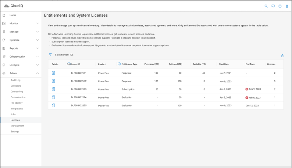
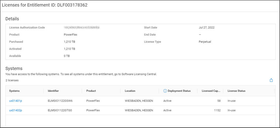
It gets better though…. Maybe you want to dig into the details of your environment and see how different licenses are being used. Maybe you are licensed for a petabyte of storage but you’re missing 50ish terabytes and want to see where they went. If you click on the details of an entitlement, you can see which systems are consuming capacity from the license. This makes it a lot easier than a spreadsheet to track down. You can see this in the following screenshot.
I’m sure it’s hard to get excited over licensing, but hopefully this makes you way less sad knowing you don’t have to try and track all this in a spreadsheet. Instead, you just log in to CloudIQ, then click on Entitlements and System Licenses. Poof, there it all is, in an easy-to-consume format. And for those who still want to manage their licenses in a spreadsheet, there’s an export option at the top of the table just for you. You can create pivot tables to your heart’s content. For everyone else, you’ve just unlocked a PowerFlex secret. Hopefully, like me, this makes you way less sad about licensing.
If you’re interested in finding out more about what you can do with licensing in CloudIQ, reach out to your Dell representative, who can guide you on all CloudIQ has to offer.
Author: Tony Foster
Sr. Principal Technical Marketing Engineer
Twitter: | |
LinkedIn: | |
Personal Blog: | |
Location: | The Land of Oz [-6 GMT] |

Can I do that AI thing on Dell PowerFlex?
Thu, 20 Jul 2023 21:08:09 -0000
|Read Time: 0 minutes
The simple answer is Yes, you can do that AI thing with Dell PowerFlex. For those who might have been busy with other things, AI stands for Artificial Intelligence and is based on trained models that allow a computer to “think” in ways machines haven’t been able to do in the past. These trained models (neural networks) are essentially a long set of IF statements (layers) stacked on one another, and each IF has a ‘weight’. Once something has worked through a neural network, the weights provide a probability about the object. So, the AI system can be 95% sure that it’s looking at a bowl of soup or a major sporting event. That, at least, is my overly simplified description of how AI works. The term carries a lot of baggage as it’s been around for more than 70 years, and the definition has changed from time to time. (See The History of Artificial Intelligence.)
Most recently, AI has been made famous by large language models (LLMs) for conversational AI applications like ChatGPT. Though these applications have stoked fears that AI will take over the world and destroy humanity, that has yet to be seen. Computers still can do only what we humans tell them to do, even LLMs, and that means if something goes wrong, we their creators are ultimately to blame. (See ‘Godfather of AI’ leaves Google, warns of tech’s dangers.)
The reality is that most organizations aren’t building world destroying LLMs, they are building systems to ensure that every pizza made in their factory has exactly 12 slices of pepperoni evenly distributed on top of the pizza. Or maybe they are looking at loss prevention, or better traffic light timing, or they just want a better technical support phone menu. All of these are uses for AI and each one is constructed differently (they use different types of neural networks).
We won’t delve into these use cases in this blog because we need to start with the underlying infrastructure that makes all those ideas “AI possibilities.” We are going to start with the infrastructure and what many now consider a basic (by today’s standards) image classifier known as ResNet-50 v1.5. (See ResNet-50: The Basics and a Quick Tutorial.)
That’s also what the PowerFlex Solution Engineering team did in the validated design they recently published. This design details the use of ResNet-50 v1.5 in a VMware vSphere environment using NVIDIA AI Enterprise as part of PowerFlex environment. They started out with the basics of how a virtualized NVIDIA GPU works well in a PowerFlex environment. That’s what we’ll explore in this blog – getting started with AI workloads, and not how you build the next AI supercomputer (though you could do that with PowerFlex as well).
In this validated design, they use the NVIDIA A100 (PCIe) GPU and virtualized it in VMware vSphere as a virtual GPU or vGPU. With the infrastructure in place, they built Linux VMs that will contain the ResNet-50 v1.5 workload and vGPUs. Beyond just working with traditional vGPUs that many may be familiar with, they also worked with NVIDIA’s Multi-Instance GPU (MIG) technology.
NVIDIA’s MIG technology allows administrators to partition a GPU into a maximum of seven GPU instances. Being able to do this provides greater control of GPU resources, ensuring that large and small workloads get the appropriate amount of GPU resources they need without wasting any.
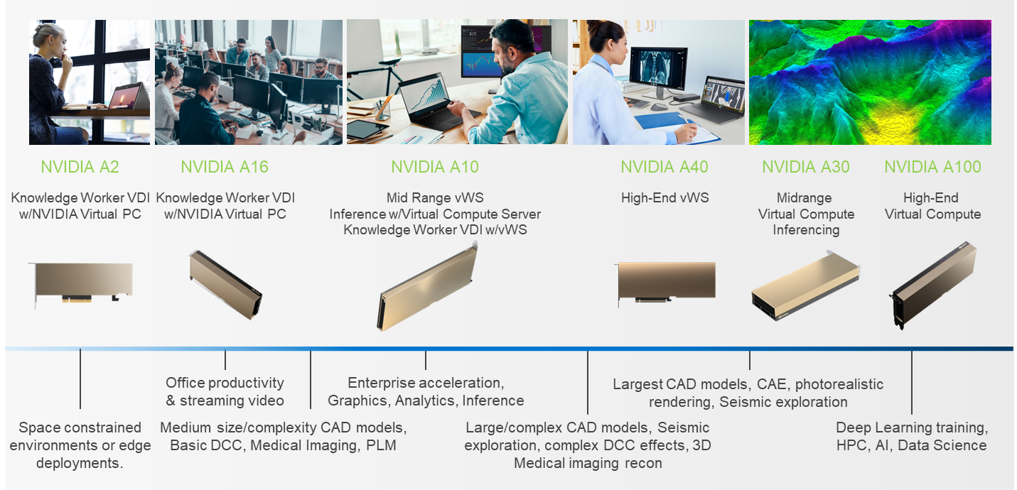
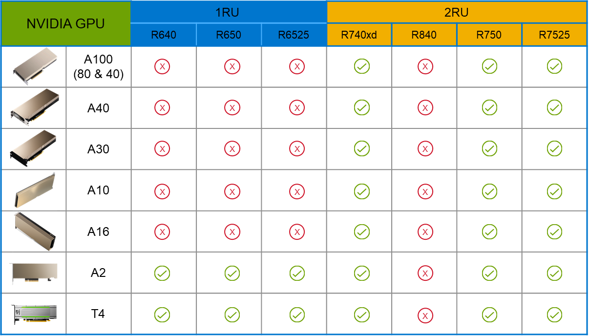
PowerFlex supports a large range of NVIDIA GPUs for workloads, from VDI (Virtual Desktops) to high end virtual compute workloads like AI. You can see this in the following diagram where there are solutions for “space constrained” and “edge” environments, all the way to GPUs used for large inferencing models. In the table below the diagram, you can see which GPUs are supported in each type of PowerFlex node. This provides a tremendous amount of flexibility depending on your workloads.
The validated design describes the steps to configure the architecture and provides detailed links to the NVIDIAand VMware documentation for configuring the vGPUs, and the licensing process for NVIDIA AI Enterprise.
These are key steps when building an AI environment. I know from my experience working with various organizations, and from teaching, that many are not used to working with vGPUs in Linux. This is slowly changing in the industry. If you haven’t spent a lot of time working with vGPUs in Linux, be sure to pay attention to the details provided in the guide. It is important and can make a big difference in your performance.
The following diagram shows the validated design’s logical architecture. At the top of the diagram, you can see four Ubuntu 22.04 Linux VMs with the NVIDIA vGPU driver loaded in them. They are running on PowerFlex hosts with VMware ESXi deployed. Each VM contains one NVIDIA A100 GPU configured for MIG operations. This configuration leverages a two-tier architecture where storage is provided by separate PowerFlex software defined storage (SDS) nodes.
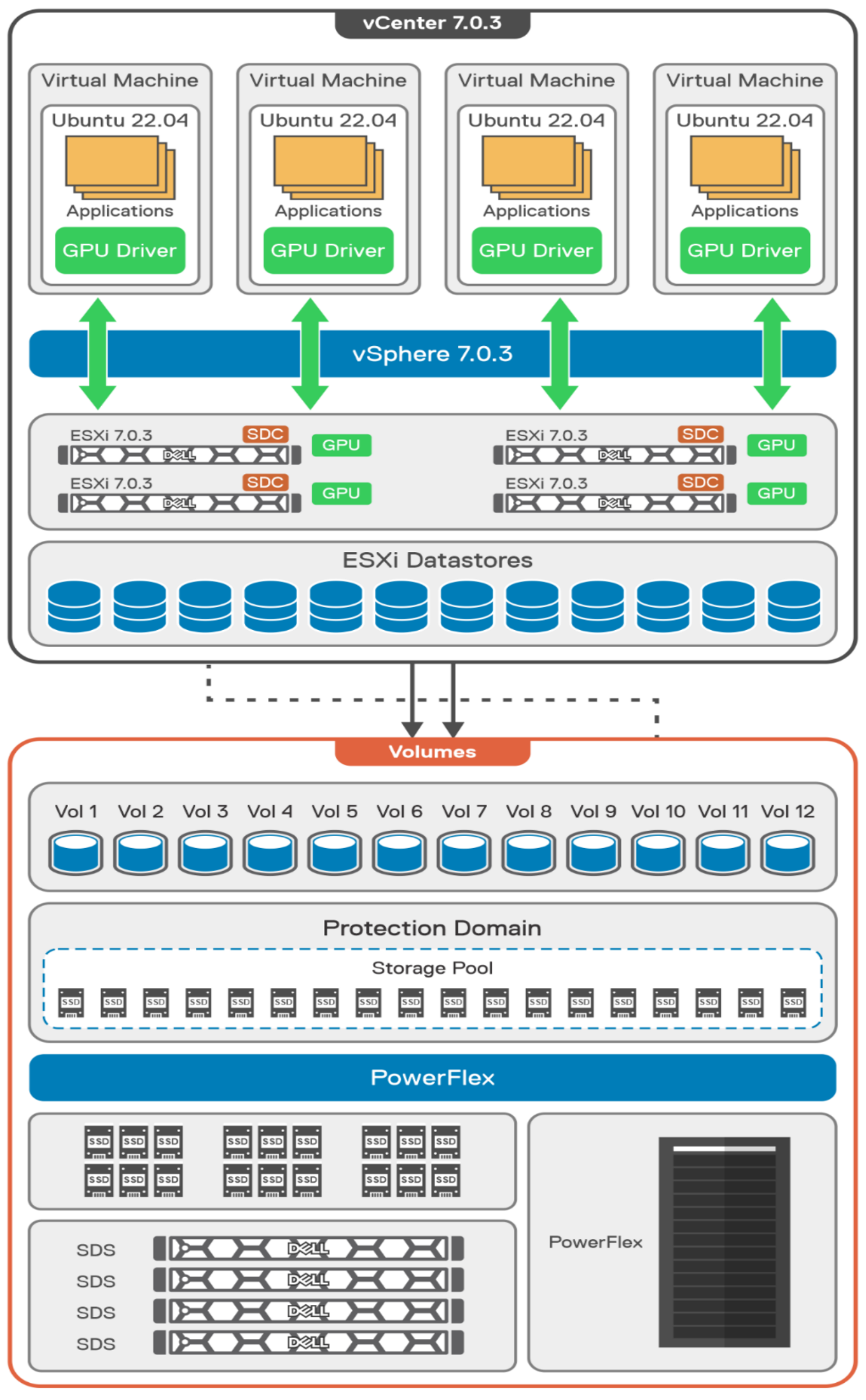
A design like this allows for independent scalability for your workloads. What I mean by this is during the training phase of a model, significant storage may be required for the training data, but once the model clears validation and goes into production, storage requirements may be drastically different. With PowerFlex you have the flexibility to deliver the storage capacity and performance you need at each stage.
This brings us to testing the environment. Again, for this paper, the engineering team validated it using ResNet-50 v1.5 using the ImageNet 1K data set. For this validation they enabled several ResNet-50 v1.5 TensorFlow features. These include Multi-GPU training with Horovod, NVIDIA DALI, and Automatic Mixed Precision (AMP). These help to enable various capabilities in the ResNet-50 v1.5 model that are present in the environment. The paper then describes how to set up and configure ResNet-50 v1.5, the features mentioned above, and details about downloading the ImageNet data.
At this stage they were able to train the ResNet-50 v1.5 deployment. The first iteration of training used the NVIDIA A100-7-40C vGPU profile. They then repeated testing with the A100-4-20C vGPU profile and the A100-3-20C vGPU profile. You might be wondering about the A100-2-10C vGPU profile and the A100-1-5C profile. Although those vGPU profiles are available, they are more suited for inferencing, so they were not tested.
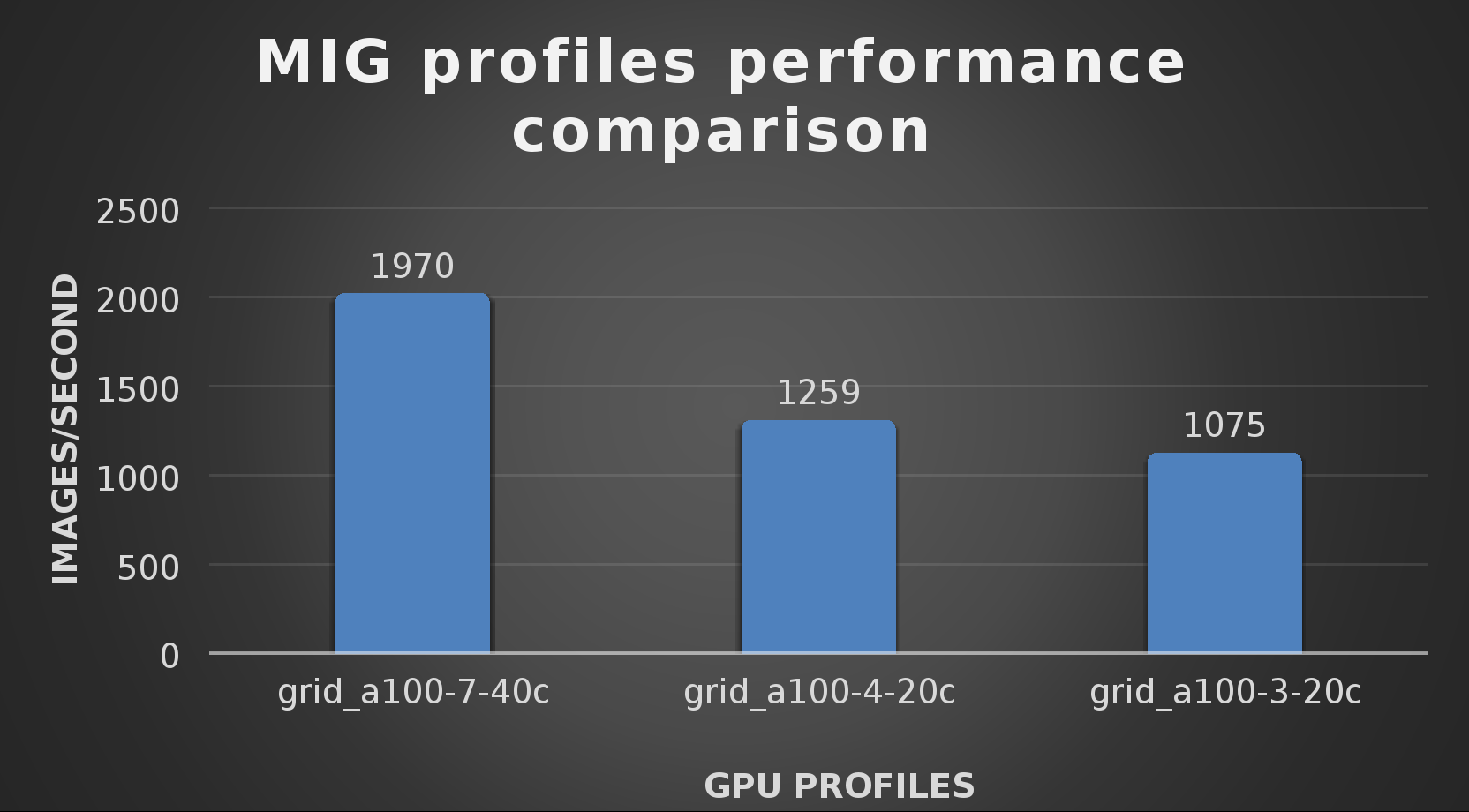
The results from validating the training workloads for each vGPU profile is shown in the following graph. The vGPUs were running near 98% capacity according to nvitop during each test. The CPU utilization was 14% and there was no bottle neck with the storage during the tests.
With the models trained, the guide then looks at how well inference runs on the MIG profiles. The following graph shows inferencing images per second of the various MIG profiles with ResNet-50 v1.5.
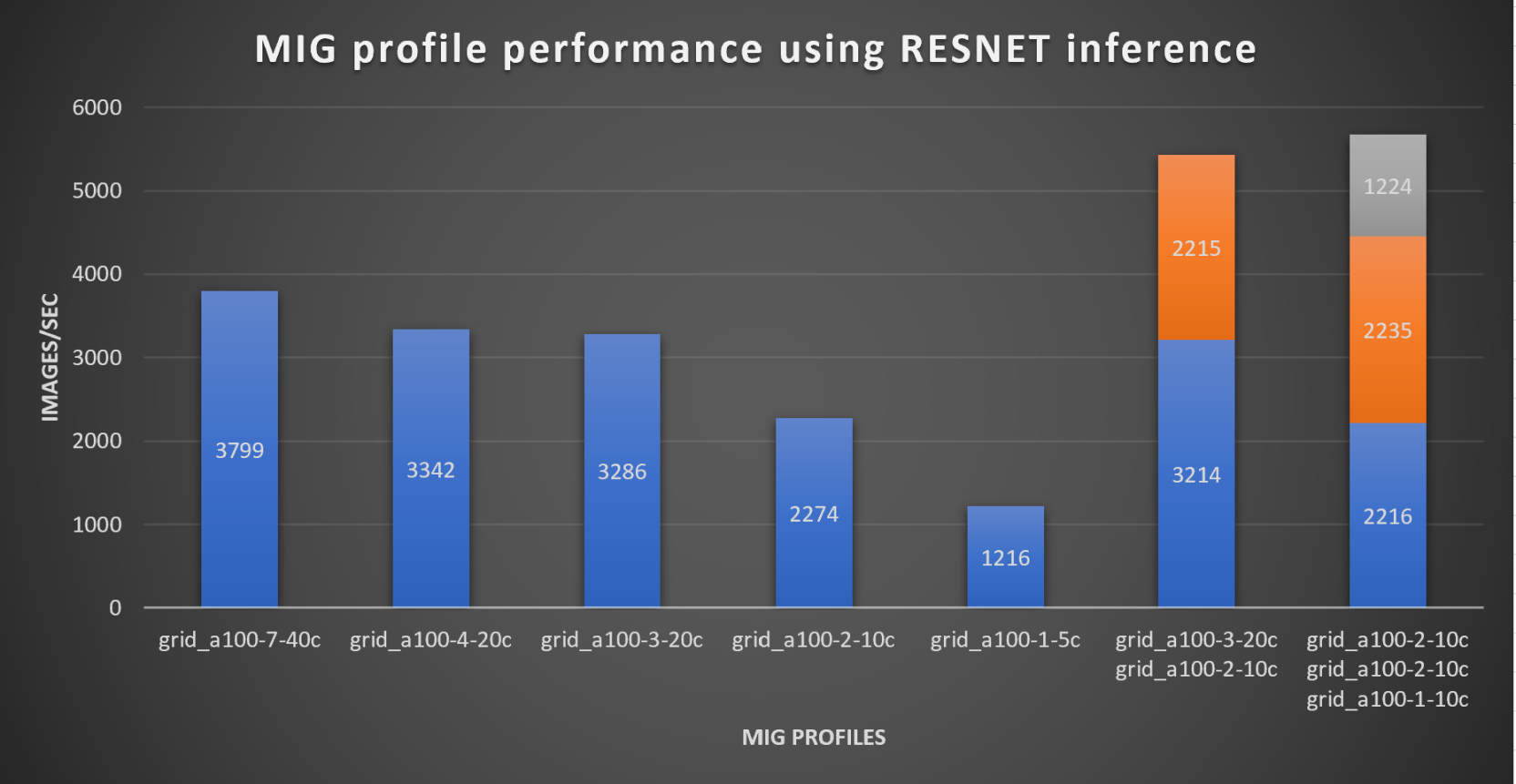
It’s worth noting that the last two columns show the inferencing running across multiple VMs, on the same ESXi host, that are leveraging MIG profiles. This also shows that GPU resources are partitioned with MIG and that resources can be precisely controlled, allowing multiple types of jobs to run on the same GPU without impacting other running jobs.
This opens the opportunity for organizations to align consumption of vGPU resources in virtual environments. Said a different way, it allows IT to provide “show back” of infrastructure usage in the organization. So if a department only needs an inferencing vGPU profile, that’s what they get, no more, no less.
It’s also worth noting that the results from the vGPU utilization were at 88% and CPU utilization was 11% during the inference testing.
These validations show that a Dell PowerFlex environment can support the foundational components of modern-day AI. It also shows the value of NVIDIA’s MIG technology to organizations of all sizes: allowing them to gain operational efficiencies in the data center and enable access to AI.
Which again answers the question of this blog, can I do that AI thing on Dell PowerFlex… Yes you can run that AI thing! If you would like to find out more about how to run your AI thing on PowerFlex, be sure to reach out to your Dell representative.
Resources
- The History of Artificial Intelligence
- ‘Godfather of AI’ leaves Google, warns of tech’s dangers
- ResNet-50: The Basics and a Quick Tutorial
- Dell Validated Design for Virtual GPU with VMware and NVIDIA on PowerFlex
- NVIDIA NGC Catalog ResNet v1.5 for PyTorch
- NVIDIA AI Enterprise
- NVIDIA A100 (PCIe) GPU
- NVIDIA Virtual GPU Software Documentation
- NVIDIA A100-7-40C vGPU profile
- NVIDIA Multi-Instance GPU (MIG)
- NVIDIA Multi-Instance GPU User Guide
- Horovod
- ImageNet
- DALI
- Automatic Mixed Precision (AMP)
- nvitop
Author: Tony Foster
Sr. Principal Technical Marketing Engineer
Twitter: | |
LinkedIn: | |
Personal Blog: | |
Location: | The Land of Oz [-6 GMT] |

What to do with all that data? Answer: SingleStore on PowerFlex
Wed, 10 May 2023 22:55:28 -0000
|Read Time: 0 minutes
Every organization has data, every organization has databases, every organization must figure out what to do with all that data from those databases. According to research by the University of Tennessee, Knoxville’s Haslam College of Business there were 44 zettabytes of data in 2020, and by 2025 it is estimated that 463 exabytes of data will be created daily. That’s a lot of data, and even if your organization only contributes a fraction of a precent to those 463 exabytes of data a day, that’s still a lot of data to manage. A great approach to this modern ocean of data is using SingleStore on Dell PowerFlex.
Recently Dell and SingleStore released a joint validation white paper on a virtualized SingleStore environment running on PowerFlex. The paper provides an overview of the technologies used and then looks at an architecture that can be used to run SingleStore on PowerFlex. After that, the paper looks at how the environment was validated.
SingleStore
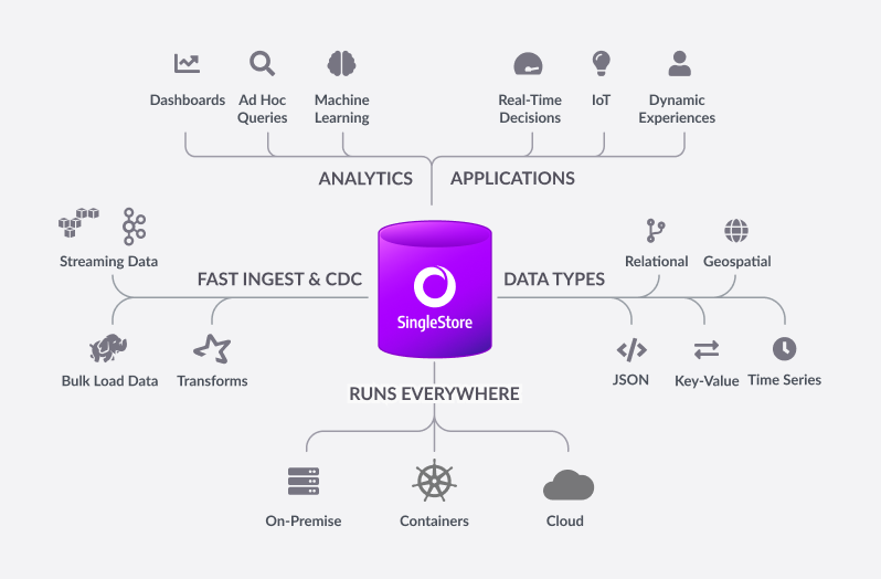
Before I get into the details of the paper, I suspect there might be a few readers who have yet to hear about SingleStore or know about some of its great features, so let’s start there. Built for developers and architects, SingleStoreDB is based on a distributed SQL architecture, delivering 10–100 millisecond performance on complex queries—all while ensuring that your organization can effortlessly scale. Now let’s go a bit deeper….
The SingleStoreDB :
- Scales horizontally providing high throughput across a wide range of platforms.
- Maintains a broad compatibility with common technologies in the modern data processing ecosystem (for example, orchestration platforms, developer IDEs, and BI tools), so you can easily integrate it in your existing environment.
- Features an in-memory rowstore and an on-disk columnstore to handle both highly concurrent operational and analytical workloads.
- Features the SingleStore Pipelines data ingestion technology that streams large amounts of data at high throughput into the database with exactly once semantics.
This means that you can continue to run your traditional SQL queries against your every growing data, which all resides on a distributed system, and you can do it fast. This is a big win for organizations who have active data growth in their environment.
What makes this even better is the ability of PowerFlex to scale from a few nodes to thousands. This provides a few different options to match your growing needs. You can start with just your SingleStore system deployed on PowerFlex and migrate other workloads on to the PowerFlex environment as time permits. This allows you to focus on just your database environment to start and then, as infrastructure comes up for renewal, you migrate those workloads and scale up your environment with more compute and storage capacity.
Or maybe you are making a bigger contribution to that 463 exabytes of data per day I mentioned earlier, and you need to scale out your environment to handle your data’s growth. You can do that too!
That’s the great thing about PowerFlex, you can consume resources independently of each other. You can add more storage or compute as you need them.
Additionally, with PowerFlex, you can deliver bare-metal and virtualized environments without having to choose only one. That’s right—you can run bare-metal servers right next to virtualized workloads.
Architecture
The way the engineers built this environment was using PowerFlex deployed in a hyper-converged infrastructure (HCI) configuration where the compute nodes are also storage nodes. (PowerFlex supports both two-tier architectures and HCI.)
As shown in the following diagram, our engineering team used five Dell PowerEdge R640 servers with dual CPUs, 384 GB of RAM, and eight SSDs per node. These five nodes were configured as HCI nodes and connected with a 25 Gbps network. The storage from across the nodes is aggregated to create a large software-defined pool of storage as a single protection domain that provides volumes to the SingleStore VMs. This is ideal for even the most demanding databases due to its high I/O capability.
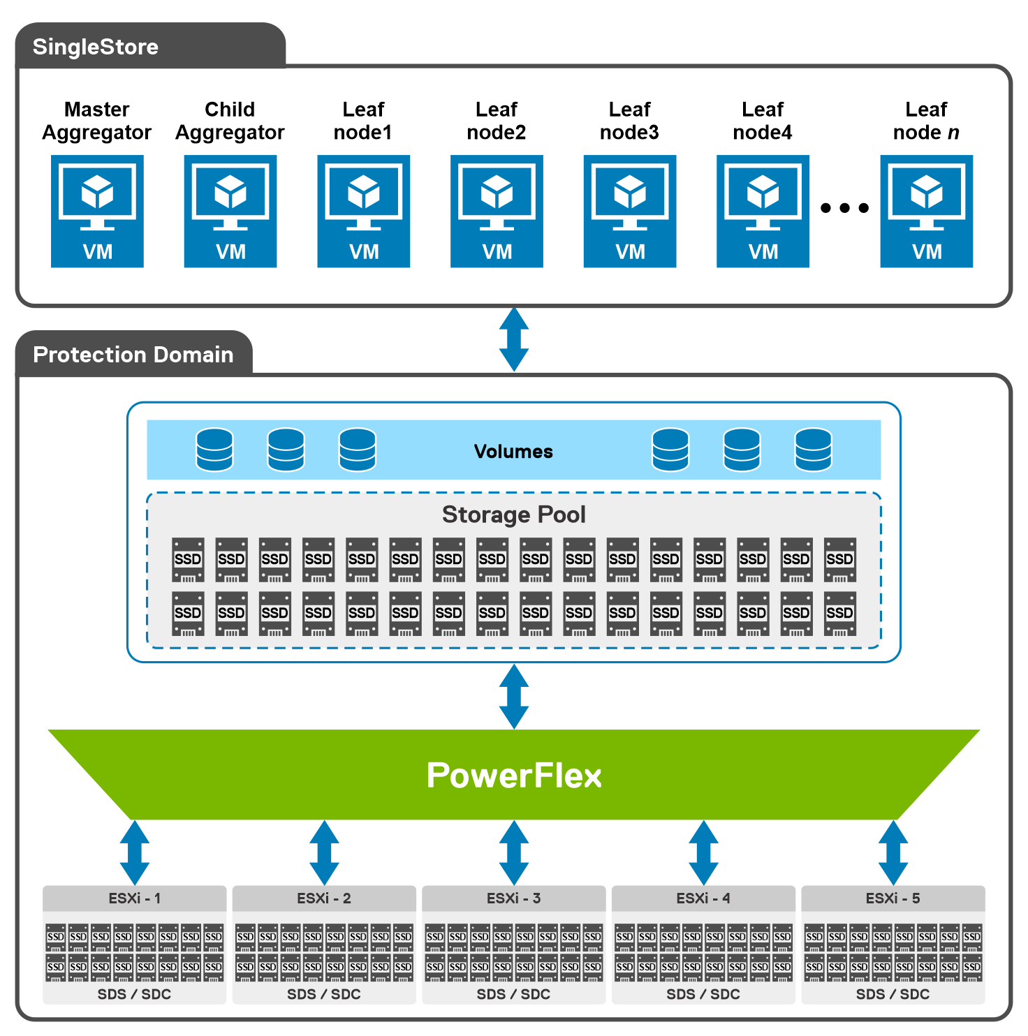
For this validation, the SingleStore Cluster VMs consist of two aggregator VMs and multiple leaf VMs. The white paper details the configuration of these VMs.
Additionally, the white paper provides an overview of the steps used to deploy SingleStore on VMware vSphere in a PowerFlex environment. For this validation, they followed the online user interface method to deploy SingleStore.
Testing
With the environment configured, the white paper then discusses how to validate the environment using TPC-DS. This tool provides 99 different queries that can be used to test a database. For this validation, only 95 of the 99 were used. The paper then describes both how the sample data set was created and how the tests were run.
The validation tests were run on 4, 6, and 8 leaf node configurations. This was done to understand the variation in performance as the environment scales. The testing showed that having more SingleStore leaf nodes results in better performance outcomes.
The testing also showed that there were no storage bottlenecks for the TPC-DS like workload and that using more powerful CPUs could further enhance the environment.
The white paper shows how SingleStore and PowerFlex can be used to create a dynamic and robust environment for your growing data needs as you do your part to contribute to the 463 exabytes of data that is expected to be created daily by 2025. To find out more about this design, contact your Dell representative.
Resources
Author: Tony Foster
Twitter: @wonder_nerd
LinkedIn

What’s New in PowerFlex 4.0 REST API?
Mon, 08 May 2023 18:14:08 -0000
|Read Time: 0 minutes
Wow, it’s been a busy year for PowerFlex! It started with the major announcement of PowerFlex on AWS at Dell Technologies World 2022. Then, in late summer of 2022 we announced a major update in PowerFlex v4.0. PowerFlex v4.0 added NVMe/TCP support, File Storage services, and a new management & operations (M&O) stack called unified PowerFlex Manager. In September of 2022 the PowerFlex Solutions team released the Dell Validated Platform for Red Had OpenShift on PowerFlex.
Many of the enhancements solidify PowerFlex’s position as the ultimate infrastructure platform. One such improvement is with the REST API which is the topic of this blog. If you are new to REST API and are looking for a quick introduction, I suggest you start by reading the blog Getting Started with REST API by Florian and Parasar. With that base of understanding, let’s take a closer look at the improvements made to REST API in PowerFlex 4.0.
Single endpoint
The improvements made to the REST API that I cover here are part of the new unified PowerFlex Manager application. The following figure shows the PowerFlex management plane prior to PowerFlex 4.0. As you can see, the management plane differs by the consumption model. Here there are two REST API endpoints: the PowerFlex Gateway endpoint and the PowerFlex Manager endpoint.
Figure 1. The PowerFlex Management Plane before 4.0
The PowerFlex Gateway endpoint provides access to block management and installation manager functions for all consumption models. The PowerFlex Manager endpoint provides access to lifecycle management functions for rack and appliance consumption models.
By contrast, PowerFlex Manager 4.0 simplifies things a bit by unifying the management applications into a single management and operation (M&O) stack (Figure 2). Want to know more about the new unified PowerFlex Manager? Check out the blog An Introduction to the Unified PowerFlex Manager Platform by Simon Stevens and Tony Foster. By unifying the management stacks, we have consolidated the two REST API endpoints into a single endpoint hosted by the unified PowerFlex Manager application.
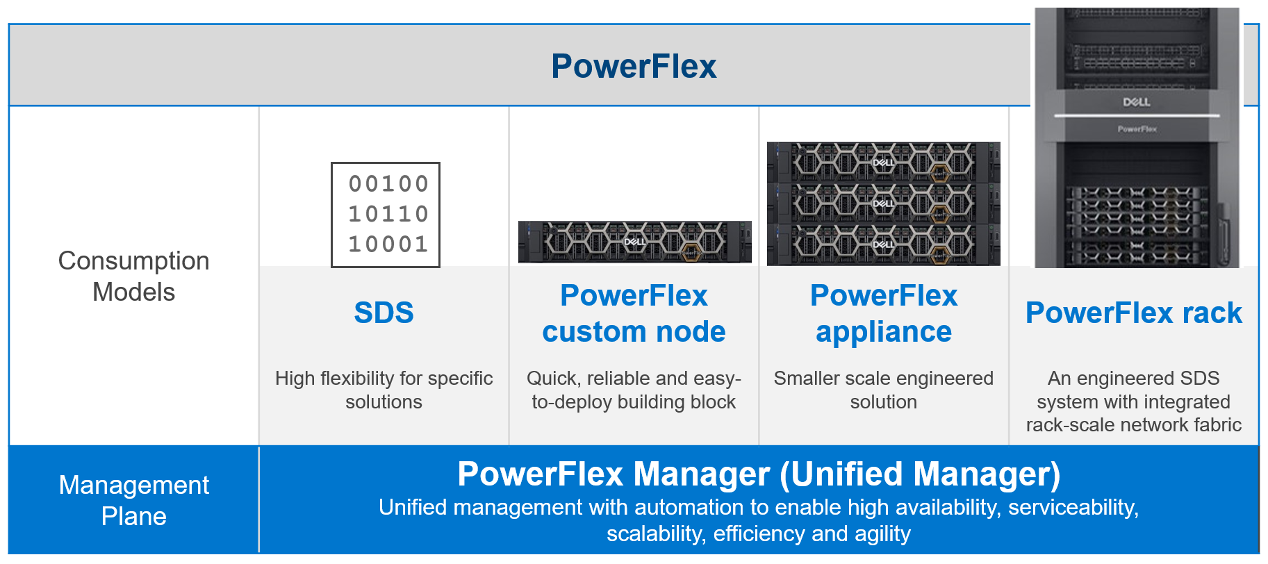
Figure 2. PowerFlex Management Plane 4.0
Single Authentication Method
The single endpoint allows the implementation of a single, and more secure, authentication method. The unified PowerFlex Manager uses the OAuth 2.0 industry standard for authorization. To authenticate, a user passes their username and password to PowerFlex Manager. The ingress microservice on PowerFlex Manager forwards the request to the authentication microservice.
Here’s an example of authentication with PowerFlex Manager v4.0:
curl --location --request POST 'https://<pfxm>/rest/auth/login' --header 'Content-Type: application/json' --data-raw '{"username": "admin", "password": "Password1234"}'When a user session has been authenticated, they receive a bearer token in the response body. The bearer token can then be used with subsequent API calls as part of the authorization header.
Here’s an example of an authentication response, where access_token is the Bearer token used in subsequent API calls:
{
    "scope": "openid profile email",
     "access_token": "eyJhb…_sHfNdkA9jTPgj_cOd-_lrlT_of2H7Nni9Yn-g",
    "expires_in": 300,
    "refresh_expires_in": 1800,
     "refresh_token": "eyJhb…J5uI_f1fkpB7vjatgc3Z3QQm1w8tFhSSkLVT4",
    "token_type": "Bearer",
    "id_token": "eyJhbGciO…ZoomRlk9ueJggFWCsC7BuNTKwhnCnNDRzzAUiw",
     "session_state": "d609babf-463d-4e49-84c3-e73360a90500"
}
And here’s an example of passing the bearer token in a call to /rest/v1/alerts:
curl --location 'https://<pfmp>/rest/v1/alerts' --header 'Accept: application/json' --header 'Content-Type: application/json'--header 'Authorization: Bearer eyJhb…_sHfNdkA9jTPgj_cOd-_lrlT_of2H7Nni9Yn-g '
In earlier releases of PowerFlex, the REST API server on the PowerFlex Gateway used basic authentication, and the REST API server on the PowerFlex Manager used a custom authentication scheme. Having a single authentication scheme and endpoint simplifies the life of a PowerFlex administrator. The greater benefit, of course, is that OAuth 2.0 is a modern authorization protocol with the benefits of being an open standard.
Dell Technologies PowerAPI
Another enhancement is the adoption of the Dell Technologies PowerAPI style, which is compliant with the OpenAPI Specification (OAS) v3.0. This is the first phase of adopting the PowerAPI style and includes the features specified in the table below.
Feature | Description |
Authentication | Login, logout, & refresh token |
SSO | Manage users |
NAS | Manage PowerFlex file storage objects |
Alerts | Manage alerts and alert templates |
Events | Manage events |
Notifier | Manage external source and destinations, policies, and SMTP services |
Rest assured that the legacy REST API features from the PowerFlex Gateway and PowerFlex Manager remain unchanged in PowerFlex 4.0. The legacy APIs include PowerFlex Block API, PowerFlex Installation Manager API, and the PowerFlex Manager API. All will remain in place until they are fully integrated with the PowerAPI.
API | Description |
PowerFlex Block | Manage block storage, snapshots, and replication |
PowerFlex Manager | Compliance of rack and appliance |
PowerFlex Installer | PowerFlex Installation Manager/Gateway |
PowerAPI | Authentication, SSO, users, NAS, events, and alerts |
This is just a high-level introduction regarding improvements made in PowerFlex REST API 4.0. If you are looking for a deeper dive and some use case examples, check out my white paper listed in the resources section below. I have also included links to the Info Hub DevOps section and the PowerFlex REST API documentation on the Dell Technologies Developer portal.
To find out more about PowerFlex, contact your Dell representative.
Resources
Author: Roy Laverty, Principal Technical Marketing Engineer
Twitter: @RoyLaverty

Amazon EKS Connector with EKS Anywhere on Dell PowerFlex
Tue, 17 Jan 2023 06:19:04 -0000
|Read Time: 0 minutes
Why Amazon EKS Anywhere?
Digital transformation and application modernization have taken to new heights in the recent past. As businesses transform digitally, a demand for adopting modern infrastructure has equally grown to run applications at scale and provide fault-tolerant infrastructure.
With an ever-evolving technology landscape, it becomes important for industries to be well-positioned and equipped with the tools and capabilities to scale as the business grows.
Kubernetes is an effective containerization platform when it comes to running microservices and modern applications. Kubernetes is available with every major cloud provider as a service and can also be deployed in private cloud environments.
Amazon Elastic Kubernetes Service (EKS) Anywhere has taken the containerized platform to new heights. Amazon EKS Anywhere allows organizations to run an Amazon EKS cluster anywhere including in an on-premises private cloud.
What is Amazon EKS Connector?
In this blog, we will discuss the Amazon EKS connector that enables you to leverage Amazon EKS Console to view the entire Kubernetes infrastructure from a single pane of glass. Amazon EKS Anywhere and Amazon EKS Connector are strategically the best fit for businesses embracing hybrid cloud environments and private infrastructure setups.
Amazon EKS Connector is a new capability that allows administrators to securely connect any Kubernetes cluster (not limited to EKS Anywhere) to the EKS Console and provides a unified view of the entire Kubernetes environment.
Connecting your on-premises Kubernetes cluster with the EKS Console requires you to register the cluster with EKS and run the EKS Connector agent on the external Kubernetes cluster. EKS Connector agent installed on the connected cluster establishes a secured communication channel using a session manager.
There are multiple ways to register a Kubernetes cluster running anywhere with the AWS EKS console. You can use AWS CLI, eksctl, SDK or console. When registering with the eksctl or console option, a YAML manifest file is auto-populated with the required parameters and settings. However, some additional manual steps are required.
Note: Registering the Kubernetes cluster with the EKS console requires that you create the following IAM roles and groups in AWS IAM to be able to perform the required operations:
- Service-linked role for Amazon EKS
- EKS-Connector-Agent Role
Once the connection process is complete, administrators can use the Amazon EKS Console to view all connected clusters and their associated resources.
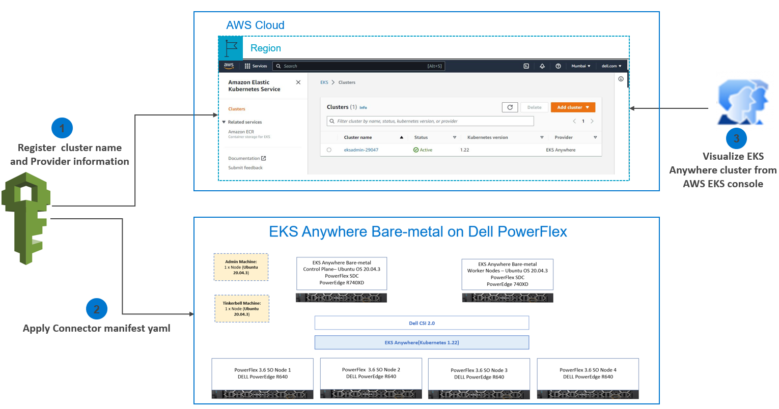 Amazon EKS Connector
Connecting a Kubernetes Cluster running on the Dell PowerFlex cluster to the EKS Console
Let us dig a little deeper into connecting a Kubernetes Cluster running on the Dell PowerFlex cluster to the EKS Console.
The cluster registration process involves two steps:
1. Register the cluster with Amazon EKS
2. Apply a connector YAML manifest file in the target cluster to enable connectivity.
Step 1: Register the cluster with Amazon EKS
EKS console includes a register option along with the create cluster option. Open the EKS console and go to the Clusters section. From Add cluster select the Register option as shown in the following image:
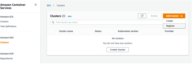 Registering the EKS Connector
- Enter the following details in the cluster registration form:
- Define a name for your cluster.
- Select the provider as EKS Anywhere (which is the case in this example).
- Select the EKS Connector Role that you created to enable the Kubernetes control plane to create resources on your behalf.
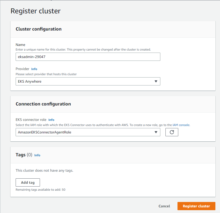 Cluster registration
- Click Register cluster.
- After the cluster is added the Cluster name is displayed and the status shows Active as shown in the following figure:
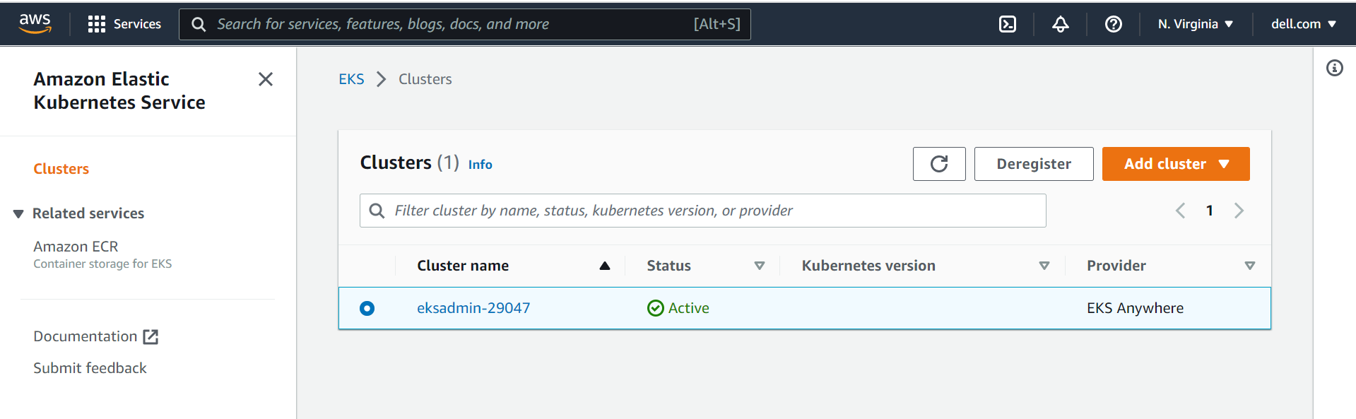 Cluster status
Step 2: Apply a connector YAML manifest file in the target cluster to enable connectivity
- After registering the cluster, you will be redirected to the Cluster Overview page. Click Download YAML file and install the file on your Kubernetes cluster to connect to the EKS console as shown in the following figure:
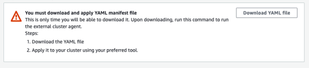 Cluster overview
- Apply downloaded eks-connector.yaml as follows:
kubectl apply -f eks-connector.yaml |
The EKS Connector runs in StatefulSet mode on your Kubernetes cluster. The connector establishes a connection and proxies the communication between the API server of your EKS Anywhere cluster and Amazon Web Services. The connector is used to display cluster data in the Amazon EKS console until you disconnect the cluster from AWS.
The YAML manifest file generated during the cluster registration process creates the following containers:
InitContainer: This container registers the EKS Connector agent with the Systems Manager control plane service and populates the registration information in the Kubernetes backend data store. InitContainer mounts this data to the EKS Connector agent’s volume when it is recycled. This eliminates the need of registration whenever a pod is recycled.
EKS Connector agent: This is an agent based on the SSM agent, running in container mode. This agent creates an outbound connection from the Kubernetes cluster to the AWS network. All subsequent requests from AWS are performed using the connection channels established by the EKS Connector agent.
Connector proxy: This agent acts as a proxy between the EKS Connector agent and Kubernetes API Server. This proxy agent uses the Kubernetes service account to impersonate the IAM user that accesses the console and fetches information from the Kubernetes API Server.
As one can see the EKS connector agent liaisons with the SSM service, which in turn interacts with the EKS service via EventBridge. To facilitate the interaction, the EKS connector agent role is required with appropriate permissions to create, open, and control the SSM channels. In the absence, of this important IAM role at AWS end, the creation and control of Systems Manager channels would not be possible eventually leading to an unsuccessful registration
Upon successful registration, one can notice the changes in the AWS EventBridge services. A new event rule with the pattern of registration and deregistration is created under the “default” event bus.
eks-connector-console-dashboard-full-access-group: This is a YAML manifest consisting of roles and bindings that are required to get access to all namespaces and resources to be visualized in the console.
Download and apply the eks-connector-console-dashboard-full-access. YAML as follows:
curl -o eks-connector-console-dashboard-full-access-group.yaml https://s3.us-west-2.amazonaws.com/amazon-eks/eks-connector/manifests/eks-connector-console-roles/eks-connector-console-dashboard-full-access-group.yaml
kubectl apply -f eks-connector-console-dashboard-full-access.yaml
eks-connector-clusterrole: This is a YAML manifest consisting of cluster roles and bindings for the cluster to define permissions on namespaces and cluster scope resources.
Download the apply eks-connector-cluster-role as follows:
curl -o eks-connector-clusterrole.yaml https://s3.us-west-2.amazonaws.com/amazon-eks/eks-connector/manifests/eks-connector-console-roles/eks-connector-clusterrole.yaml
kubectl apply -f eks-connector-clusterrole.yaml
Amazon EKS Console
The Overview section shows all the cluster resources. All the objects are read-only, and the user cannot edit or delete an object in the registered cluster as shown in the following figure:
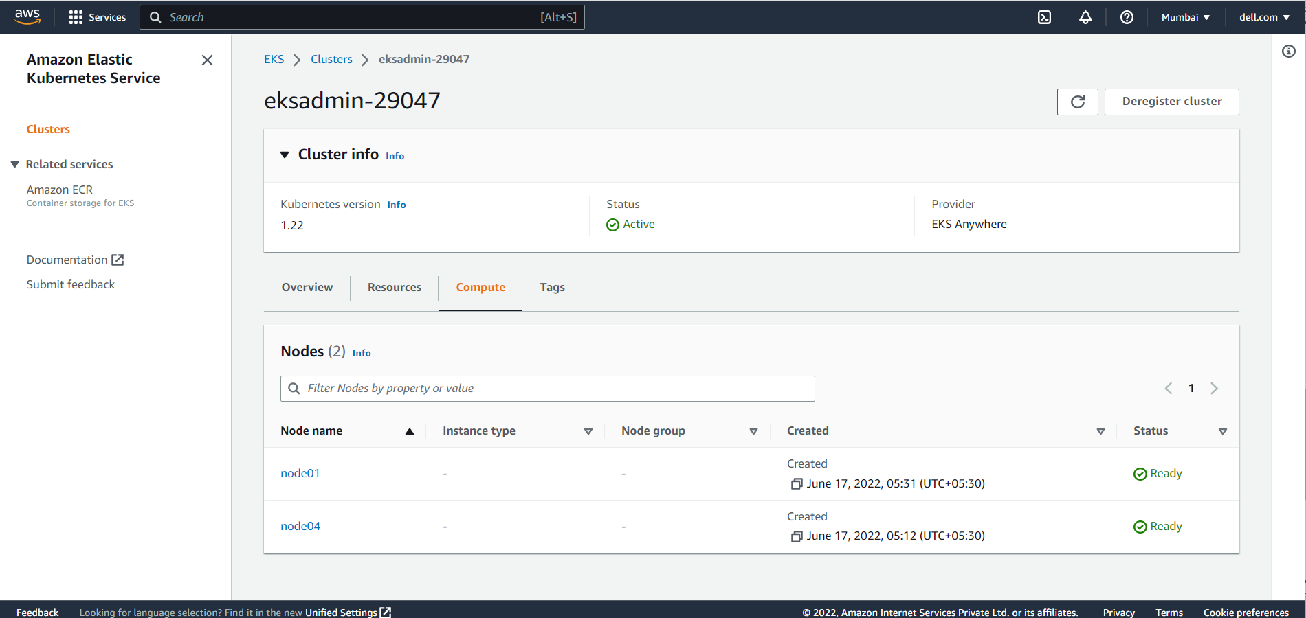 Dashboard
The Compute section shows all the Dell PowerFlex node resources in the Amazon EKS Anywhere Cluster.
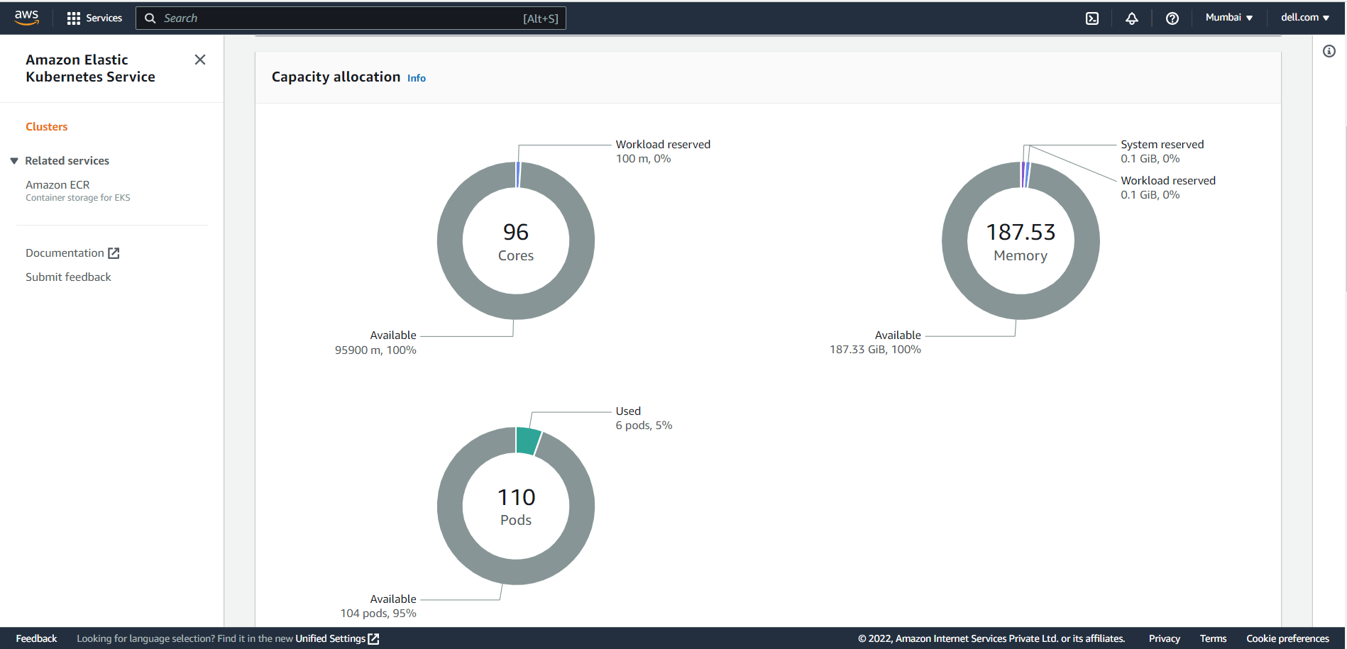 Compute
The Workloads section displays all objects of Type: Deployment, DaemonSet and StatefulSet. Users can select these objects to select a pod-level overview.
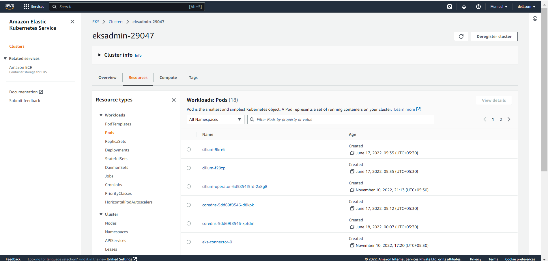 Workloads
Conclusion
In this blog, we have explored the Amazon EKS Connector, and how to connect and register the Kubernetes cluster to the Amazon console. Using the Amazon EKS Connector, organizations can now leverage Amazon EKS Console to bring together both the cloud environment and private infrastructure setups and view them from a single pane of glass.
If you are interested to find out more about how to use Amazon EKS Anywhere and the Amazon EKS Connector in the PowerFlex environment, reach out to your Dell representative.
Resources
- Amazon Elastic Kubernetes Service Anywhere on Dell PowerFlex
- Introducing bare metal deployments for Amazon EKS Anywhere
- Customer Choice Comes First: Dell Technologies and AWS EKS Anywhere

Driving Innovation with the Dell Validated Platform for Red Hat OpenShift and IBM Instana
Wed, 14 Dec 2022 21:20:39 -0000
|Read Time: 0 minutes
“There is no innovation and creativity without failure. Period.” – Brené Brown
In the Information Technology field today, it seems like it’s impossible to go five minutes without someone using some variation of the word innovate. We are constantly told we need to innovate to stay competitive and remain relevant. I don’t want to spend time arguing the importance of innovation, because if you’re reading this then you probably already understand its importance.
What I do want to focus on is the role that failure plays in innovation. One of the biggest barriers to innovation is the fear of failure. We have all experienced some level of failure in our lives, and the costly mistakes can be particularly memorable. To create a culture that fosters innovation, we need to create an environment that reduces the costs associated with failure – these can be financial costs, time costs, or reputation costs. This is why one of the core tenets of modern application architecture is “fail fast”. Put simply, it means to identify mistakes quickly and adjust. The idea is that a flawed process or assumption will cost more to fix the longer it is present in the system. With traditional waterfall processes, that flaw could be present and undetected for months during the development process, and in some cases, even make it through to production.
While the benefits of fail fast can be easy to see, implementing it can be a bit harder. It involves streamlining not just the development process, but also the build process, the release process, and having proper instrumentation all the way through from dev to production. This last part, instrumentation, is the focus of this article. Instrumentation means monitoring a system to allow the operators to:
- See current state
- Identify application performance
- Detect when something is not operating as expected
While the need for instrumentation has always been present, developers are often faced with difficult timelines and the first feature areas that tend to be cut are testing and instrumentation. This can help in the short term, but it often ends up costing more down the road, both financially and in the end-user experience.
IBM Instana is a tool that provides observability of complete systems, with support for over 250 different technologies. This means that you can deploy Instana into the environment and start seeing valuable information without requiring any code changes. If you are supporting web-based applications, you can also take things further by including basic script references in the code to gain insights from client statistics as well.
Announcing Support for Instana on the Dell Validated Platform for Red Hat OpenShift
Installing IBM Instana into the Dell Validated Platform for Red Hat OpenShift can be done by Operator, Helm Chart, or YAML File.
The simplest way is to use the Operator. This consists of the following steps:
- Create the instana-agent project
- Set the policy permissions for the instana-agent service account
- Install the Operator
- Apply the Operator Configuration using a custom resource YAML file
You can configure IBM Instana to point to IBM’s cloud endpoint. Or for high security environments, you can choose to connect to a private IBM Instana endpoint hosted internally.
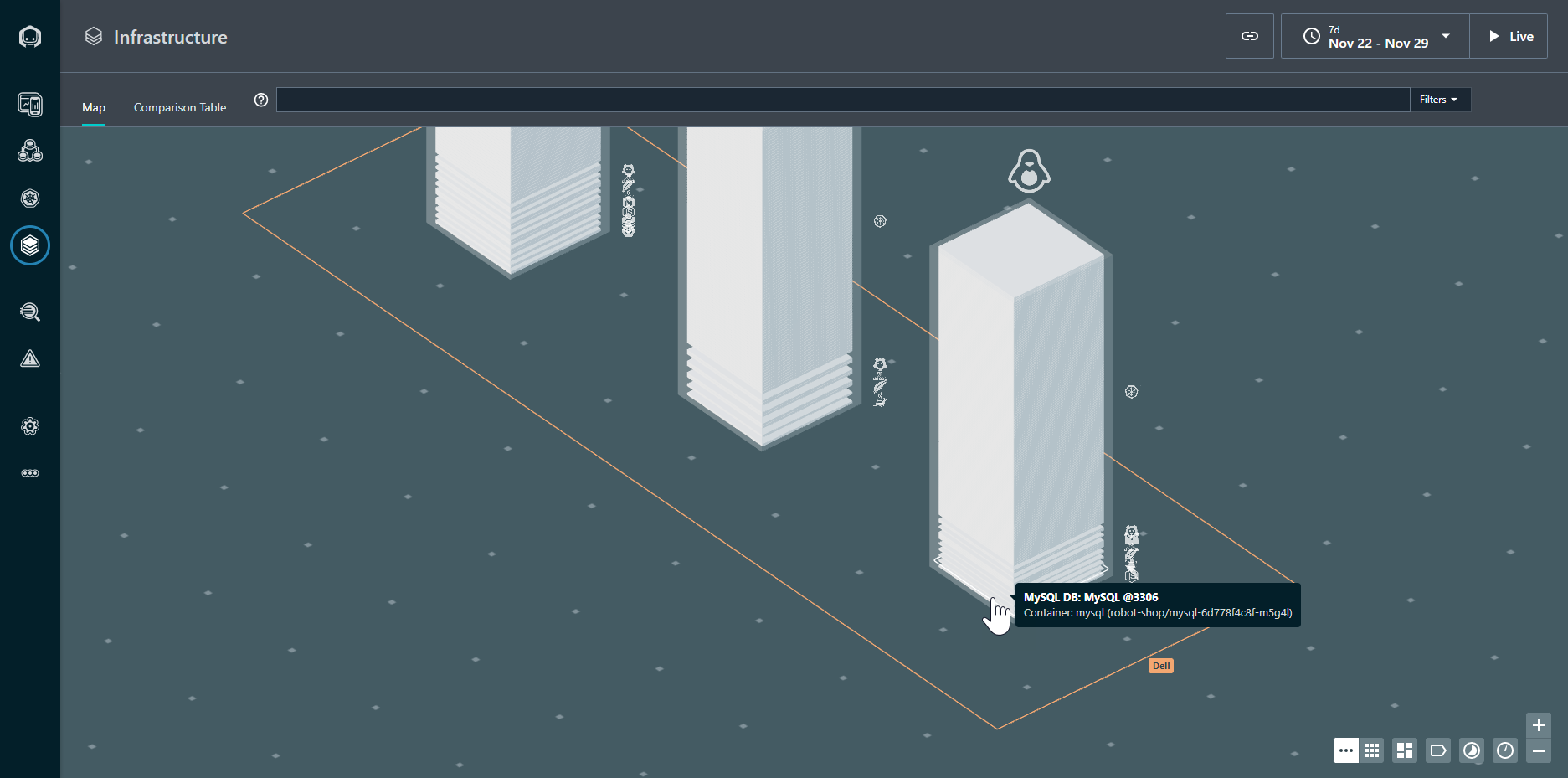
Figure 1. Infrastructure view of the OpenShift Cluster
Once configured, the IBM Instana agent starts sending data to the endpoint for analysis. The graphical view in Figure 1 shows the overall health of the Kubernetes cluster, and the node on which each resource is located. The resources in a normal state are gray: any resource requiring attention would appear in a different color.
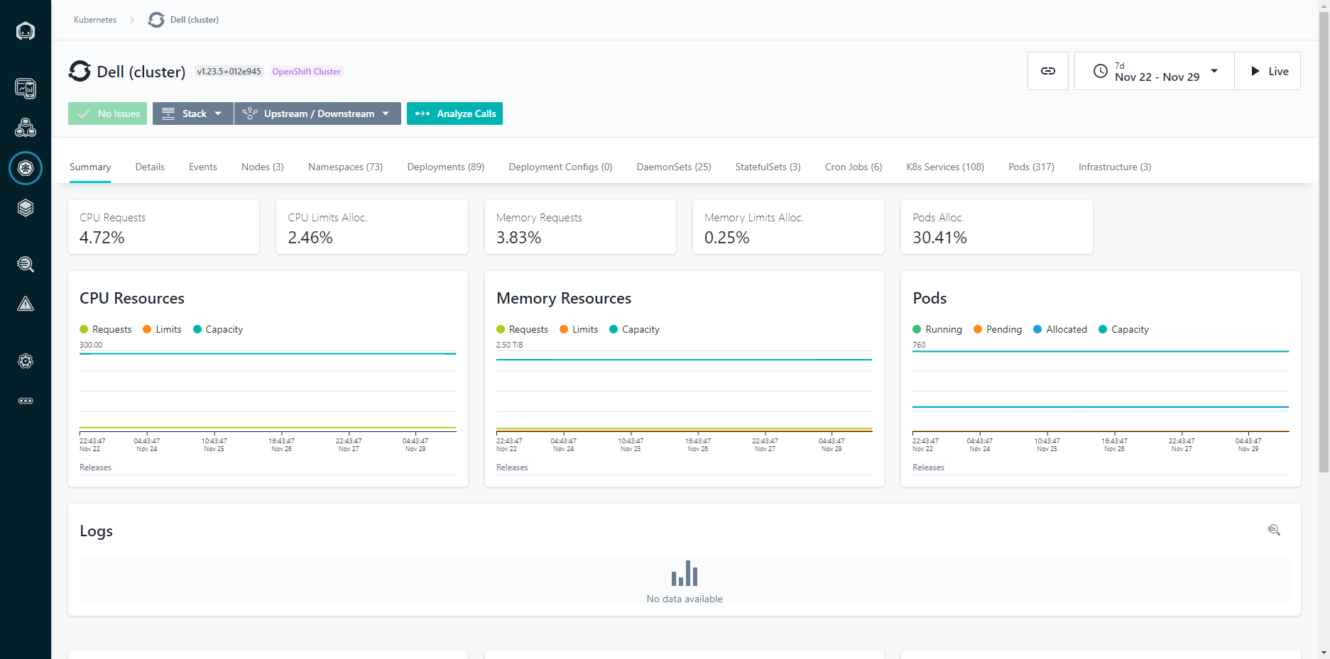
Figure 2: Cluster View
We can also see the metrics across the cluster, including CPU and Memory statistics. The charts are kept in time sync, so if you highlight a given area or narrow the time period, all of the charts remain in the same context. This makes it easy to identify correlations between different metrics and events.
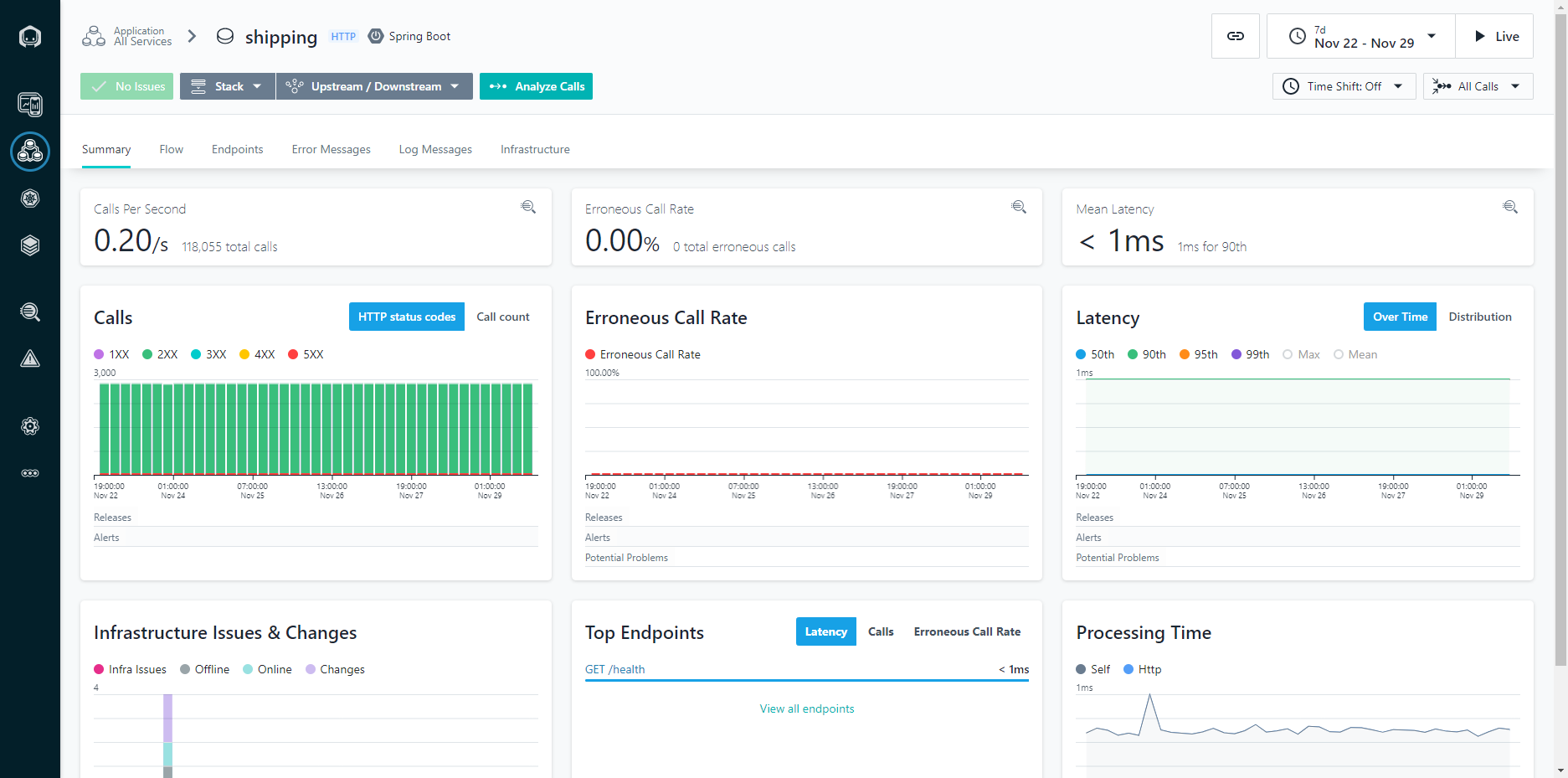
Figure 3: Application Calls View
Looking at the application calls allows you to see how a given application is performing over time. Being able to narrow down to a one second granularity means that you can actually follow individual calls through the system and see things like the parameters passed in the call. This can be incredibly helpful for troubleshooting intermittent application issues.
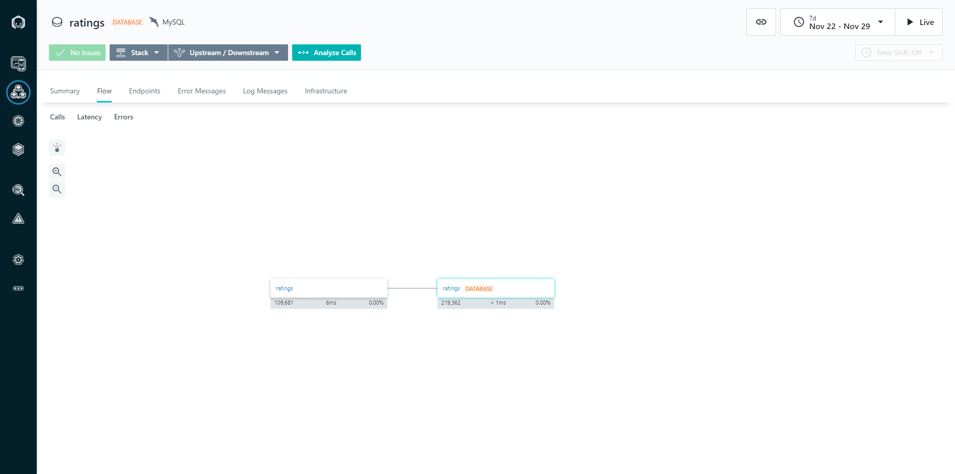
Figure 4: Application Dependencies View
The dependencies view gives you a graphical representation of all the components within a system and how they relate to each other, in a dependency diagram. This is critically important in modern application design because as you implement a larger number of more focused services, often created by different DevOps teams, it can be difficult to keep track of what services are being composed together.
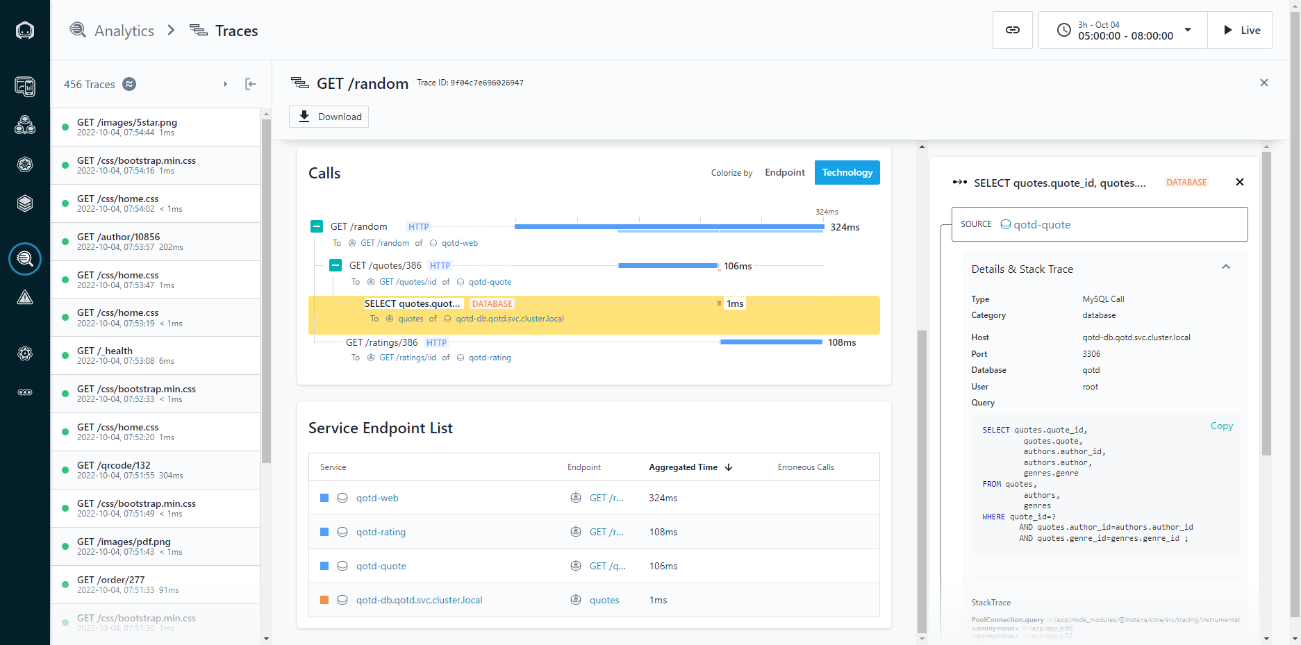
Figure 5: Application Stack Traces
The application stack trace allows you to walk the stack of an application to see what calls were made, and how much time each call took to complete. Knowing that a page load took five seconds can help indicate a problem, but being able to walk the stack and identify that 4.8 seconds was spent running a database query (and exactly what query that was) means that you can spend less time troubleshooting, because you already know exactly what needs to be fixed.
For more information about the Dell Validated Platform for Red Hat OpenShift, see our launch announcement: Accelerate DevOps and Cloud Native Apps with the Dell Validated Platform for Red Hat OpenShift | Dell Technologies Info Hub.
Author: Michael Wells, PowerFlex Engineering Technologist
Twitter: @SqlTechMike
LinkedIn

SQL Server 2022 Backup Using T-SQL and Dell PowerFlex Storage Snapshots
Fri, 04 Nov 2022 04:56:21 -0000
|Read Time: 0 minutes
Introduction
Challenges with conventional database backups
Conventional SQL Server database backups read the data from the host to write it to the backup target location. Similarly, during the restore operation, the data is read back to the host and written to the database datafiles. Although this method allows both incremental and full backups, it poses significant challenges to mission-critical databases:
- Conventional backup and restore operations use host resources, such as CPU, memory, and I/O, which may end up impacting database performance.
- As database capacity grows, backing up the larger dataset takes longer time that can range from minutes to hours. This issue gets worse during restore operations when the business is waiting for the restore to finish and for the database to become online again.
Why Storage snapshots?
Many companies are using storage snapshots to overcome the above challenges. Dell PowerFlex software-defined storage snapshots provide the following advantages for SQL Server backup:
- You can create and restore storage snapshots in seconds regardless of the database size.
- Since snapshot creation or restore operation is so fast, the database host resources are not impacted.
- PowerFlex storage snapshots are consistent and writable, allowing the snapshot to serve as a point-in-time copy (for purposes such as mounting test, development, or reporting database copies).
- PowerFlex snapshots are thin and keep only the data changes that happened since the snapshot was created hence providing space efficiency better than incremental backups.
- Final and most important advantage is that together with Microsoft APIs, you can use PowerFlex snapshots for SQL Server backup and restore operations.
SQL Server storage backup APIs
It is not new for the SQL Server backup process to take advantage of storage snapshots. This has been done for many years using Virtual Device Interface (VDI) or Volume Shadow Copy Service (VSS) APIs. By using these APIs and backup software, together with PowerFlex, provides all the storage snapshot advantages that are mentioned above, and allows the snapshots to be valid backups of the database.
The new Transact-SQL snapshot backup feature
With SQL Server 2022, Microsoft introduced a new way of creating database backups using storage snapshots: Transact-SQL (T-SQL) snapshot backup. This method does not require the use of either VDI or VSS APIs and can work for both Windows and Linux.
The new T-SQL snapshot backup workflow is as follows:
- A T-SQL backup command is issued, that stops write operations to the database by acquiring a lock. The command can include one, multiple, or all databases.
- The backup administrator takes a storage-level snapshot of the database (or databases).
- A second T-SQL backup command is issued, resuming databases operations and saving the backup’s metadata to a file. This metadata file is required if the storage snapshot is used for database recovery.
Here's an example of using a T-SQL snapshot:
The following example shows how to perform backup and recovery operations on a database that is called tpcc, using the new T-SQL snapshot backup feature with PowerFlex snapshots.
Backup operation
Backup step 1: Suspend database
Suspend the database using the following T-SQL command:
ALTER DATABASE tpcc SET SUSPEND_FOR_SNAPSHOT_BACKUP = ON;
In this command, a single-user database is suspended, blocking any further operations. The following output shows successful suspension:
Database 'tpcc' acquired suspend locks in session 54.
I/O is frozen on database tpcc. No user action is required. However, if I/O is not resumed promptly, you could cancel the backup.
Database 'tpcc' successfully suspended for snapshot backup in session 54.
Note: For more information about how to suspend multiple or all user databases, see Microsoft documentation.
Backup step 2: Take a PowerFlex snapshot of database volumes
Once the database is suspended, a snapshot of the database volumes is created using PowerFlex Manager UI, REST APIs, or PowerFlex Command Line Interface (CLI).
In this example, the snapshot includes both the datafiles and transaction log volumes. This allows the snapshot to serve multiple purposes:
- To create stand-alone database instances for purposes such as reporting, testing, and development (as it contains a consistent image of both the data and log).
- To restore both the data and log if both were corrupted. In that case, both the data and log volumes are restored, and the database is recovered to the last transaction log backup.
- If the active transaction log survived the disaster, only the data volumes are restored, and the database can perform a full recovery of all committed transactions.
The following figure is an example of creating a snapshot using PowerFlex Manager UI:
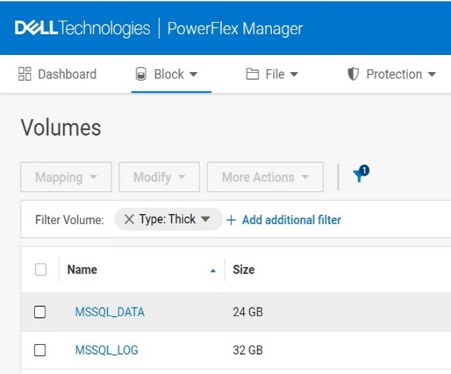
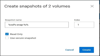
Figure1. Creating a snapshot using PowerFlex CLI
Run the following command to create a snapshot using PowerFlex CLI:
scli --snapshot_volume --volume_name MSSQL_DATA, MSSQL_LOG --snapshot_name MSSQL_DATA-snap-1,MSSQL_LOG-snap-1 --read_only
Sample output:
Snapshots on 2 volumes created successfully
Consistency group ID: b10f52c800000002
Source volume MSSQL_DATA => 20f0895f00000004 MSSQL_DATA-snap-1
Source volume MSSQL_LOG => 20f0896000000005 MSSQL_LOG-snap-1
Backup step 3: Take T-SQL metadata backup of the database
When the snapshot is created, use the following command to create the metadata file and resume database write operations:
BACKUP DATABASE tpcc TO DISK = 'C:\mssql_metadata_backup\tpcc_metadata.bkm' WITH METADATA_ONLY,MEDIANAME='PowerFlex-MSSQL_DATA-Snapshot-backup';
In this step, the metadata file of the database tpcc is stored in the specified path. This command also releases the database lock and allows the database operations to resume.
Sample output:
I/O was resumed on database tpcc. No user action is required.
Database 'tpcc' released suspend locks in session 54.
Database 'tpcc' originally suspended for snapshot backup in session 54 successfully resumed in session 54.
Processed 0 pages for database 'tpcc', file 'tpcc' on file 5.
BACKUP DATABASE successfully processed 0 pages in 0.003 seconds (0.000 MB/sec.
Simulating a database corruption
There could be different reasons for a database to require recovery, such as due to datafiles deletion, disks being formatted or overwritten, physical block corruptions, and so on. In this example, we will drop a large table and recover the database to a point in time before the drop.
To show the database recovery that includes data that is added after the snapshot creation, we create a new table after the snapshot is taken and insert a record to that table. That record is a part of the next transaction log backup. Finally, we drop the customer table and validate the database recovery.
Step 1: Create a new table after the snapshot was taken, and insert a known record to the table
Run the following command to create a table and insert a known record into the table:
create table returns ( returnID int, returnName varchar(255));
insert into returns values (1,'sampleValue');
returnID | returnName |
1 | sampleValue |
Step 2: Take a transaction log backup
The following command creates a log backup which includes the returns table data. The database recovery uses this log backup.
BACKUP LOG tpcc TO DISK = 'C:\mssql_tail_log_backup\tpcc_tail_log_before_disaster.bkm';
Note: It is a best practice to create periodic transaction log backups, as demonstrated above.
Step 3: Simulate a database corruption
For demonstration purposes, we simulate database corruption by dropping the customer table by running the following command:
drop table tpcc.dbo.customer;
Recovery operations
Database recovery happens in two steps:
- First, we restore the database data using the storage snapshot.
- Next, we recover the database using the transaction log backup.
Recovery step 1: Bring the database offline
Before we restore the database, if it is still up (depends on the type of corruption), set the database offline by running the following command:
alter database tpcc set offline;
Recovery step 2: Bring the database disks offline
Before restoring the storage snapshot of the database disks, set the disks offline to avoid any leftover locks. You can use either disk management or PowerShell commands.
Set-Disk -Number 1 -isOffline $True
Note: In this example only the data disk is set to offline, as the active transaction log remained intact and there is no reason to overwrite it with the log snapshot.
Recovery step 3: Restore the database data volume snapshot
Restore the PowerFlex database data volumes using the snapshot. This can be done from the PowerFlex UI, REST APIs, or PowerFlex CLI.
Following is an example of restoring the snapshot using PowerFlex CLI:
scli --overwrite_volume_content --source_vol_name MSSQL_DATA-snap-1 --destination_vol_name 'MSSQL_DATA'
Sample output:
Overwrite volume content can remove data and should not be called during I/O operations or on mounted volumes. Press 'y' and then Enter to confirm: y
Overwrite volume content was completed successfully
Recovery step 4: Bring the database disks online
Bring the database volumes back online either using Disk management or PowerShell commands.
Set-Disk -Number 1 -isOffline $False
Recovery step 5: Bring the database online
Bring the database tpcc back online by using following command:
alter database tpcc set online;
Recovery step 6: Restore the snapshot backup metadata
Use the metadata file captured during the snapshot backup to make the SQL Server aware of the restored snapshot.
Note: Before this can be done, SQL Server requires to perform a backup of active transaction log content. Do this first, followed by the database restore command.
Take a T-SQL backup of the active transaction log by running the following command:
BACKUP LOG tpcc TO DISK = 'C:\mssql_tail_log_backup\tpcc_tail_log_after_disaster.bkm' WITH NORECOVERY;
Restore the snapshot backup metadata by running the following command:
RESTORE DATABASE tpcc FROM DISK = 'C:\mssql_metadata_backup\tpcc_metadata.bkm' WITH METADATA_ONLY, NORECOVERY;
Note: Since the command specifies METADATA_ONLY, SQL Server knows that the database data was restored from a storage snapshot. If NORECOVERY is used, the database goes to a restoring state, as it is waiting to apply transaction log backups to make it consistent.
Recovery step 7: Apply transaction log backups
Restore the appropriate transaction log backup or backups. In the following example, we restore the log backup taken after the returns table was created, and before the customer table is dropped.
RESTORE LOG tpcc FROM DISK = C:\mssql_tail_log_backup\tpcc_tail_log_before_disaster.bkm' WITH RECOVERY;
Note: If there are multiple transaction logs to restore, use the WITH NORECOVERY option with all but the last one. The last RESTORE LOG command uses WITH RECOVERY, signifying that no more recovery is needed.
When this operation is complete, the database is operational and contains all the restored transactions (including the newly created returns table).
Conclusion
With the new SQL Server 2022 T-SQL Snapshot backup feature, it is possible to perform database backups based on the PowerFlex storage snapshots, without relying on additional backup tools. This process can be automated to achieve faster and reliable backup solutions for mission-critical SQL Server databases, for both Windows and Linux operating systems.
Also, for related information about Dell PowerStore see the blog post: SQL Server 2022 – Time to Rethink your Backup and Recovery Strategy.
Accelerate DevOps and Cloud Native Apps with the Dell Validated Platform for Red Hat OpenShift
Thu, 15 Sep 2022 13:28:43 -0000
|Read Time: 0 minutes
Today we announce the release of the Dell Validated Platform for Red Hat OpenShift. This platform has been jointly validated by Red Hat and Dell, and is an evolution of the design referenced in the white paper “Red Hat OpenShift 4.6 with CSI PowerFlex 1.3.0 Deployment on Dell EMC PowerFlex Family”.
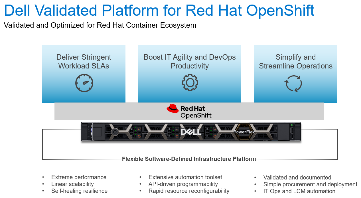
Figure 1: The Dell Validated Platform for Red Hat OpenShift
The world is moving faster and with that comes the struggle to not just maintain, but to streamline processes and accelerate deliverables. We are no longer in the age of semi-annual or quarterly releases, as some industries need multiple releases a day to meet their goals. To accomplish this requires a mix of technology and processes … enter the world of containers. Containerization is not a new technology, but in recent years it has picked up a tremendous amount of steam. It is no longer just a fringe technology reserved for those on the bleeding edge; it has become mainstream and is being used by organizations large and small. However, technology alone will not solve everything. To be successful your processes must change with the technology – this is where DevOps comes in. DevOps is a different approach to Information Technology; it involves a blending of resources usually separated into different teams with different reporting structures and often different goals. It systematically looks to eliminate process bottlenecks and applies automation to help organizations move faster than they ever thought possible. DevOps is not a single process, but a methodology that can be challenging to implement.
Why Red Hat OpenShift?
Red Hat OpenShift is an enterprise-grade container orchestration and management platform based on Kubernetes. While many organizations understand the value of moving to containerization, and are familiar with the name Kubernetes, most don’t have a full grasp of what Kubernetes is and what it isn’t. OpenShift uses their own Kubernetes distribution, and layers on top critical enterprise features like:
- Built-in underlying hardware management and scaling, integrated with Dell iDRAC
- Multi-Cluster deployment, management, and shift-left security enforcement
- Developer Experience – CI/CD, GitOps, Pipelines, Logging, Monitoring, and Observability
- Integrated Networking including ServiceMesh and multi-cluster networking
- Integrated Web Console with distinct Admin and Developer views
- Automated Platform Updates and Upgrades
- Multiple workload options – containers, virtual machines, and serverless
- Operators for extending and managing additional capabilities
All these capabilities mean that you have a full container platform with a rigorously tested and certified toolchain that can accelerate your development, and reduce the costs associated with maintenance and downtime. This is what has made OpenShift the number 1 container platform in the market.
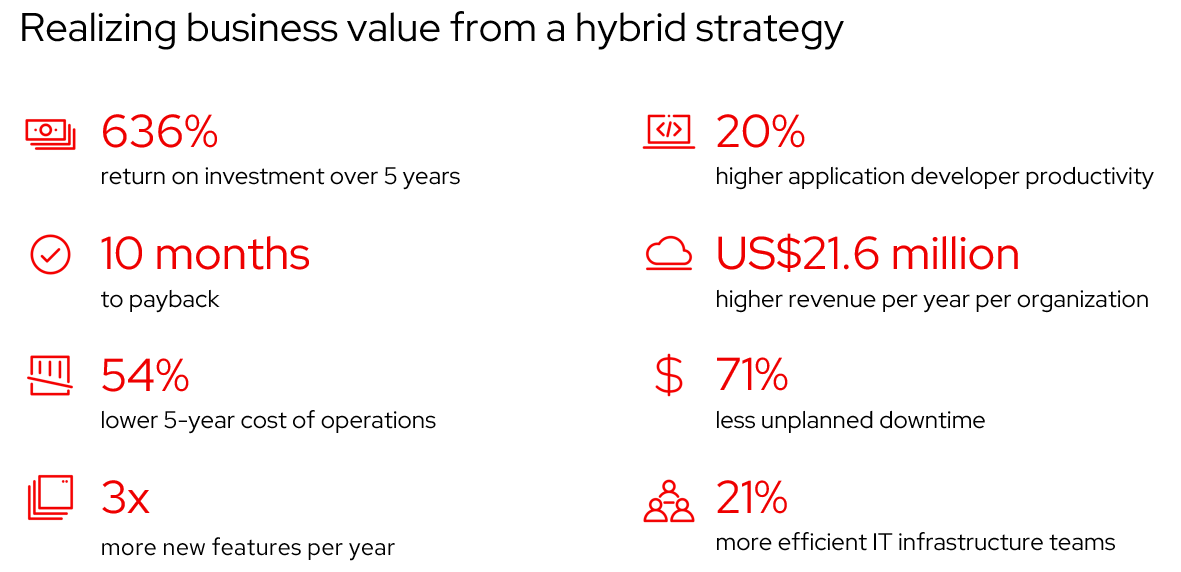
Figure 2: Realizing business value from a hybrid strategy - Source: IDC White Paper, sponsored by Red Hat, "The Business Value of Red Hat OpenShift", doc # US47539121, February 2021.
Meeting the performance needs
Scalable container platforms like Red Hat OpenShift work best when paired with a fast, scalable infrastructure platform, and this is why OpenShift, and Dell PowerFlex are the perfect team. With PowerFlex, organizations can have a single software-defined platform for all their workloads, from bare metal, to virtualized, to containerized. All on a blazing-fast infrastructure that can scale to thousands of nodes. Not to mention the API-driven architecture of PowerFlex fits perfectly in a methodology centered on automation. To help jumpstart customers on their automation journey we have already created robust infrastructure and DevOps automation through our extensive tooling that includes:
- Dell Container Storage Modules (CSM)/Container Storage Interface (CSI) Plugins
- Ansible Modules
- AppSync Integration
Being software-defined means that PowerFlex can deliver linear performance by being able to balance data across all nodes. This ensures that you can spread the work out over the cluster to scale well beyond the limits of the individual hardware components. This also allows PowerFlex to be incredibly resilient, capable of seamlessly recovering from individual component or node failures.
Putting it all together
Introducing the Dell Validated Platform for Red Hat OpenShift, the latest collaboration in the long 22-year partnership between Red Hat and Dell. This platform brings together the power of Red Hat OpenShift with the flexibility and performance of Dell PowerFlex into a single package.
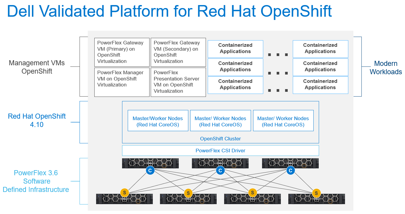
Figure 3: The Dell Validated Platform for Red Hat OpenShift Architecture
This platform uses PowerFlex in a 2-tier architecture to give you optimal performance, and the ability to scale storage and compute independently, up to thousands of nodes. We are also taking advantage of Red Hat capabilities to run PowerFlex Manager and its accompanying services in OpenShift Virtualization to make efficient use of compute nodes and minimize the required hardware footprint.
The combined platform gives you the ability to become more agile and increase productivity through the extensive automation already available, along with the documented APIs to extend that automation or create your own.
This platform has been fully validated by both Dell and Red Hat, so you can run it with confidence. We have also streamlined the ordering process, so the entire platform can be acquired directly from Dell, including the Red Hat software and subscriptions. All of this is implemented using Dell’s ProDeploy services to ensure that the platform is implemented optimally and gets you up and running faster. This means you can start realizing the value of the platform faster, while reducing risk.
If you are interested in getting more information about the Dell Validated Platform for Red Hat OpenShift please contact your Dell representative.
Authors:
Michael Wells, PowerFlex Engineering Technologist
Twitter: @SqlTechMike
LinkedIn
Rhys Oxenham, Director, Customer & Field Engagement

New File Services Capabilities of PowerFlex 4.0
Tue, 16 Aug 2022 14:56:28 -0000
|Read Time: 0 minutes
“Just file it,” they say, and your obvious question is “where?” One of the new features introduced in PowerFlex 4.0 is file services. Which means that you can file it in PowerFlex. In this blog we’ll dig into the new file service capabilities offered with 4.0 and how they can benefit your organization.
I know that when I think of file services, I think back to the late 90s and early 2000s when most organizations had a Microsoft Windows NT box or two in the rack that provided a centralized location on the network for file storage. Often it was known as “cheap and deep storage,” because you bought the biggest cheapest drives you could to install in that server with RAID 5 protection. After all, most of the time it was user files that were being worked on and folks already had a copy saved to their desktop. The file share didn’t have to be fast or responsive, and the biggest concern of the day was using up all the space on those massive 146 GB drives!
That was then … today file services do so much more. They need to be responsive, reliable, and agile to handle not only the traditional shared files, but also the other things that are now stored on file shares.
The most common thing people think about is user data from VDI instances. All the files that make up a user’s desktop, from the background image to the documents, to the customization of folders, all these things and more are traditionally stored in a file share when using instant clones.
PowerFlex can also handle powerful, high performance workload scenarios such as image classification and training. This is because of the storage backend. It is possible to rapidly serve files to training nodes and other high performance processing systems. The storage calls can go to the first available storage node, reducing file recall times. This of course extends to other high speed file workloads as well.
Beyond rapid recall times, PowerFlex provides massive performance, with 6-nines of availability1, and native multi-pathing. This is a big deal for modern file workloads. With VDI alone you need all of these things. If your file storage system can’t deliver them, you could be looking at poor user experience or worse: users who can’t work. I know, that’s a scary thought and PowerFlex can help significantly lessen those fears.
In addition to the performance, you can manage the file servers in the same PowerFlex UI as the rest of your PowerFlex environment. This means there is no need to learn a new UI, or bounce all over to set up a CIFS share—it’s all at your fingertips. In the UI it’s as simple as changing the tab to go from block to file on many screens.
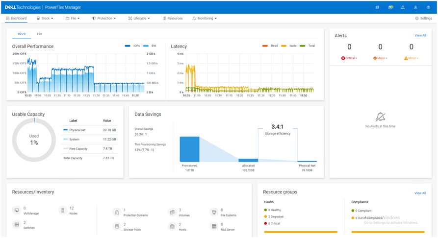
The PowerFlex file controllers (physical) host the software for the NAS servers (logical). You start with two file controllers and can grow to 16 file controllers. Having various sizes of file controllers allows you to customize performance to meet your environment’s needs. The NAS Servers are containerized logical segmentations that provide the file services to the clients, and you can have up to 512 in a cluster. They are responsible for namespaces, security policies, and serving file systems to the clients.
Each of the file volumes that are provided by the file services are backed by PowerFlex volumes. This means that you can increase file service performance and capacity by adding PowerFlex nodes to the storage layer just like a traditional block storage instance. This allows you to independently scale performance and capacity, based on your needs.
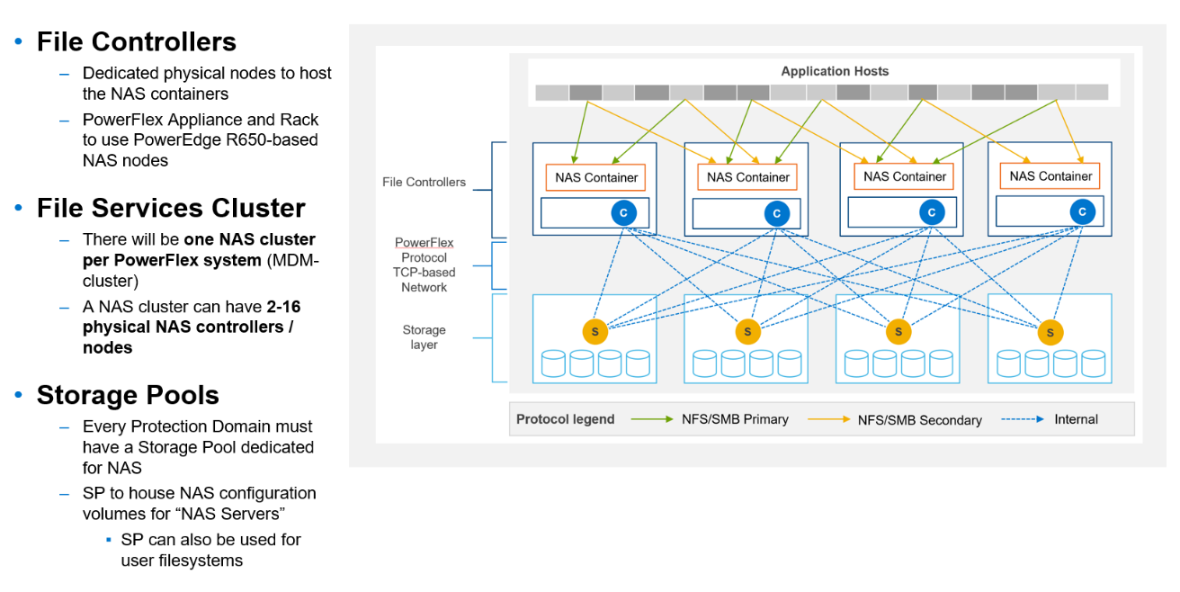
The following table provides some of the other specs you might be wondering about.
Feature | Max |
FS Capacity | 256 TB |
Max file size | 64 TB |
# of files | 10 billion |
# of ACLs | 4 million |
User File Systems | 4096 |
Snaps per File System | 126 |
CIFS | 160000 |
NFS exports | 80000 |
Beyond the architectural goodness, file storage is something that can be added later to a PowerFlex environment. Thus, you aren’t forced to get something now because you “might” need it later. You can implement it when that project starts or when you’re ready to migrate off that single use file server. You can also grow it as you need, by starting small and growing to a large deployment with hundreds of namespaces and thousands of file systems.
With PowerFlex when someone says “file it,” you’ll know you have the capacity to support that file and many more. PowerFlex file services provide the capability to deliver the power needed for even the most demanding file-based workloads like VDI and AI/ML data classification systems. It’s as easy managing the environment as it is integrated into the UI.
If you are interested in finding out more about PowerFlex file services, contact your Dell representative.
Author: Tony Foster
Twitter: @wonder_nerd
LinkedIn
1 Workload performance claims based on internal Dell testing. (Source: IDC Business Value Snapshot for PowerFlex – 2020.)

Introducing NVMe over TCP (NVMe/TCP) in PowerFlex 4.0
Fri, 26 Aug 2022 18:59:38 -0000
|Read Time: 0 minutes
Anyone who has used or managed PowerFlex knows that an environment is built from three lightweight software components: the MDM, the SDS, and the SDC. To deploy a PowerFlex environment, the typical steps are:
- Deploy an MDM management cluster
- Create a cluster of storage servers by installing and configuring the SDS software component
- Add Protection Domains and Storage Pools
- Install the SDC onto client systems
- Provision volumes and away you go!!*
*No requirement for multipath software, this is all handled by the SDC/SDS
There have been additions to this over the years, such as an SDR component for replication and the configuration of NVDIMM devices to create finegranularity storage pools that provide compression. Also added are PowerFlex rack and appliance environments. This is all automated with PowerFlex Manager. Fundamentally, the process involves the basic steps outlined above.
So, the question is why would we want to change anything from an elegant solution that is so simple?
This is due to where the SDC component ‘lives’ in the operating system or hypervisor hosting the application layer. Referring to the diagram below, it shows that the SDC must be installed in the kernel of the operating system or hypervisor, meaning that the SDC and the kernel must be compatible. Also the SDC component must be installed and maintained, it does not just ‘exist’.
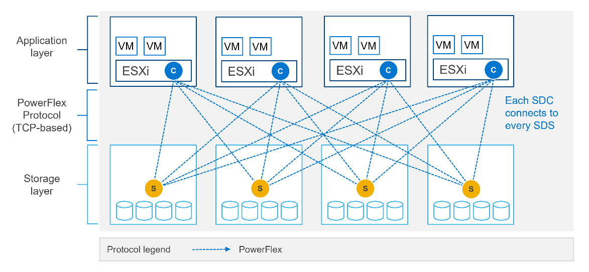
In most cases, this is fine and there are no issues whatsoever. The PowerFlex development team keeps the SDC current with all the major operating system versions and customers are happy to update the SDC within their environment when new versions become available.
There are, however, certain cases where manual deployment and management of the SDC causes significant overhead. There are also some edge use cases where there is no SDC available for specific operating systems. This is why the PowerFlex team has investigated alternatives.
In recent years, the use of Non-Volatile Memory Express (NVMe) has become pervasive within the storage industry. It is seen as the natural replacement to SCSI, due to its simplified command structure and its ability to provide multiple queues to devices, aligning perfectly with modern multi-core processors to provide very high performance.
NVMe appeared initially as a connection directly to disks within a server over a PCIe connection, progressing to being used over a variety of fabric interconnects.
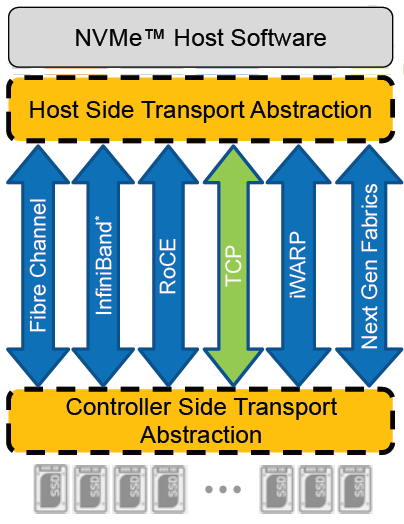
Added to this is the widespread support for NVMe/TCP across numerous operating system and hypervisor vendors. Most include support natively in their kernels.
There have been several announcements by Dell Technologies over the past months highlighting NVMe/TCP as an alternative interconnect to iSCSI across several of the storage platforms within the portfolio. It is therefore a natural progression for PowerFlex to also provide support for NVMe/TCP, particularly because it already uses a TCP-based interconnect.
PowerFlex implements support for NVMe/TCP with the introduction of a new component installed in the storage layer called the SDT.
The SDT is installed at the storage layer. The NVMe initiator in the operating system or hypervisor communicates with the SDT, which then communicates with the SDS. The NVMe initiator is part of the kernel of the operating system or hypervisor.
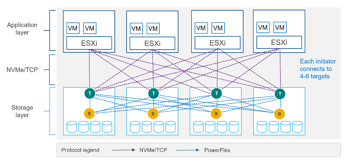
Of course, because PowerFlex is so ‘flexible,’ both connection methods (SDC and NVMe/TCP) are supported at the same time. The only limitation is that a volume can only be presented using one protocol or the other.
For the initial PowerFlex 4.0 release, the VMware ESXi hypervisor is supported. This support starts with ESXi 7.0 U3f. Support for Linux TCP initiators is currently in “tech preview” as the initiators continue to grow and mature, allowing for all failure cases to be accounted for.
NVMe/TCP is a very powerful solution for the workloads that take advantage of it. If you are interested in discovering more about how PowerFlex can enhance your datacenter, reach out to your Dell representative.
Authors:
Kevin M Jones, PowerFlex Engineering Technologist.
Tony Foster, Senior Principal Technical Marketing Engineer.
Twitter: @wonder_nerd
LinkedIn

An Introduction to the Unified PowerFlex Manager Platform
Tue, 16 Aug 2022 14:56:28 -0000
|Read Time: 0 minutes
We have all heard the well-known quote that “Change is the only constant in life”. Nowhere is this concept more apparent than in the world of IT, where digital transformation has become accepted as a fact of life and standing still is not an option. Anyone - or anything - that stands still in the world of IT faces becoming extinct, or irrelevant, when faced with responding to the ever-changing challenges that businesses must solve to survive and grow in the 21st Century. IT infrastructure has had to evolve to provide the answers needed in today’s business landscape – a world where Dev Ops and automation is driving business agility and productivity, where flexibility is key, and where consolidation and optimization are essential in the face of ever-shrinking budgets.
When dealing with the ever-changing IT landscape, software-defined infrastructure is ideally suited to delivering answers for business change. Indeed, many Dell Technologies customers choose PowerFlex as their software-defined infrastructure solution of choice because as a product, it has changed and evolved as much as customers themselves have had to change and evolve.
However, there are times when evolution itself is not enough to bring about inevitable changes that must occur - sometimes there must be a revolution! When it comes to IT infrastructure, managers are often given the “coin toss” of only being able to pick from either evolution or revolution. Faced with such a decision, managers often choose evolution over revolution – a simpler, more palatable path.
This was the dilemma that PowerFlex developers faced – continue with various separate management planes or unify them. Our developers were already planning to introduce several new features in PowerFlex 4.0, including PowerFlex File Services and NVMe/TCP connectivity. Adding new features to existing products generally means having to change the existing management tools and user interfaces to integrate the new functionality into the existing toolset. PowerFlex has a broad product portfolio and a broad set of management tools to match, as shown in the following figure. The uptake of customers using PowerFlex Manager was proof-positive that customers liked to use automation tools to simplify their infrastructure deployments and de-risk life-cycle management (LCM) tasks.
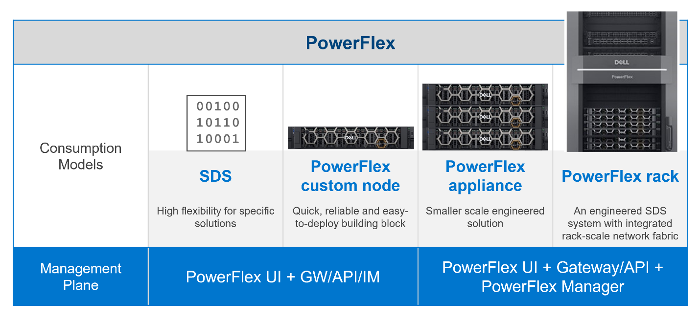
Figure 1: PowerFlex management planes, before PowerFlex 4.0
In addition to the multiple demands they had to contend with, the PowerFlex team was aware that new, as-yet unthought of demands would inevitably come to the surface in the future, as the onward progression of IT transformation continues.
Aiming to enhance the hybrid datacenter infrastructure that our customers are gravitating towards, simply evolving the existing management planes was not going to be sufficient. The time had come for revolution instead of evolution for the world of PowerFlex management.
The answer is simple to state, but not easy to achieve – design a new Management & Orchestration platform that reduces complexity for our customers. The goal was to simplify things by having a single management plane that is suitable for all customers, regardless of their consumption model. Revolution indeed!
Given a blank drawing board, the PowerFlex Team drew up a list of requirements needed for the new PowerFlex Management stack. The following is a simplified list:
- Unified RBAC and User Management. Implement single sign-on for authentication and authorization, ensuring that only a single set of roles is needed throughout PowerFlex.
- Have a single, unified web UI – but make it extensible, so that as new functionality becomes available, it can easily be added to the UI without breaking it. The addition of “PowerFlex File Services” with PowerFlex 4.0 is proof that this approach works!
- Create a single REST endpoint for all APIs, to ensure that both the legacy and the modern endpoints are accessible through a standardized PowerAPI.
- Ensure that the management stack is highly available, self-healing, and resilient.
- Centralize all events from all PowerFlex components – the SDS itself, switches, nodes, and resources, so that it simplifies the generation of alerts and call home operations.
Faced with this wish list, the team decided to build a new “unified” PowerFlex Manager to satisfy the “one management pane” requirement. But how to deliver a UI that is flexible enough to deal with serving different applications from a single web UI? How can this support a highly available and extensible management platform? It became clear to all that a new M&O stack was needed to achieve these aims and that the answer was to leverage the use of microservices, running as part of a larger, containerized platform.
Around the same time, the Dell ISG Development Team had been working internally on a new shared services platform. It was now ready for primetime. This Dell-developed Kubernetes distribution provides internal shared services that are required by nearly any IT infrastructure: logging services, database-as-a-service, certificate management, identity management, secrets management. It also manages Docker and Helm registries.
Using this new platform as a base, the PowerFlex Team then deployed additional microservices on top of it to micro-manage services specific to PowerFlex. Different micro-frontends can be called upon, depending on the operational context. While the overall PowerFlex Manager GUI application can be run as one “generic” UI, it can call out to different micro-frontends when required. This means that implementing and using microservices simplifies the transfer of previous element managers into the unified PowerFlex Manager world. For example, the traditional PowerFlex Block UI (the PowerFlex Presentation Server UI from PowerFlex 3.6) is now treated as one microservice, while the PowerFlex Manager Lifecycle Manager is now handled by several microservices all working in tandem. Plus, it becomes simple to add a new micro-frontend to handle the “PowerFlex File” functionality that has been released with PowerFlex 4.0 into the GUI as well. Because each GUI section now has its own micro-frontend, the UI now meets the “flexible and extensible” requirement.
This flexibility gives our existing PowerFlex customers assurance as they move from version 3.6 to 4.0. And equally important, it means there is now a single unified manager that can cover all consumption models, as shown in the following figure:
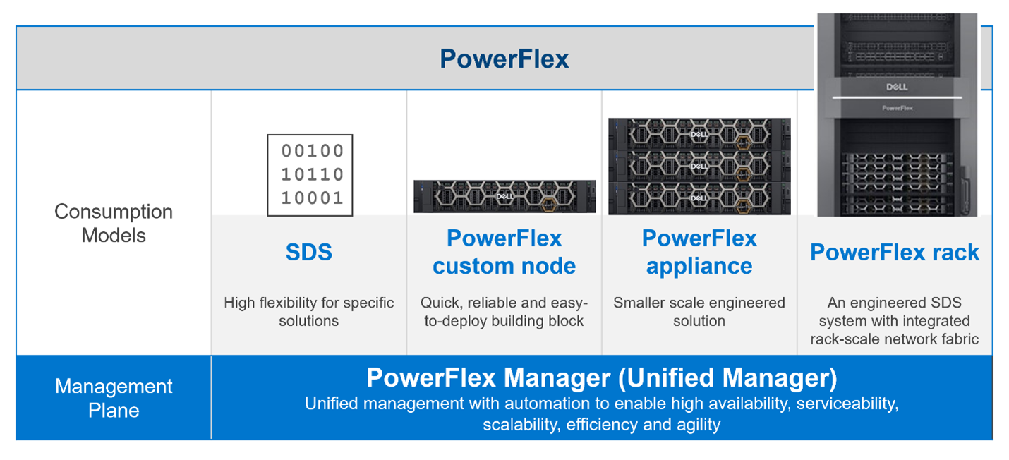
Figure 2. The unified PowerFlex Management Plane with PowerFlex 4.0
Finally, what does the new unified PowerFlex Manager look like? Existing PowerFlex users will be pleased to see that the new unified PowerFlex Manager still has the same “look and feel” that PowerFlex Manager 3.x had. We hope this will make it easier for operations staff when they decide to upgrade from PowerFlex 3.x to PowerFlex 4.0. The following figures show the Block and File Services tabs respectively:
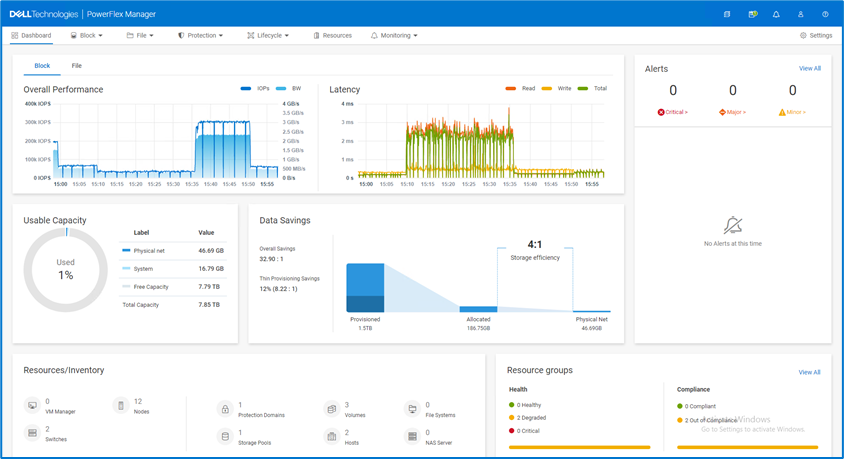
Figure 3. The unified PowerFlex Manager 4.0 Dashboard

Figure 4. The unified PowerFlex Manager 4.0 – Resources
While we cannot stop progress, we can always excel when faced with an ever-changing landscape. Customers already choose PowerFlex when they want to deploy highly performant, scalable, resilient, and flexible software-defined infrastructures. They can now also choose to move to PowerFlex 4.0, safe in the knowledge that they have also future-proofed the management of their infrastructure. While they may not know what changes are in store, the unified PowerFlex Manager Platform will help ensure that those future changes, whatever they are, can be handled easily when deployed on top of PowerFlex.
The enhancements made to PowerFlex provide many possibilities for modern datacenters and their administrators, especially when faced with the constant digital transformation seen in IT today. This is seen in how the various PowerFlex management consoles have been unified to allow continued change and growth to meet organizations’ needs. Yet, there is also continuity with previous versions of the UI, ensuring an easy transition for users when they have migrated to 4.0. If you are interested in finding out more about PowerFlex and all it has to offer your organization, reach out to your Dell representative.
Authors: Simon Stevens, PowerFlex Engineering Technologist, EMEA.
Tony Foster, Senior Principal Technical Marketing Engineer.
Twitter: @wonder_nerd
LinkedIn

PowerFlex and PowerProtect: Keeping Your IT Kingdom Free of Ransomware
Wed, 13 Jul 2022 13:05:58 -0000
|Read Time: 0 minutes
“To be, or not to be? That is the question.” Sadly, the answer for many organizations is “to be” the victim of ransomware. In 2020, the Internet Crime Complaint Center (IC3), a department of the FBI, received “2,474 complaints identified as ransomware with adjusted losses of over $29.1 million” according to their annual report.
This report is just the tip of the iceberg. Some organizations choose not to report ransomware attacks and keep the attacks out of the news. Reporting an attack might cost more in negative publicity than quietly paying the ransom.
These perspectives make it appear that no one is immune to ransomware. However, if your organization is attacked, wouldn’t you prefer to avoid both the attention and paying a ransom for your data?
The Dell PowerFlex Solutions Engineering team developed a white paper to help make this dream come true for PowerFlex customers. They worked jointly with the Dell PowerProtect team to create a design that illustrates how to integrate Dell PowerProtect Cyber Recovery with PowerFlex. See Ransomware Protection: Secure Your Data on Dell PowerFlex with Dell PowerProtect Cyber Recovery.
The white paper shows how to use the Cyber Recovery solution with PowerFlex to thwart ransomware and other malicious attacks, protecting your kingdom from would-be attackers. This protection is accomplished by creating an air-gapped vault that can be used with other data protection strategies to mitigate the actions of bad actors. This configuration is shown in the following architectural diagram: 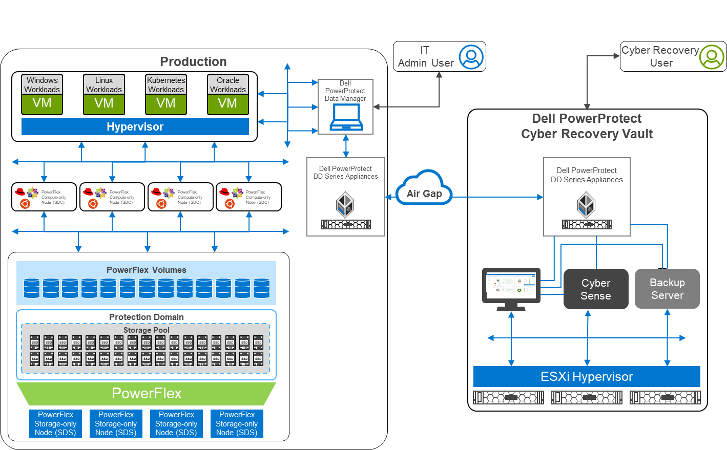
Figure 1: Architectural diagram
Air gaps and keeping the kingdom secure
The white paper describes a two-layer PowerFlex design in which the storage and compute environment are separate. The left side of the diagram shows the production environment. On the right side of the diagram, notice that there is a second environment, the Dell PowerProtect Cyber Recovery vault. The Cyber Recovery vault is a separate, logically air-gapped environment that helps to protect the production environment. The PowerProtect software runs on the Cyber Recovery vault and analyzes data from the production environment for signs of tampering, such as encryption of volumes or a large number of deletions.
The logical air gap between the two environments is only opened to replicate data from the production environment to the Cyber Recovery vault. Also, the connection between the two environments is only activated from the Cyber Recovery vault. I like to think of this scenario as a moat surrounding a castle with a drawbridge. The only way to cross the moat is over the drawbridge. The drawbridge is controlled from the castle—a secure location that is hard to breach. Likewise, the air gap makes it very difficult for intruders.
Separation of powers
Notice that there are two different users shown in the diagram: an Admin User and a Cyber Recovery User. This difference is important because many attacks can originate within the organization either knowingly or unknowingly, such as a spear phishing attack that targets IT. The division of powers and responsibilities makes it more difficult for a bad actor to compromise both users and get the keys to the kingdom. Therefore, the bad actor has a nearly impossible challenge disrupting both the production environment and the Cyber Recovery environment.
Protecting the kingdom
Let’s take a deeper look at the logical architecture used in the white paper. The design uses a pair of PowerProtect DD systems in which the data resides for both the production and vault sites. Replication between the two PowerProtect DD systems occurs over the logically air-gapped connection. Think of this replication of data as materials moving across the drawbridge to the castle. Material can arrive at the castle only when the gate house lowers the drawbridge.
The Cyber Recovery software is responsible for the synchronization of data and locking specified data copies. This software acts like the guards at the gate of the castle: they raise and lower the drawbridge and only allow so many carts into the castle at one time.
A backup server runs the Cyber Recovery software. The backup server supports various options to meet specific needs. Think of the backup server as the troops in a castle: there are the guards at the gate, archers on the walls, and all the other resources and activities that keep the castle safe. The type of troops varies depending on the size of the castle and the threat landscape. This scenario is also true of the backup server.
The Cyber Recovery environment also includes the CyberSense software, which is responsible for detecting signs of corruption caused by ransomware and similar threats. It uses machine learning (ML) to analyze the backup copies stored in the vault PowerProtect DD to look for signs of corruption. CyberSense detects corruption with a confidence level of up to 99.5 percent. Think of CyberSense as the trusted advisor to the castle: alerting the appropriate teams when an attack is imminent and allowing the castle to defend against attacks.
Putting it all together
In the following animation, we see a high-level overview of how the environment operates under normal conditions, during a ransomware attack, and during recovery. It shows content being replicated into the Cyber Recovery vault from the PowerFlex environment. We then see a bad actor attempt to compromise the VMs in the PowerFlex environment. CyberSense detects the attack and notifies the Cyber Recovery administrators. The administrators can then work with the production team to secure and restore the environment, thwarting the bad actor and the attempt to hold the organization hostage.
Figure 2: Animation of a ransomware attack and recovery
Beyond describing the architecture of this solution, the white paper shows how to deploy and configure both environments. Readers can take the next step towards building protection from a cyberattack.
The white paper is an excellent resource to learn more about protecting your kingdom from ransomware. To choose “not to be” a ransomware victim, contact your Dell representative for additional information.
Author: Tony Foster
Twitter: @wonder_nerd
LinkedIn

Dell PowerFlex Bare Metal with Amazon Elastic Kubernetes Service Anywhere, and We Do Mean “Anywhere!”
Mon, 18 Jul 2022 15:52:39 -0000
|Read Time: 0 minutes
Anywhere, that’s a powerful statement, especially to someone who works in IT. That could be in a cloud, or in a set of virtual machines in your data center, or even physical hosts. What if you could run Amazon Elastic Kubernetes Service (EKS) Anywhere on a virtual machine or on bare-metal, anywhere, including your data center?
You might have read my previous blog where we discussed running Amazon EKS Anywhere on Dell PowerFlex in a virtual environment. This time we are going further and have validated Amazon EKS Anywhere on a bare-metal instance of PowerFlex.
The good old days
If you are old enough to remember, like I am, the days before virtualization, with stranded resources and data centers with enormous footprints to support all the discrete servers and siloed workloads, you might be curious: Why would anyone go back to bare-metal?
Having been part of the movement all the way back to 2006, it’s a good question. In simple terms, what we are seeing today is not a return to the bare-metal siloed data centers of 20 years ago. Instead, we are seeing an improved utilization of resources by leveraging micro services, be that in the cloud, in virtualized environments, or with bare-metal. In addition, it provides greater portability and scalability than could ever have been imagined 20 years ago. This is thanks to the use of containers and the way they isolate processes from each other. Additionally, with a bare-metal platform running containers, more system resources can be directed to workloads than if the containers were nested inside of a virtual environment.
This is central to the concept of a DevOps-ready platform. In the coming weeks, we will expand on how this enhances the productivity of native cloud operations for today’s modern businesses. You will find this on the Dell Digital blog with the title Customer Choice Comes First: Dell Technologies and AWS EKS Anywhere.
Beyond just the economics of this, there are scenarios where a bare-metal deployment can be helpful. This includes low latency and latency sensitive applications that need to run near the data origin. This of course can include edge scenarios where it is not practical to transmit vast quantities of data.
Data sovereignty and compliance can also be addressed as an Amazon EKS Anywhere solution. While data and associated processing can be done in the data center, to maintain compliance requirements, it can still be part of a holistic environment that is displayed in the Amazon EKS Console when the Amazon EKS Connector has been configured. This allows for monitoring of applications running anywhere in the environment.
Digging deeper
Digging deeper on this concept, PowerFlex is a software defined infrastructure (SDI) that provides a powerful tool in delivering the modern bare-metal or virtualized options that best suit application deployment needs. The hardware infrastructure becomes malleable to the needs of the data center and can take on various forms of modern infrastructure, from hyper-converged to bare-metal. This has always been a core tenet of PowerFlex.
When Amazon EKS Anywhere is deployed on PowerFlex, it becomes possible to optimize the IT environment precisely for the needs of the environment, instead of forcing it to conform to the limits of IT infrastructure. Bare-metal hosts can provide microservices for large applications, such as databases and websites, where a container instance may be created and destroyed rapidly and on a massive scale.
The architecture
Let’s look at the Amazon EKS Anywhere validated architecture in the following figure. It shows how PowerFlex delivers a unique software-defined 3-tier architecture that can asymmetrically scale compute separate from storage.
The bottom portion of the figure consists of PowerFlex – storage-only nodes (1U). In the middle of the diagram are the hosts used for the control plane and worker nodes. These are PowerFlex – compute-only nodes (2U). On the far left are the admin and Tinkerbell nodes that allow for administration of the environment. Lastly, in the top set of boxes, we have the control plane, at the top left, that provides operational control and orchestration. The worker nodes, at the top right, handle the workloads.
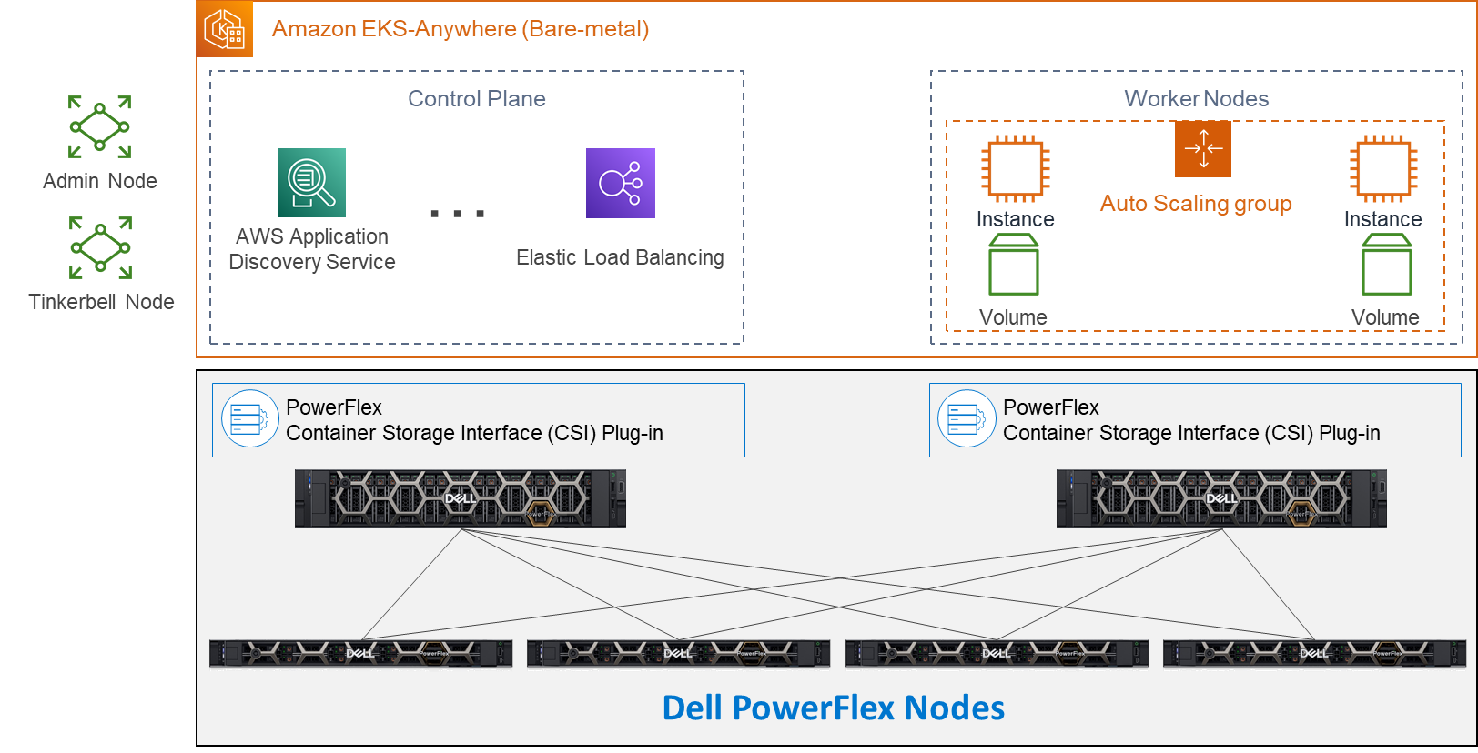
Let’s look at some important aspects of each area shown here, starting with the storage nodes. Each storage node contains five 1.4TB SAS SSD drives and eight 25GbE network links. For the validation, as shown here, four PowerFlex storage nodes were used to provide full redundancy.
For the compute nodes, we used two 2U nodes. These two hosts have the PowerFlex Container Storage Interface (CSI) Plug-in installed to provide access to the PowerFlex storage. This is deployed as part of the PXE boot process along with the Ubuntu OS. It’s important to note that there is no hypervisor installed and that the storage is provided by the four storage nodes. This creates a two-layer architecture which, as you can see, creates separate storage and compute layers for the environment.
Using a two-layer architecture makes it possible to scale resources independently as needed in the environment, which allows for optimal resource utilization. Thus, if more storage is needed, it can be scaled without increasing the amount of compute. And likewise, if the environment needs additional compute capacity, it can easily be added.
Cluster Creation
Outside of the Amazon EKS Anywhere instance are two nodes. Both are central to building the control plane and worker nodes. The admin node is where the user can control the Amazon EKS Anywhere instance and serves as a portal to upload inventory information to the Tinkerbell node. The Tinkerbell node serves as the infrastructure services stack and is key in the provisioning and PXE booting of the bare-metal workloads.
When a configuration file with the data center hardware has been uploaded, Tinkerbell generates a cluster configuration file. The hardware configuration and cluster configuration files, both in YAML format, are processed by Tinkerbell to create a boot strap kind cluster on the admin host to install the Cluster-API (CAPI) and the Cluster-API-Provider-Tinkerbell (CAPT).
With the base control environment operational, CAPI creates cluster node resources, and CAPT maps and powers on the corresponding bare-mental servers. The bare-metal servers PXE boot from the Tinkerbell node. The bare-metal servers then join the Kubernetes cluster. Cluster management resources are transferred from the bootstrap cluster to the target Amazon EKS Anywhere workload cluster. The local bootstrap kind cluster is then deleted from the admin machine. This creates both the Control Plane and Worker Nodes. With the cluster established, SDC drivers are installed on the Worker node(s) along with the Dell CSI Plug-in for PowerFlex. At this point, workloads can be deployed to the Worker node(s) as needed.
Cluster Provisioning
With the infrastructure deployed, our solutions engineers were able to test the Amazon EKS Anywhere environment. The testing included provisioning persistent volume claims (PVCs), expanding PVCs, and snapshotting them. All of this functionality relies on the Dell CSI Plugin for PowerFlex. Following this validation, a test workload can be deployed on the bare-metal Amazon EKS Anywhere environment.
If you would like to explore the deployment further, the Dell Solutions Engineering team is creating a white paper on the deployment of Amazon EKS Anywhere that covers these details in greater depth. When published, we will be sure to update this blog with a link to the white paper.
Anywhere
This validation enables the use of Amazon EKS Anywhere across bare-metal environments, expanding the use beyond the previous validation of virtual environments. This means that you can use Amazon EKS Anywhere anywhere, really!
With bare-metal deployments, it is possible to scale environments independently based on resource demands. PowerFlex software defined infrastructure not only supports a malleable environment like this, but also allows mixing environments to include hyper converged components. This means that an infrastructure can be tailored to the environment’s needs — instead of the environment being forced to conform to the infrastructure. It also creates an environment that unifies the competing demands of data sovereignty and cloud IT, by enabling data to maintain appropriate residence while unifying the control plane.
If you’re interested in finding out more about how you can leverage Amazon EKS Anywhere in your bare-metal PowerFlex environment, reach out to your Dell representative. Where is anywhere for you?
Resources
- Deploying a test workload
- Amazon Elastic Kubernetes Service Anywhere on Dell PowerFlex
- Introducing bare metal deployments for Amazon EKS Anywhere
- Blog: Customer Choice Comes First: Dell Technologies and AWS EKS Anywhere
Authors: Tony Foster
Twitter: @wonder_nerd
LinkedIn
Syed Abrar LinkedIn

How PowerFlex Transforms Big Data with VMware Greenplum
Tue, 01 Nov 2022 21:18:15 -0000
|Read Time: 0 minutes
Quick! The word has just come down. There is a new initiative that requires a massively parallel processing (MPP) database, and you are in charge of implementing it. What are you going to do? Luckily, you know the answer. You also just discovered that the Dell PowerFlex Solutions team has you covered with a solutions guide for VMware Greenplum.
What is in the solutions guide and how will it help with an MPP database? This blog provides the answer. We look at what Greenplum is and how to leverage Dell PowerFlex for both the storage and compute resources in Greenplum.
Infrastructure flexibility: PowerFlex
If you have read my other blogs or are familiar with PowerFlex, you know it has powerful transmorphic properties. For example, PowerFlex nodes sometimes function as both storage and compute, like hyperconverged infrastructure (HCI). At other times, PowerFlex functions as a storage-only (SO) node or a compute-only (CO) node. Even more interesting, these node types can be mixed and matched in the same environment to meet the needs of the organization and the workloads that they run.
This transmorphic property of PowerFlex is helpful in a Greenplum deployment, especially with the configuration described in the solutions guide. Because the deployment is built on open-source PostgreSQL, it is optimized for the needs of an MPP database, like Greenplum. PowerFlex can deliver the compute performance necessary to support massive data IO with its CO nodes. The PowerFlex infrastructure can also support workloads running on CO nodes or nodes that combine compute and storage (hybrid nodes). By leveraging the malleable nature of PowerFlex, no additional silos are needed in the data center, and it may even help remove existing ones.
The architecture used in the solutions guide consists of 12 CO nodes and 10 SO nodes. The CO nodes have VMware ESXi installed on them, with Greenplum instances deployed on top. There are 10 segments and one director deployed for the Greenplum environment. The 12th CO node is used for redundancy.
The storage tier uses the 10 SO nodes to deliver 12 volumes backed by SSDs. This configuration creates a high speed, highly redundant storage system that is needed for Greenplum. Also, two protection domains are used to provide both primary and mirror storage for the Greenplum instances. Greenplum mirrors the volumes between those protection domains, adding an additional level of protection to the environment, as shown in the following figure:
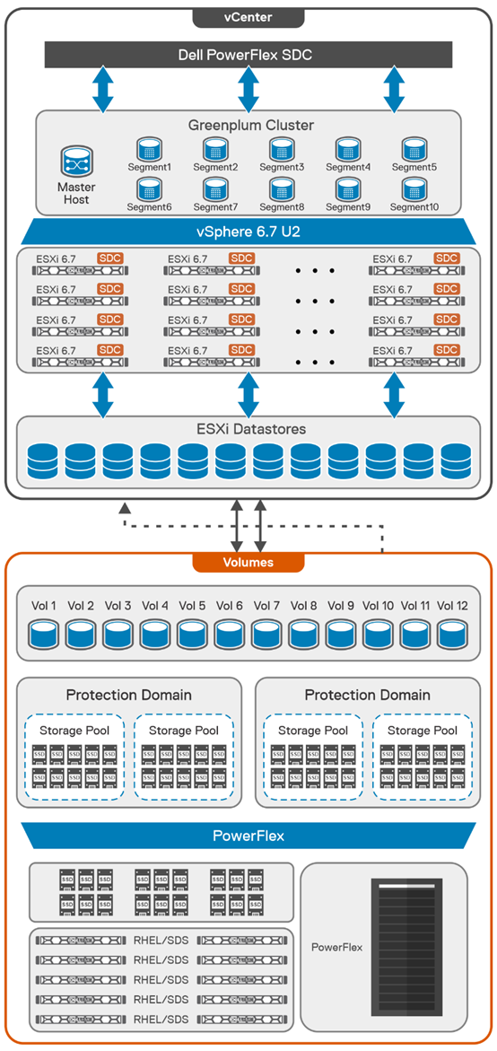
By using this fluid and composable architecture, the components can be scaled independently of one another, allowing for storage to be increased either independently or together with compute. Administrators can use this configuration to optimize usage and deliver appropriate resources as needed without creating silos in the environment.
Testing and validation with Greenplum: we have you covered
The solutions guide not only describes how to build a Greenplum environment, it also addresses testing, which many administrators want to perform before they finish a build. The guide covers performing basic validations with FIO and gpcheckperf. In the simplest terms, these tools ensure that IO, memory, and network performance are acceptable. The FIO tests that were run for the guide showed that the HBA was fully saturated, maximizing both read and write operations. The gpcheckperf testing showed a performance of 14,283.62 MB/sec for write workloads.
Wouldn’t you feel better if a Greenplum environment was tested with a real-world dataset? That is, taking it beyond just the minimum, maximum, and average numbers? The great news is that the architecture was tested that way! Our Dell Digital team has developed an internal test suite running static benchmarked data. This test suite is used at Dell Technologies across new Greenplum environments as the gold standard for new deployments.
In this test design, all the datasets and queries are static. This scenario allows for a consistent measurement of the environment from one run to the next. It also provides a baseline of an environment that can be used over time to see how its performance has changed -- for example, if the environment sped up or slowed down following a software update.
Massive performance with real data
So how did the architecture fare? It did very well! When 182 parallel complex queries were run simultaneously to stress the system, it took just under 12 minutes for the test to run. In that time, the environment had a read bandwidth of 40 GB/s and a write bandwidth of 10 GB/s. These results are using actual production-based queries from the Dell Digital team workload. These results are close to saturating the network bandwidth for the environment, which indicates that there are no storage bottlenecks.
The design covered in this solution guide goes beyond simply verifying that the environment can handle the workload; it also shows how the configuration can maintain performance during ongoing operations.
Maintaining performance with snapshots
One of the key areas that we tested was the impact of snapshots on performance. Snapshots are a frequent operation in data centers and are used to create test copies of data as well as a source for backups. For this reason, consider the impact of snapshots on MPP databases when looking at an environment, not just how fast the database performs when it is first deployed.
In our testing, we used the native snapshot capabilities of PowerFlex to measure the impact that snapshots have on performance. Using PowerFlex snapshots provides significant flexibility in data protection and cloning operations that are commonly performed in data centers.
We found that when the first storage-consistent snapshot of the database volumes was taken, the test took 45 seconds longer to complete than initial tests. This result was because it was the first snapshot of the volumes. Follow-on snapshots during testing resulted in minimal impact to the environment. This minimal impact is significant for MPP databases in which performance is important. (Of course, performance can vary with each deployment.)
We hope that these findings help administrators who are building a Greenplum environment feel more at ease. You not only have a solution guide to refer to as you architect the environment, you can be confident that it was built on best-in-class infrastructure and validated using common testing tools and real-world queries.
The bottom line
Now that you know the assignment is coming to build an MPP database using VMware Greenplum -- are you up to the challenge?
If you are, be sure to read the solution guide. If you need additional guidance on building your Greenplum environment on PowerFlex, be sure to reach out to your Dell representative.
Resources
Authors:
- Tony Foster – Dell Technologies, Twitter: @wonder_nerd
LinkedIn - Sue Mosovich – VMware

Expanding VxRail Dynamic Node Storage Options with PowerFlex
Wed, 09 Feb 2022 19:53:55 -0000
|Read Time: 0 minutes
It was recently announced that Dell VxRail dynamic nodes now supports Dell PowerFlex. This announcement expands the storage possibilities for VxRail dynamic nodes, providing a powerful and complimentary option for hyperconverged data centers. A white paper published by the Dell Technologies Solutions Engineering team details this configuration with VxRail dynamic nodes and PowerFlex.
In this blog we will explore how to use VxRail dynamic nodes with PowerFlex and explain why the two in combination are beneficial for organizations. We will begin by providing an overview for the dynamic nodes and PowerFlex, then describe why this duo is beneficial, and finally we will look at some of the exciting aspects of the white paper.
VxRail dynamic nodes and PowerFlex
VxRail
VxRail dynamic nodes are compute-only nodes, meaning these nodes don’t provide vSAN storage. They are available in the E, P, and V Series and accommodate a large variety of use cases. VxRail dynamic nodes rely on an external storage resource as their primary storage, which in this case is PowerFlex.
The following diagram shows a traditional VxRail environment is on the left. This environment uses VMware vSAN datastore for storage. The right side of the diagram is a VxRail dynamic node cluster. The VxRail dynamic nodes are compute only nodes, and, in this case rely on PowerFlex for storage. In this diagram the VxRail cluster, the VxRail dynamic node cluster, and the PowerFlex storage can all be scaled independently of one another for certain workloads. For example, some may want to adjust resources for Oracle environments to reduce license costs.
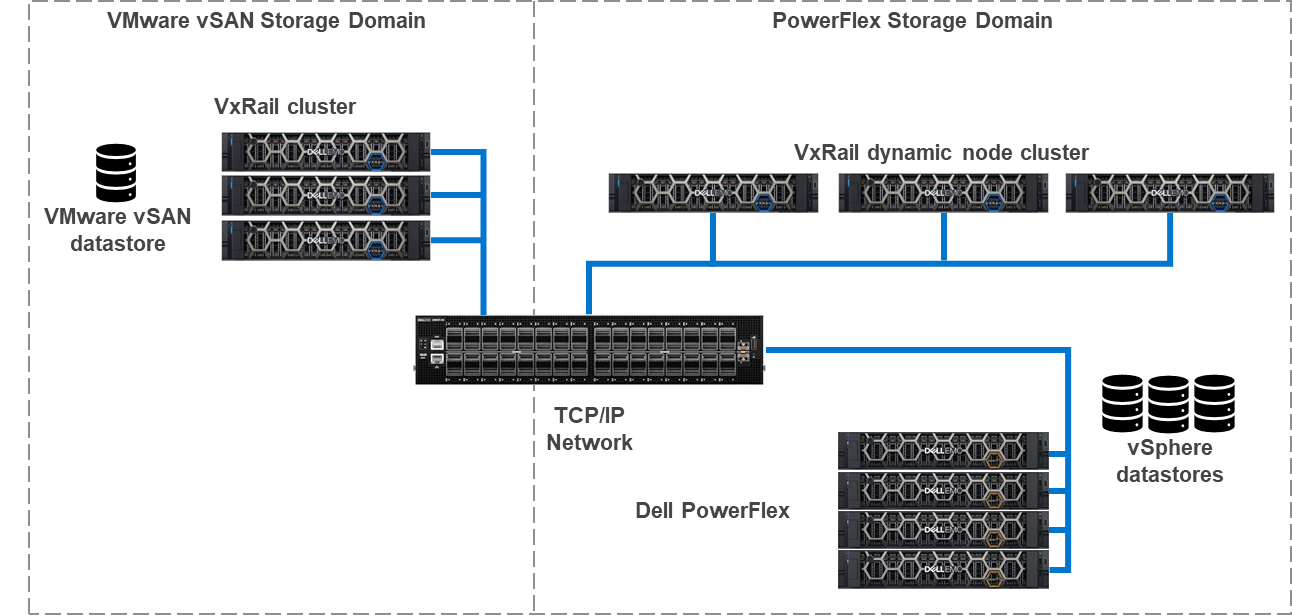
To learn more about VxRail dynamic nodes, see my colleague Daniel Chiu’s blog on the VxRail 7.0.240 release.
PowerFlex
PowerFlex is a software defined infrastructure that delivers linear scaling of performance and resources. PowerFlex is built on top of PowerEdge servers and aggregates the storage of four or more PowerFlex nodes to create a high-performance software defined storage system. PowerFlex uses a traditional TCP/IP network to connect nodes and deliver storage to environments. This is the only storage platform for VxRail dynamic nodes that uses an IP network. Both of these attributes are analogous to how VxRail delivers storage.
PowerFlex-VxRail benefits
If it seems confusing because VxRail and PowerFlex seem to share many of the same characteristics, it is they do share many of the same characteristics. However, this is why it also makes sense to bring them together. This section of this blog describes how the two can be combined to deliver a powerful architecture for certain applications.
The following diagram shows the logical configuration of PowerFlex and VxRail combined. Starting at the top of the diagram, you will see the VxRail cluster, consisting of four dynamic nodes. These dynamic nodes are running the PowerFlex Storage Data Client (SDC), a software-based storage adapter, which runs in the ESXi kernel. The SDC enables the VxRail dynamic nodes to consume volumes provisioned from the storage on the PowerFlex nodes.
In the lower half of the diagram, we see the PowerFlex nodes and the storage they present. The cluster contains four PowerFlex storage-only nodes. In these nodes, the internal drives are aggregated into a storage pool that spans across all four nodes. The storage pool capacity can then be provisioned as PowerFlex volumes to the VxRail dynamic nodes.
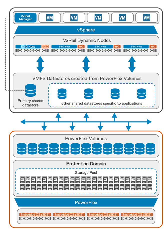
AI workloads offer a great example of where it makes perfect sense to bring these two technologies together. There has been a lot of buzz around virtualizing AI, ML, and HPC workloads. Dell, NVIDIA, and VMware have done amazing things in this area, including NVIDIA AI Enterprise on VxRail. Now you may think this does not matter to your organization, as there are no uses for AI, ML, or HPC in your organizations, but uses for AI are constantly evolving. For example, AI is even being used extensively in agriculture.
These new AI technologies are data driven and require massive amounts of data to train and validate models. This data needs to be stored somewhere, and the systems processing benefit from quick access to it and VxRail is awesome for that. There are exceptions, what if your data set is too large for VxRail, or what if you have multiple AI models that need to be shared amongst multiple clusters?
The typical response in this scenario is to get a storage array for the environment. That would work, except you’ve just added complexity to the environment. Many users move to HCI to drive complexity out of their environment. Fibre channel is a great example of this complexity.
To reduce complexity, there’s another option, just use PowerFlex. PowerFlex can support hundreds of nodes, enabling highly-performant storage needed for modern, data hungry applications. Additionally, it operates on standard TCP/IP networks, eliminating the need for a dedicated storage switch fabric. This makes it an ideal choice for virtualized AI workloads.
The idea of a standard network may be important to some organizations, due to the complexity aspects or they may not have the in-house talent to administer a Fibre channel network. This is particularly true in areas where administrators are hard to find. Leveraging the skills and resources already available within an organization, now more than ever, is extremely important.
Another area where PowerFlex backed VxRail dynamic nodes can be beneficial is with data services like data at rest encryption (D@RE). Both vSAN and PowerFlex support D@RE technology. When encryption is run on a host, the encryption/decryption process consumes resources. This impact can vary depending on the workload. If the workload has a lot of I/O, the resource utilization (CPU and RAM) could be more than a workload with lower I/O. When D@RE is offloaded, those resources needed for D@RE can be used for other tasks, such as workloads.
Beyond D@RE, PowerFlex has many other built in data resiliency and protection mechanisms. These include a distributed mesh mirroring system and native asynchronous replication. These functions help deliver fast data access and a consistent data protection strategy.
The impact of storage processing, like encryption, can impact the number of hosts that need to be licensed. Good examples of this are large databases with millions of transactions per minute (TPM). For each data write there is an encryption process. This process can be small and appear inconsequential, that is until you have millions of those processes happening in the same time span. This can cause a performance degradation if there aren’t enough resources to handle both the encryption processing and the CPU/RAM demands of the database environment and can lead to needing additional hosts to support the database environment.
In such a scenario, it can be advantageous to use VxRail dynamic nodes with PowerFlex. This offloads the encryption to PowerFlex allowing all the compute performance to be delivered to the VMs.
Dell PowerFlex with VxRail Dynamic Nodes – White Paper
The Solutions Engineering team has included many graphics detailing both the logical and physical design of how VxRail dynamic nodes can be configured with PowerFlex.
It highlights several important prerequisites, including that you will need to be using VxRail system software version 7.0.300 or above. This is important as this release is when support for PowerFlex was added to VxRail dynamic nodes. If the VxRail environment is not at the correct version, it could cause delays while the environment is upgraded to a compatible version.
Beyond just building an environment, the white paper also details administrating the environment. While administration is a relatively straight forward for seasoned administrators, it’s always good to have instructions in case an administrator is sick or other members of the team are gaining experience.
All of this and so much more are outlined in the white paper. If you are interested in all the details, be sure to read through it. This applies if your team is currently using VxRail and looking to add dynamic nodes or if you have both PowerFlex and VxRail in your environment and you want to expand the capabilities of each.
Summary
This blog provided an overview of VxRail dynamic nodes and how they can take advantage of PowerFlex software defined storage when needed. This includes reducing licensing costs and keeping complexity, like fiber channel, to a minimum in your environment. To find out more, read the white paper or talk with your Dell representative.
Author Information
Author: Tony Foster
Twitter: @wonder_nerd

PowerFlex and Amazon: Destination EKS Anywhere
Wed, 19 Jan 2022 17:09:54 -0000
|Read Time: 0 minutes
Welcome to your destination. Today Dell Technologies is pleased to share that Amazon Elastic Kubernetes Service (Amazon EKS) Anywhere has been validated on Dell PowerFlex software-defined infrastructure. Amazon EKS Anywhere is a new deployment option for Amazon EKS that enables customers to easily create and operate Kubernetes clusters on-premises while allowing for easy connectivity and portability to Amazon AWS environments. PowerFlex helps customers deliver a flexible deployment solution that scales as needs change with smooth, painless node-by-node expandability, inclusive of compute and storage, in a unified fabric architecture.
Dell Technologies collaborates with a broad ecosystem of public cloud providers to help our customers support multi-cloud environments that help place the right data and applications where it makes the most sense for them. Deploying Amazon EKS Anywhere on Dell Technologies infrastructure streamlines application development and delivery by allowing organizations to easily create and manage on premises Kubernetes clusters.
Across nearly all industries, IT organizations are moving to a more developer-oriented model that requires automated processes, rapid resource delivery, and reliable infrastructure. To drive operational simplicity through Kubernetes orchestration, Amazon EKS Anywhere helps customers automate cluster management, reduce support costs, and eliminate the redundant effort of using multiple open source or 3rd party tools to manage Kubernetes clusters. The combination of automated Kubernetes cluster management with intelligent, automated infrastructure quickly brings organizations to the next stop in their IT Journey, allowing them to provide infrastructure as code and empower their DevOps teams to be the innovation engine for their businesses.
Let us explore Amazon EKS Anywhere on PowerFlex and how it helps you move towards a more developer-oriented model. First, let’s look at the requirements for Amazon EKS Anywhere.
To deploy Amazon EKS Anywhere we will need a PowerFlex environment running VMware vSphere 7.0 or higher. Specifically, our validation used vSphere 7.0.2. We will also need to ensure we have sufficient capacity to deploy 8 to 10 Amazon EKS VMs. Additionally, we will need a network in the vSphere workload cluster with a DHCP service. This network is what the workload VMs will connect to. There are also a few Internet locations that the Amazon EKS administrative VM will need to reach, so that the manifests, OVAs, and Amazon EKS distro can be downloaded. Initial deployments can start with as few as four PowerFlex nodes and grow to meet the expansion needs of storage, compute, or both for scalability of over 1,000 nodes.
The logical view of the Amazon EKS Anywhere environment on PowerFlex is illustrated below. 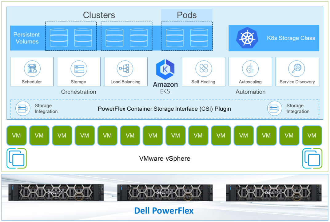
There are two types of templates used for the workloads: a Bottlerocket template and an Ubuntu image. The Bottlerocket template is a customized image from Amazon that is specific to Amazon EKS Anywhere. The Ubuntu template was used for our validation.
Note: Bottlerocket is a Linux-based open-source operating system that is purpose-built by Amazon. It focuses on security and maintainability, and provides a reliable, consistent, and safe platform for container-based workloads. Amazon EKS managed node groups with Bottlerocket support enable you to leverage the simplicity of managed node provisioning and lifecycle management features, while using the latest best practices for running containers in production. You can run your Kubernetes workloads on Bottlerocket nodes and benefit from enhanced security, higher cluster utilization, and less operational overhead. https://aws.amazon.com/blogs/containers/amazon-eks-adds-native-support-for-bottlerocket-in-managed-node-groups/
After the Amazon EKS admin VM is deployed, a command is issued on the Amazon EKS admin VM. This deploys the workload clusters and creates associated CRD instances on the workload cluster. This illustrates the ease of container deployment with Amazon EKS Anywhere. A single instance was prepped, then with some built-in scripting and commands, the system can direct the complex deployment. This greatly simplifies the process when compared to a traditional Kubernetes deployment.
At this point, the deployment can be tested. Amazon provides a test workload that can be used to validate the environment. You can find the details on testing on the Amazon EKS Anywhere documentation site.
The design that was validated was more versatile than a typical Amazon EKS Anywhere deployment. Instead of using the standard VMware CNS-CSI storage provider, this PowerFlex validation uses the Dell PowerFlex CSI plugin. This makes it possible to take direct advantage of PowerFlex’s storage capabilities. With the CSI plugin, it is possible to extend volumes through Amazon EKS, as well as snapshot and restore volumes.
This allows IT departments to move toward developer-oriented processes. Developers can work with storage natively. There are no additional tools to learn and no need to perform operations outside the development environment. This can be a time savings benefit to developer-oriented IT departments.
Beyond storage control in Amazon EKS Anywhere, the results of these operations can be viewed in the PowerFlex management interface. This provides an end-to-end view of the environment and allows traditional IT administrators to use familiar tools to manage and monitor their environment. This makes it easy for the entire IT organization’s journey to move towards a more developer centric environment.
By leveraging Amazon EKS Anywhere on PowerFlex, organizations get on-premises Kubernetes operational tooling that’s consistent with Amazon EKS. Organizations are able to leverage the Amazon EKS console to view all of their Kubernetes clusters (including Amazon EKS Anywhere clusters) running anywhere, through the Amazon EKS Connector. This brings together both the data center and cloud, simplifying the management of both.
In this journey, we have seen that Amazon EKS Anywhere has been validated on Dell PowerFlex, shown how they work together, and enable expanded storage capabilities for developers inside of Amazon EKS Anywhere. It also allows you to use familiar tools in managing the environment. To find out more about Amazon EKS anywhere on PowerFlex, talk with your Dell representative.
Author: Tony Foster, Sr. Technical Marketing Engineer
Twitter: @wonder_nerd LinkedIn

Deploying Microsoft SQL Server Big Data Clusters on Kubernetes platform using PowerFlex
Wed, 15 Dec 2021 12:20:15 -0000
|Read Time: 0 minutes
Introduction
Microsoft SQL Server 2019 introduced a groundbreaking data platform with SQL Server 2019 Big Data Clusters (BDC). Microsoft SQL Server Big Data Clusters are designed to solve the big data challenge faced by most organizations today. You can use SQL Server BDC to organize and analyze large volumes of data, you can also combine high value relational data with big data. This blog post describes the deployment of SQL Server BDC on a Kubernetes platform using Dell EMC PowerFlex software-defined storage.
PowerFlex
Dell EMC PowerFlex (previously VxFlex OS) is the software foundation of PowerFlex software-defined storage. It is a unified compute storage and networking solution delivering scale-out block storage service that is designed to deliver flexibility, elasticity, and simplicity with predictable high performance and resiliency at scale.
The PowerFlex platform is available in multiple consumption options to help customers meet their project and data center requirements. PowerFlex appliance and PowerFlex rack provide customers comprehensive IT Operations Management (ITOM) and life cycle management (LCM) of the entire infrastructure stack in addition to sophisticated high-performance, scalable, resilient storage services. PowerFlex appliance and PowerFlex rack are the preferred and proactively marketed consumption options. PowerFlex is also available on VxFlex Ready Nodes for those customers who are interested in software-defined compliant hardware without the ITOM and LCM capabilities.
PowerFlex software-define storage with unified compute and networking offers flexibility of deployment architecture to help best meet the specific deployment and architectural requirements. PowerFlex can be deployed in a two-layer for asymmetrical scaling of compute and storage for “right-sizing capacities, single-layer (HCI), or in mixed architecture.
Microsoft SQL Server Big Data Clusters Overview
Microsoft SQL Server Big Data Clusters are designed to address big data challenges in a unique way, BDC solves many traditional challenges through building big-data and data-lake environments. You can query external data sources, store big data in HDFS managed by SQL Server, or query data from multiple external data sources using the cluster.
SQL Server Big Data Clusters is an additional feature of Microsoft SQL Server 2019. You can query external data sources, store big data in HDFS managed by SQL Server, or query data from multiple external data sources using the cluster.
For more information, see the Microsoft page SQL Server Big Data Clusters partners.
You can use SQL Server Big Data Clusters to deploy scalable clusters of SQL Server and Apache SparkTM and Hadoop Distributed File System (HDFS), as containers running on Kubernetes.
For an overview of Microsoft SQL Server 2019 Big Data Clusters, see Microsoft’s Introducing SQL Server Big Data Clusters and on GitHub, see Workshop: SQL Server Big Data Clusters - Architecture.
Deploying Kubernetes Platform on PowerFlex
For this test, PowerFlex 3.6.0 is built in a two-layer configuration with six Compute Only (CO) nodes and eight Storage Only (SO) nodes. We used PowerFlex Manager to automatically provision the PowerFlex cluster with CO nodes on VMware vSphere 7.0 U2, and SO nodes with Red Hat Enterprise Linux 8.2.
The following figure shows the logical architecture of SQL Server BDC on Kubernetes platform with PowerFlex.
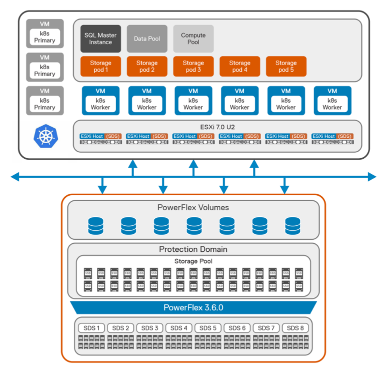
Figure 1: Logical architecture of SQL BDC on PowerFlex
From the storage perspective, we created a single protection domain from eight PowerFlex nodes for SQL BDC. Then we created a single storage pool using all the SSDs installed in each node that is a member of the protection domain.
After we deployed the PowerFlex cluster, we created eleven virtual machines on the six identical CO nodes with Ubuntu 20.04 on them, as shown in the following table.
Table 1: Virtual machines for CO nodes
Item | Node 1 | Node 2 | Node 3 | Node 4 | Node 5 | Node 6 |
Physical node | esxi70-1 | esxi70-2 | esxi70-3 | esxi70-4 | esxi70-5 | esxi70-6 |
H/W spec | 2 x Intel Gold 6242 R, 20 cores | 2 x Intel Gold 6242R, 20 cores | 2 x Intel Gold 6242R, 20 cores | 2 x Intel Gold 6242R, 20 cores | 2 x Intel Gold 6242R, 20 cores | 2 x Intel Gold 6242R, 20 cores |
Virtual machines | k8w1 | lb01 | lb02 | k8m1 | k8m2 | k8m3 |
k8w2 | k8w3 | k8w4 | k8w5 | k8w6 |
We manually installed the SDC component of PowerFlex on the worker nodes of Kubernetes. We then configured a Kubernetes cluster (v 1.20) on the virtual machines with three master nodes and eight worker nodes:
$ kubectl get nodes
NAME STATUS ROLES AGE VERSION
k8m1 Ready control-plane,master 10d v1.20.10
k8m2 Ready control-plane,master 10d v1.20.10
k8m3 Ready control-plane,master 10d v1.20.10
k8w1 Ready <none> 10d v1.20.10
k8w2 Ready <none> 10d v1.20.10
k8w3 Ready <none> 10d v1.20.10
k8w4 Ready <none> 10d v1.20.10
k8w5 Ready <none> 10d v1.20.10
k8w6 Ready <none> 10d v1.20.10
Dell EMC storage solutions provide CSI plugins that allow customers to deliver persistent storage for container-based applications at scale. The combination of the Kubernetes orchestration system and the Dell EMC PowerFlex CSI plugin enables easy provisioning of containers and persistent storage.
In the solution, after we installed the Kubernetes cluster, CSI 2.0 was provisioned to enable persistent volumes for SQL BDC workload.
For more information about PowerFlex CSI supported features, see Dell CSI Driver Documentation.
For more information about PowerFlex CSI installation using Helm charts, see PowerFlex CSI Documentation.
Deploying Microsoft SQL Server BDC on Kubernetes Platform
When the Kubernetes cluster with CSI is ready, Azure data CLI is installed on the client machine. To create base configuration files for deployment, see deploying Big Data Clusters on Kubernetes . For this solution, we used kubeadm-dev-test as the source for the configuration template.
Initially, using kubectl, each node is labelled to ensure that the pods start on the correct node:
$ kubectl label node k8w1 mssql-cluster=bdc mssql-resource=bdc-master --overwrite=true
$ kubectl label node k8w2 mssql-cluster=bdc mssql-resource=bdc-compute-pool --overwrite=true
$ kubectl label node k8w3 mssql-cluster=bdc mssql-resource=bdc-compute-pool --overwrite=true
$ kubectl label node k8w4 mssql-cluster=bdc mssql-resource=bdc-compute-pool --overwrite=true
$ kubectl label node k8w5 mssql-cluster=bdc mssql-resource=bdc-compute-pool --overwrite=true
$ kubectl label node k8w6 mssql-cluster=bdc mssql-resource=bdc-compute-pool --overwrite=true
To accelerate the deployment of BDC, we recommend that you use an offline installation method from a local private registry. While this means some extra work in creating and configuring a registry, it eliminates the network load of every BDC host pulling container images from the Microsoft repository. Instead, they are pulled once. On the host that acts as a private registry, install Docker and enable the Docker repository.
The BDC configuration is modified from the default settings to use cluster resources and address the workload requirements. For complete instructions about modifying these settings, see Customize deployments section in the Microsoft BDC website. To scale out the BDC resource pools, the number of replicas are adjusted to use the resources of the cluster.
The values shown in the following table are adjusted in the bdc.json file.
Table 2: Cluster resources
Resource | Replicas | Description |
nmnode-0 | 2 | Apache Knox Gateway |
sparkhead | 2 | Spark service resource configuration |
zookeeper | 3 | Keeps track of nodes within the cluster |
compute-0 | 1 | Compute Pool |
data-0 | 1 | Data Pool |
storage-0 | 5 | Storage Pool |
The configuration values for running Spark and Apache Hadoop YARN are also adjusted to the compute resources available per node. In this configuration, sizing is based on 768 GB of RAM and 72 virtual CPU cores available per PowerFlex CO node. Most of this configuration is estimated and adjusted based on the workload. In this scenario, we assumed that the worker nodes were dedicated to running Spark workloads. If the worker nodes are performing other operations or other workloads, you may need to adjust these values. You can also override Spark values as job parameters.
For further guidance about configuration settings for Apache Spark and Apache Hadoop in Big Data Clusters, see Configure Apache Spark & Apache Hadoop in the SQL Server BDC documentation section.
The following table highlights the spark settings that are used on the SQL Server BDC cluster.
Table 3: Spark settings
Settings | Value |
spark-defaults-conf.spark.executor.memoryOverhead | 484 |
yarn-site.yarn.nodemanager.resource.memory-mb | 440000 |
yarn-site.yarn.nodemanager.resource.cpu-vcores | 50 |
yarn-site.yarn.scheduler.maximum-allocation-mb | 54614 |
yarn-site.yarn.scheduler.maximum-allocation-vcores | 6 |
yarn-site.yarn.scheduler.capacity.maximum-am- resource-percent | 0.34 |
The SQL Server BDC 2019 CU12 release notes state that Kubernetes API 1.20 is supported. Therefore, for this test, the image that was deployed on the SQL master pod was 2019-CU12-ubuntu-16.04. A storage of 20 TB was provisioned for SQL master pod, with 10 TB as log space:
"nodeLabel": "bdc-master",
"storage": {
"data": {
"className": "vxflexos-xfs",
"accessMode": "ReadWriteOnce",
"size": "20Ti"
},
"logs": {
"className": "vxflexos-xfs",
"accessMode": "ReadWriteOnce",
"size": "10Ti"
}
}
Because the test involved running the TPC-DS workload, we provisioned a total of 60 TB of space for five storage pods:
"storage-0": {
"metadata": {
"kind": "Pool",
"name": "default"
},
"spec": {
"type": "Storage",
"replicas": 5,
"settings": {
"spark": {
"includeSpark": "true"
}
},
"nodeLabel": "bdc-compute-pool",
"storage": {
"data": {
"className": "vxflexos-xfs",
"accessMode": "ReadWriteOnce",
"size": "12Ti"
},
"logs": {
"className": "vxflexos-xfs",
"accessMode": "ReadWriteOnce",
"size": "4Ti"
}
}
}
}
Validating SQL Server BDC on PowerFlex
To validate the configuration of the Big Data Cluster that is running on PowerFlex and to test its scalability, we ran the TPC-DS workload on the cluster using the Databricks® TPC-DS Spark SQL kit. The toolkit allows you to submit an entire TPC-DS workload as a Spark job that generates the test dataset and runs a series of analytics queries across it. Because this workload runs entirely inside the storage pool of the SQL Server Big Data Cluster, the environment was scaled to run the recommended maximum of five storage pods.
We assigned one storage pod to each worker node in the Kubernetes environment as shown in the following figure.
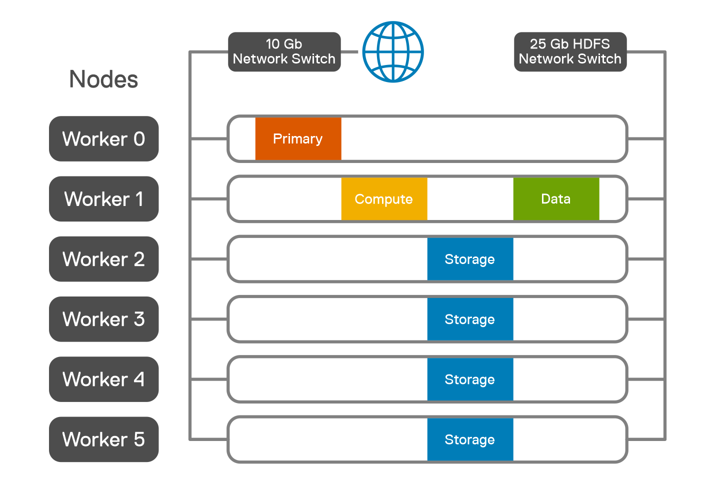
Figure 2: Pod placement across worker nodes
In this solution, Spark SQL TPC-DS workload is adopted to simulate a database environment that models several applicable aspects of a decision support system, including queries and data maintenance. Characterized by high CPU and I/O load, a decision support workload places a load on the SQL Server BDC cluster configuration to extract maximum operational efficiencies in areas of CPU, memory, and I/O utilization. The standard result is measured by the query response time and the query throughput.
A Spark JAR file is uploaded into a specified directory in HDFS, for example, /tpcds. The spark-submit is done by CURL, which uses the Livy server that is part of Microsoft SQL Server Big Data Cluster.
Using the Databricks TPC-DS Spark SQL kit, the workload is run as Spark jobs for the 1 TB, 5 TB, 10 TB, and 30 TB workloads. For each workload, only the size of the dataset is changed.
The parameters used for each job are specified in the following table.
Table 4: Job parameters
Parameter | Value |
spark-defaults-conf.spark.driver.cores | 4 |
spark-defaults-conf.spark.driver.memory | 8 G |
spark-defaults-conf.spark.driver.memoryOverhead | 484 |
spark-defaults-conf.spark.driver.maxResultSize | 16 g |
spark-defaults-conf.spark.executor.instances | 12 |
spark-defaults-conf.spark.executor.cores | 4 |
spark-defaults-conf.spark.executor.memory | 36768 m |
spark-defaults-conf.spark.executor.memoryOverhead | 384 |
spark.sql.sortMergeJoinExec.buffer.in.memory.threshold | 10000000 |
spark.sql.sortMergeJoinExec.buffer.spill.threshold | 60000000 |
spark.shuffle.spill.numElementsForceSpillThreshold | 59000000 |
spark.sql.autoBroadcastJoinThreshold | 20971520 |
spark-defaults-conf.spark.sql.cbo.enabled | True |
spark-defaults-conf.spark.sql.cbo.joinReorder.enabled | True |
yarn-site.yarn.nodemanager.resource.memory-mb | 440000 |
yarn-site.yarn.nodemanager.resource.cpu-vcores | 50 |
yarn-site.yarn.scheduler.maximum-allocation-mb | 54614 |
yarn-site.yarn.scheduler.maximum-allocation-vcores | 6 |
We set the TPC-DS dataset with the different scale factors in the CURL command. The data was populated directly into the HDFS storage pool of the SQL Server Big Data Cluster.
The following figure shows the time that is consumed for data generation of different scale factor settings. The data generation time also includes the post data analysis process that calculates the table statistics.
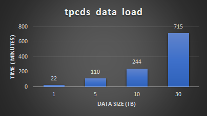
Figure 3: TPC-DS data generation
After the load we ran the TPC-DS workload to validate the Spark SQL performance and scalability with 99 predefined user queries. The queries are characterized with different user patterns.
The following figure shows the performance and scalability test results. The results demonstrate that running Microsoft SQL Server Big Data Cluster on PowerFlex has linear scalability for different datasets. This shows the ability of PowerFlex to provide a consistent and predictable performance for different types of Spark SQL workloads.
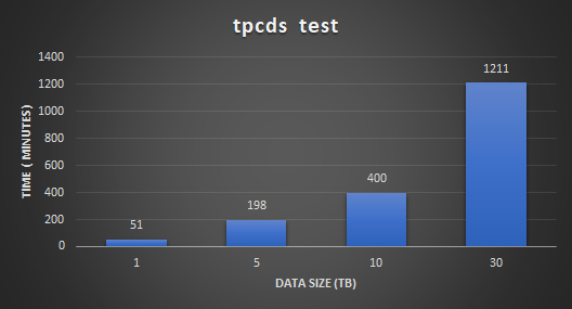
Figure 4: TPC-DS test results
A Grafana dashboard instance that is captured during the 30 TB run of TPC-DS test is shown in the following figure. The figure shows that the read bandwidth of 15 GB/s is achieved during the tests.
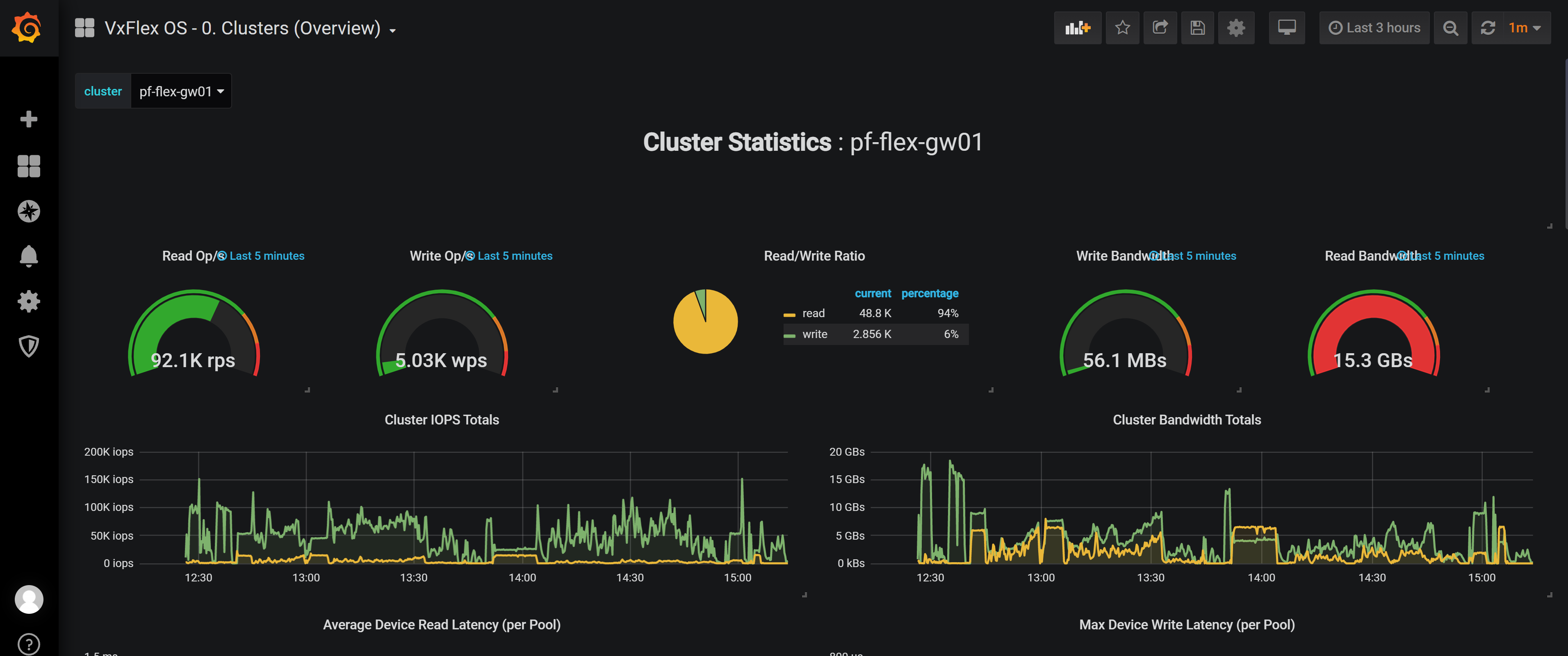
Figure 5: Grafana dashboard
In this minimal lab hardware, there were no storage bottlenecks for the TPC-DS data load and query execution. The CPU on the worker nodes reached close to 90 percent indicating that more powerful nodes could enhance the performance.
Conclusion
Running SQL Server Big Data Clusters on PowerFlex is a straightforward way to get started with modernized big data workloads running on Kubernetes. This solution allows you to run modern containerized workloads using the existing IT infrastructure and processes. Big Data Clusters allows Big Data scientists to innovate and build with the agility of Kubernetes, while IT administrators manage the secure workloads in their familiar vSphere environment.
In this solution, Microsoft SQL Server Big Data Clusters are deployed on PowerFlex which provides the simplified operation of servicing cloud native workloads and can scale without compromise. IT administrators can implement policies for namespaces and manage access and quota allocation for application focused management. Application-focused management helps you build a developer-ready infrastructure with enterprise-grade Kubernetes, which provides advanced governance, reliability, and security.
Microsoft SQL Server Big Data Clusters are also used with Spark SQL TPC-DS workloads with the optimized parameters. The test results show that Microsoft SQL Server Big Data Clusters deployed in a PowerFlex environment can provide a strong analytics platform for Big Data solutions in addition to data warehousing type operations.
For more information about PowerFlex, see Dell EMC PowerFlex. For more information about Microsoft SQL Server Big Data Clusters, see Introducing SQL Big Data Clusters.
If you want to discover more, contact your Dell representative.
References

The future of Cloud-Native infrastructure is Resilient and Flexible
Mon, 13 Dec 2021 18:40:31 -0000
|Read Time: 0 minutes
Next generation infrastructures to support Cloud-Native workloads must be resilient and flexible to satisfy workload requirements while also reducing the management burden on IT staffers.
While much of the emphasis on the benefits of Cloud-Native infrastructure are focused on speed and agility from development to deployment, the rise of stateful containerized applications will force organizations to take resiliency, storage performance and data services more seriously. In the Voice of the Enterprise: DevOps, Workloads & Projects 2020 study, 56% of organizations have more than 50% applications that are stateful and this trend will rise as more production workloads run on containers.
The need for persistent storage also raises the stakes for data protection capabilities such as snapshots, replication, backup and disaster recovery. Even when it comes to non-mission critical and non-business critical workloads such as test/dev, organizations have minimal tolerance for downtime or data loss. The rising customer expectations for resiliency will only increase pressure on organizations to implement storage systems with rich data protection capabilities and the ability to automate the deployment of these features based on the importance of a particular workload.
Data placement and optimization continue to be key concerns in large scale environments, and it is important for next generation systems to provide intelligent load balancing to position data across nodes in a manner that makes optimal use of resources. These data placement capabilities need to be automated, since many of these operations will occur in the background when workloads are not as active.
Though it is tempting to go with a clean sheet approach when designing next generation infrastructures for emerging Cloud-Native workloads, workloads that are branded as “legacy” do not disappear, even if they are not top of mind in planning discussions. In interactions with organizations building out Cloud-Native infrastructures, it is far more common for them to be running their containerized workloads on top of or inside of VMs today, as opposed to building a new silo of infrastructure for Cloud-Native.
Just as VMs have not completely displaced workloads running on non-virtualized physical systems, we are still a long way from seeing all of the applications currently running in VMs shifting over completely to containers. Infrastructures which have the flexibility to provide compute and storage resources for physical, virtualized, and containerized workloads simultaneously will be necessary for many years.
For more information, please read the 451 Research Special Report:
Infrastructure Requirements for a Cloud-Native World.
Author: Henry Baltazar
Copyright © 2021 S&P Global Market Intelligence.
The content of this artifact is for educational purposes only. 451 Research, S&P Global Market Intelligence does not endorse any companies, technologies, products, services, or solutions.

Increase Operational Efficiency with the Dell EMC PowerFlex App for Splunk
Tue, 04 Jul 2023 09:59:24 -0000
|Read Time: 0 minutes
In modern IT, admins struggle to manage and analyze enormous amounts of machine-generated data in order to understand its patterns and make important decisions. The Splunk Platform enables apps that can analyze and derive insights from data generated by disparate infrastructure layers, such as compute, storage, and network. The platform helps admins manage, visualize, analyze, and understand the various patterns efficiently and effectively to make the right decisions.
The Dell DMC PowerFlex software-defined platform is often used as an infrastructure foundation supporting multiple heterogeneous and SLA-sensitive workloads due to its scale-out nature and its ability to host workloads on a variety of hypervisors, containers, and bare metal platforms.
To support Splunk workloads, Dell Technologies offers the Dell EMC PowerFlex App for Splunk, integrating the PowerFlex environment with Splunk Enterprise. As a source for a vast amount of telemetry, the PowerFlex App for Splunk is a great tool for visualizing, monitoring, and capturing various PowerFlex storage metrics. It empowers the IT organizations to harness the power of data to improve IT outcomes by simplifying the storage management and operations.
Benefits to organizations
This app provides various benefits to organizations:
- Greater operational and storage efficiency
- Deeper storage environment insights
- Future capacity predictions
- Monitoring multiple storage environments from a single window
- Enhancing decision making capabilities based on historical trends
Key capabilities of the PowerFlex App for Splunk
Real-time visibility
24 out-of-the-box intuitive dashboards to visualize PowerFlex metrics in real-time. These metrics are logically grouped and presented in different dashboards.
Historical data
Historical data plays an important role in decision making. Taking decisive action before any event becomes a reality requires understanding the pattern over time. .
Health of the system
The app captures real time alerts at different levels, and they are categorized by severity.
Storage projection
This is one of the coolest features: using the native Splunk environment capabilities to forecast the future storage requirements based on the current usage.
Some sample dashboards
Overview Dashboard: Provides a summary of clusters and associated high level metrics, with navigation capabilities.
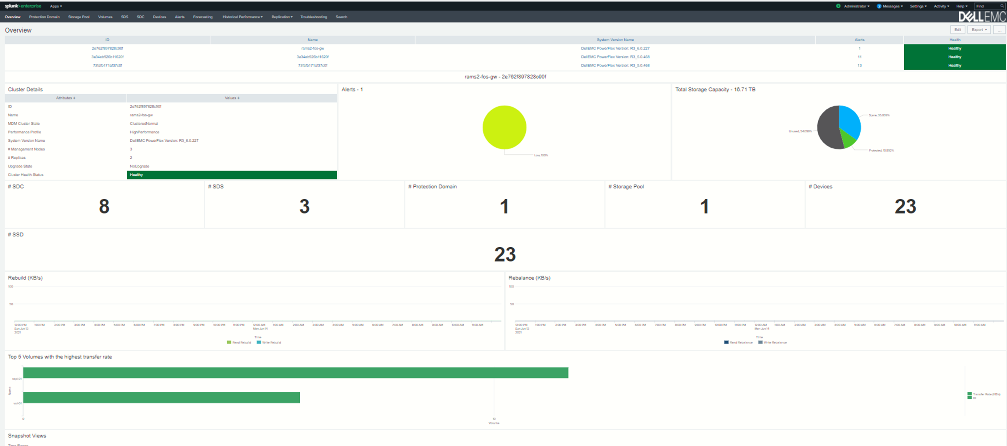
Replication Overview Dashboard: Provides a summary of Replication clusters and associated high level metrics.
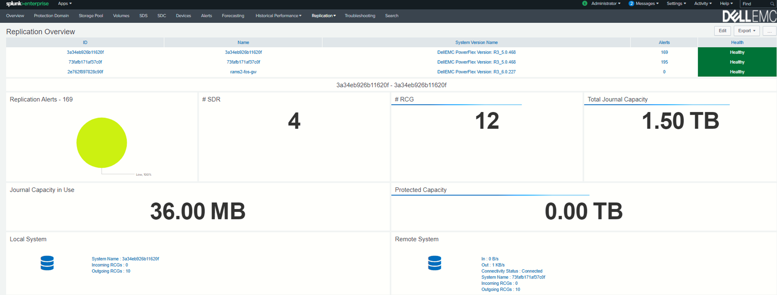
Storage Forecasting Dashboard: Provides the details of future storage requirements depending upon the current storage utilization.
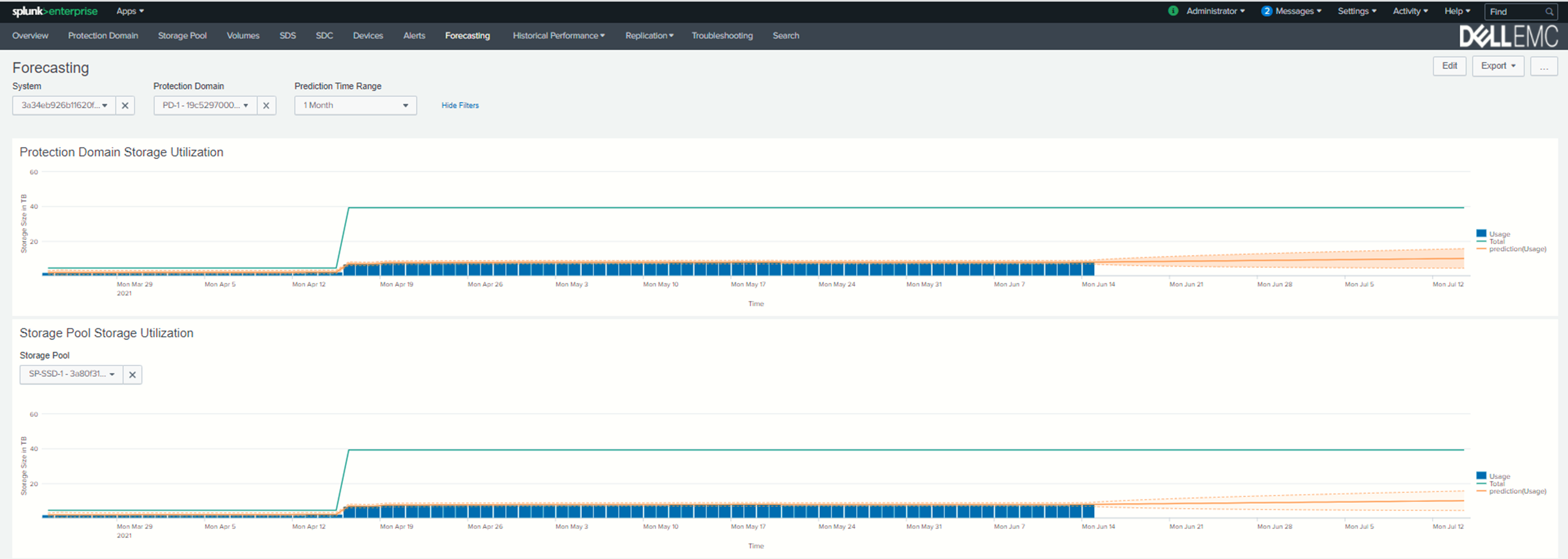
Historical Data Dashboard: Provides the historical performance data for the specified time intervals.
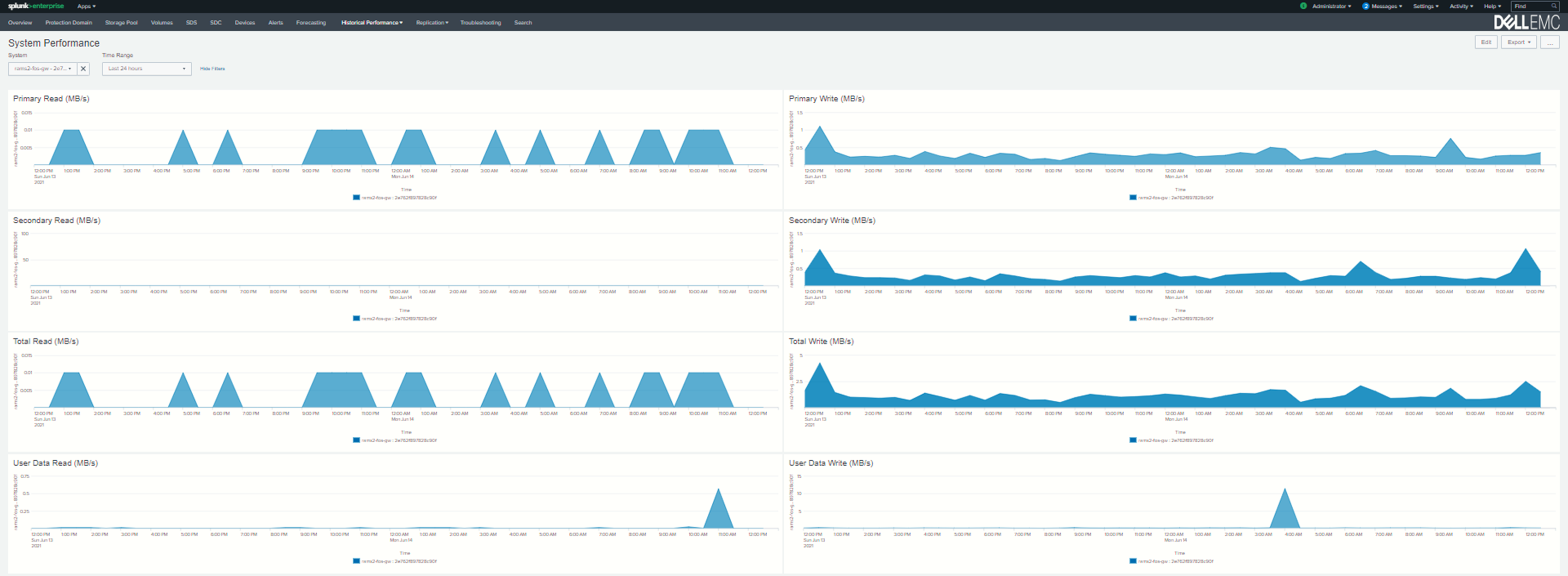
Related resources
PowerFlex App for Splunk infographic
Video: Dell EMC PowerFlex App for Splunk
Where to find Dell EMC PowerFlex App for Splunk
For those who are new to Splunk, you can get this app from http://splunkbase.splunk.com. This app comes in two parts:
- The Dell EMC PowerFlex App is available here https://splunkbase.splunk.com/app/5528/ and provides all the beautiful and awesome visualizations.
- The Add-on is available here https://splunkbase.splunk.com/app/5529/. This helps to configure the Gateways and to define the Instance End Points to make REST API calls.
Thanks for reading!
Author: Nataraj Naikar

Deploying Microsoft SQL Server Big Data Clusters on OpenShift platform using PowerFlex
Tue, 04 Jul 2023 09:51:15 -0000
|Read Time: 0 minutes
Introduction
Microsoft SQL Server 2019 introduced a groundbreaking data platform with SQL Server 2019 Big Data Clusters (BDC). SQL Server BDC are designed to solve the big data challenge faced by most organizations today. You can use SQL Server BDC to organize and analyze large volumes of data, you can also combine high value relational data with big data. In this blog, I will describe the deployment of Microsoft SQL Server BDC on an OpenShift container platform using Dell EMC PowerFlex software-defined storage.
PowerFlex
PowerFlex (previously VxFlex OS) is the software foundation of PowerFlex software-defined storage. It is a unified compute storage and networking solution delivering scale-out block storage service designed to deliver flexibility, elasticity, and simplicity with predictable high performance and resiliency at scale.
The PowerFlex platform is available in multiple consumption options to help customers meet their project and data center requirements. PowerFlex appliance and PowerFlex rack provide customers comprehensive IT Operations Management (ITOM) and life cycle management (LCM) of the entire infrastructure stack in addition to sophisticated high-performance, scalable, resilient storage services. PowerFlex appliance and PowerFlex rack are the two preferred and proactively marketed consumption options. PowerFlex is also available on VxFlex Ready Nodes for those customers interested in software-defined compliant hardware without the ITOM and LCM capabilities.
PowerFlex software-define storage with unified compute and networking offers flexibility of deployment architecture to help best meet the specific deployment and architectural requirements. PowerFlex can be deployed in a two-layer for asymmetrical scaling of compute and storage for “right-sizing capacities, single-layer (HCI), or in mixed architecture.
OpenShift Container Platform
Red Hat® OpenShift® Container Platform is a platform to deploy and create containerized applications. OpenShift Container Platform provides administrators and developers with the tools they require to deploy and manage applications and services at scale. OpenShift Container Platform offers enterprises full control over their Kubernetes environments, whether they are on-premises or in the public cloud, giving you the freedom to build and run applications anywhere.
Microsoft SQL Server Big Data Clusters Overview
Microsoft SQL Server Big Data Clusters are designed to address big data challenges in a unique way, BDC solves many traditional challenges faced in building big-data and data-lake environments. You can query external data sources, store big data in HDFS managed by SQL Server, or query data from multiple external data sources using the cluster. See an overview of Microsoft SQL Server 2019 Big Data Clusters on the Microsoft page Microsoft SQL Server BDC details and on the GitHub page SQL Server BDC Workshops.
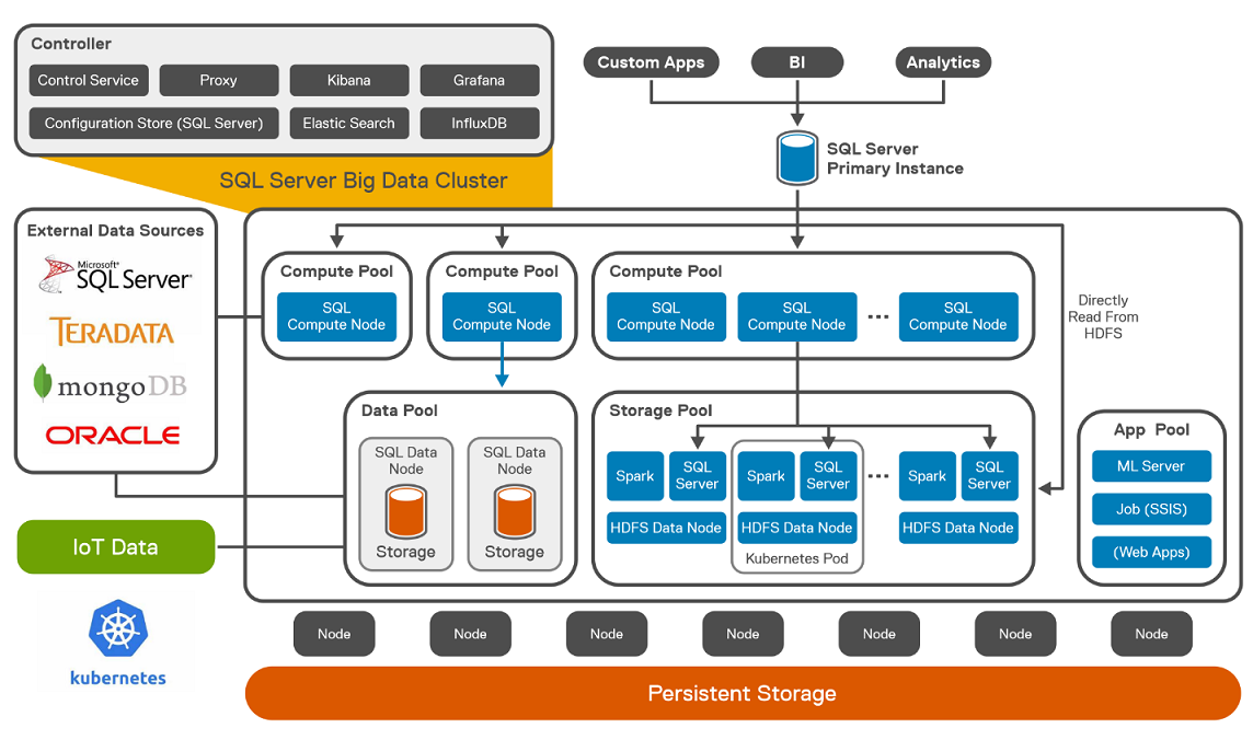 SQL Server Big Data Cluster components
Deploying OpenShift Container Platform on PowerFlex
The OpenShift cluster is configured with three master nodes and eight worker nodes. To install OpenShift Container Platform on PowerFlex, see OpenShift Installation.
The following figure shows the logical architecture of Red Hat OpenShift 4.6.x deployed on PowerFlex. The CSAH node is configured with the required services like DNS, DHCP, HTTP Server, and HA Proxy. It also hosts PowerFlex Gateway and PowerFlex GUI. 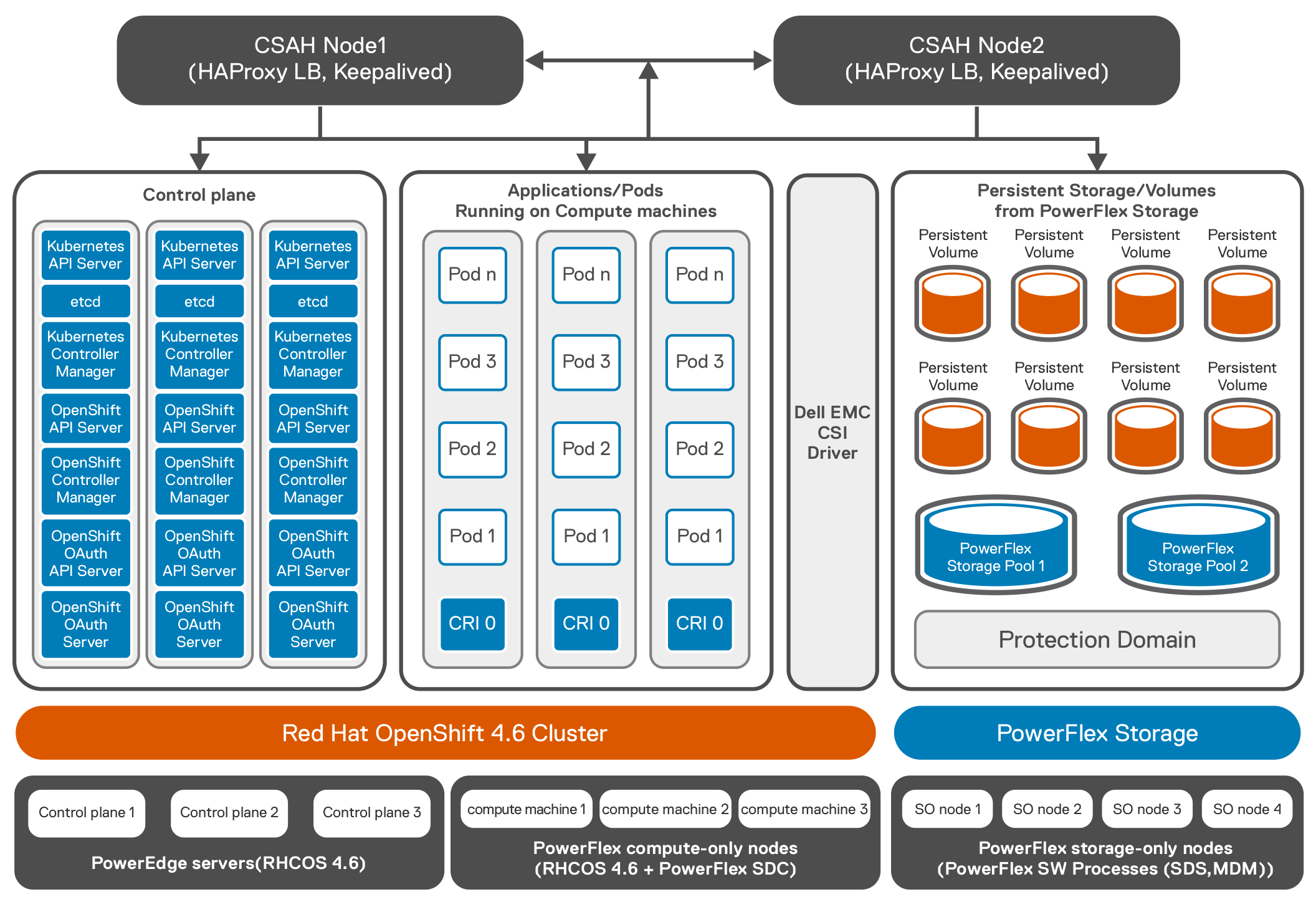 Logical architecture of Red Hat OpenShift 4.6.x deployed on PowerFlex
The following example shows OpenShift cluster with three master and eight worker nodes.
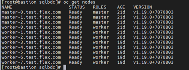
Once OpenShift installation is complete, CSI 1.4 is deployed on the OCP cluster. The CSI driver controller pod is deployed on one of the worker nodes and there are eight vxflexos-node pods that are deployed across eight worker nodes.
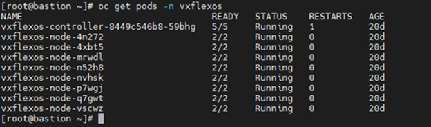
For more information about installation of CSI on OpenShift, see the GitHub page CSI installation.
Deploying Microsoft SQL Server BDC on OpenShift Container Platform
Microsoft SQL Server BDC cluster is deployed using OpenShift Container Platform as shown in the architecture diagram below by following instructions available at installation.
The following steps are performed to deploy Microsoft SQL Server BDC cluster using OpenShift Container Platform:
- The Azure Data CLI is installed on the client machine.
- All the pre-requisites for Microsoft SQL Server BDC on OpenShift cluster are performed. For this solution, openshift-prod was selected as the source for the configuration template from the list of available templates.
- All the OpenShift worker nodes are labeled before the Microsoft SQL Server BDC is installed.
- The control.json and bdc.json files are generated.
- The bdc.json is modified from the default settings to use cluster resources and to address the workload requirements. For example, the bdc.json looks like:
"spec": {
"type": "Master",
"replicas": 3,
"endpoints": [
{
"name": "Master",
"serviceType": "NodePort",
"port": 31433
},
{
"name": "MasterSecondary",
"serviceType": "NodePort",
"port": 31436
}
],
"settings": {
"sql": {
"hadr.enabled": "true"
}
},
……………
}
- The SQL image deployed in the control.json is 2019-CU9-ubuntu-16.04. To scale out the BDC resource pools, the number of replicas is adjusted to fully leverage the resources of the cluster. The following figure shows the logical architecture of Microsoft SQL Server BDC on OpenShift Container Platform with PowerFlex:7. SQL Server HA deployment is configured along with two data and two compute pods. Three storage pods are also configured. This type of configuration is used for TPC-C, and TPC-H like deployment as SQL is at HA mode with a single primary and couple of replicas. The following figure shows the pod placements across the eight worker nodes.
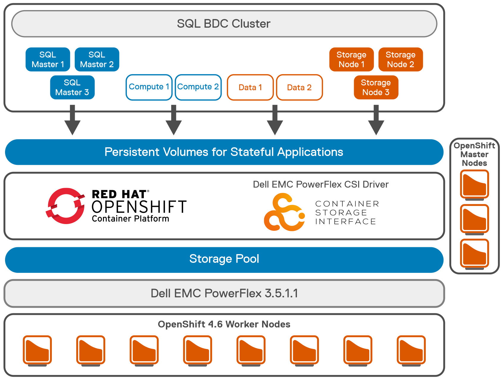 Logical architecture of Microsoft SQL Server BDC on OpenShift Container with PowerFlex
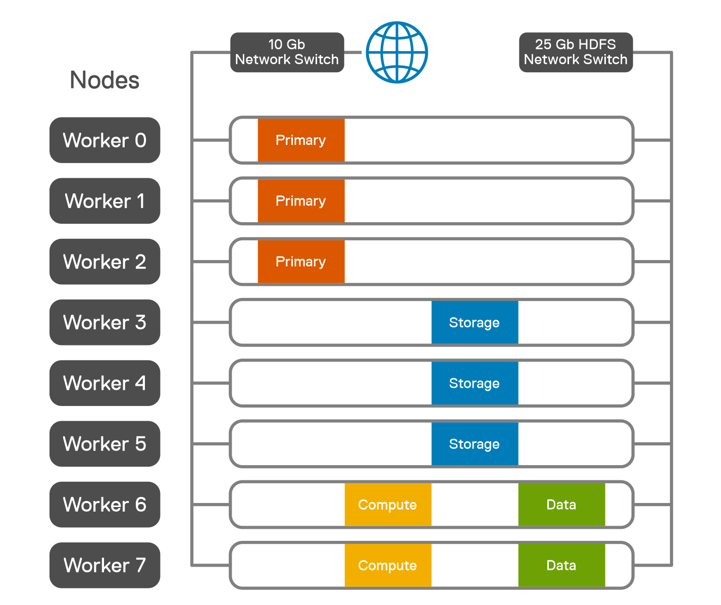 Pod placement across worker nodes
- To achieve the performance tuning of Microsoft SQL Server BDC cluster, see Microsoft performance guidelines.
- Tune the Microsoft SQL Server master instance based on the recommended guidelines.
- A testing tool like HammerDB documentation is run to validate the Microsoft SQL Server BDC for TPROC-H queries. HammerDB queries are run against the SQL Master instance.
- Follow the HammerDB best practices for SQL server guidelines to get the optimum performance. Although the results met the performance capabilities of the test system, the purpose of the testing was to validate Microsoft SQL Server BDC cluster and ensure that all best practices are implemented.
Conclusion
The validation was performed with a minimum lab hardware. For 1.2 TB of data loaded into Microsoft SQL Server, the QpH@Size was achieved at 220,800 for five virtual users as shown in the figure below. The overall test was completed for all the users in less than 30 minutes. It was observed that the PowerFlex system was not highly utilized while the test was carried out, including the PowerFlex storage, CPU, and memory, allowing the system to accommodate additional potential workload.
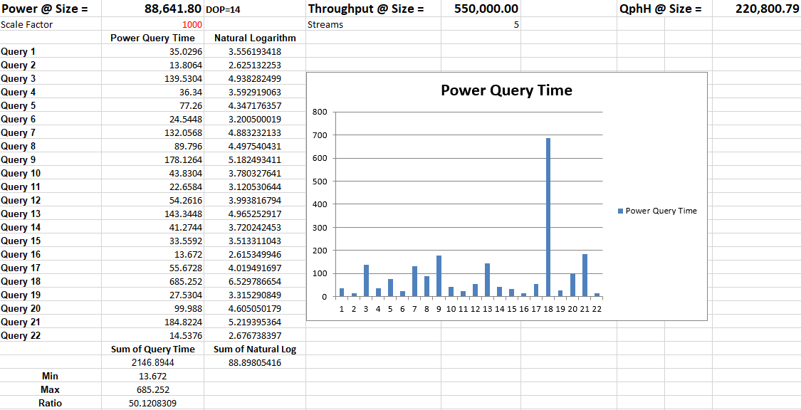 SQL Server BDC on PowerFlex validation
 The above test results show that SQL Server BDC deployed in a PowerFlex environment can provide a strong analytics platform for Data Warehousing type operations in addition to Big Data solutions.
To understand SQL Server BDC on upstream Kubernetes platform, see the paper SQL Server 2019 BDC on K8s.
References

PowerFlex Summer 2021 Updates Deliver on Execution, Compliance, and Confidence
Tue, 04 Jul 2023 09:48:51 -0000
|Read Time: 0 minutes
Execute Flawlessly – Comply Effortlessly – Be Confident
The summer 2021 release of Dell EMC PowerFlex Software-defined Infrastructure extends the PowerFlex family’s transformational superpowers, providing businesses with the agility to thrive in ever-changing economic and technological landscapes. The release of PowerFlex 3.6 and PowerFlex Manager 3.7 enables customers to supercharge their mission-critical workloads with enhanced automation and platform options. It safeguards workload execution with expanded continuity and compliance offerings. And businesses running PowerFlex can be confident in predictable outcomes at scale with new infrastructure insights, network resiliency enhancements, and integrated upgrade guidance.
Keep an eye on the important stuff
A highlight of this release is PowerFlex integration with Dell EMC CloudIQ, a cloud-based application that intelligently and proactively monitors the health of Dell EMC storage, data protection, HCI and other systems. Users can enjoy a single UI for multi-system, multi-site PowerFlex monitoring that includes system health, configuration/inventory, capacity usage, and performance. The PowerFlex system must be first connected to Dell EMC Secure Remote Services (SRS), and then CloudIQ is automatically enabled. Health scores are based on health check algorithms that use capacity, performance, configuration, components, and data protection criteria whose value is informed by PowerFlex alert data. Users can opt in to get health notifications via email or mobile phones, and the history of generated and cleared health issues is maintained for two years. After ingesting a couple of weeks of data, CloudIQ machine learning will begin looking for and noting IOPS and bandwidth anomalies. It also watches for and signals latency performance impacts.
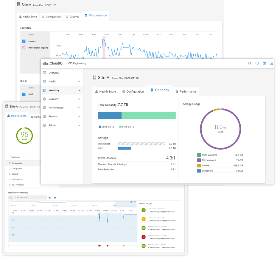
For information on adding your PowerFlex system(s) to CloudIQ see the Knowledge Base article. And to get a hands-on look at PowerFlex in CloudIQ, check out the online Simulator (log in with your support account) and see technical white papers and demo recordings on www.delltechnologies.com/cloudiq.
Be safe with your data out there
PowerFlex native asynchronous replication was introduced last year with version 3.5. Now, in PowerFlex 3.6, we have made it even more flexible and improved compliance targets. We cut the minimum RPO in half and now support RPOs as low as 15 seconds. We also added tooling to improve control over Replication Consistency Groups (RCGs) – sets of PowerFlex volumes being replicated together. RCGs can now be active or inactive, where inactive RCGs hold their configuration but use no additional system resources. The ability to terminate an RCG and leave it in an inactive state also improves the recovery process if a user runs out of journal capacity.
With this release, PowerFlex supports replication in VMware HCI environments. In this scenario, PowerFlex Manager 3.7 (and above) orchestrates resizing the Storage Virtual Machines (SVMs) and the addition of the Storage Data Replicators (SDRs) into the system. Because the orchestration is done by PowerFlex Manager, the option to replicate between PowerFlex HCI deployments running VMware is limited to appliance and rack deployments.
Systems running 3.5.x can be active replication peers with systems running 3.6, and the source and destination systems can be on different code versions long term. For further information about PowerFlex replication architecture, limitations and design considerations, see the Dell EMC PowerFlex: Introduction to Replication white paper.
Along with these internal replication improvements, we are introducing integration with VMware Site Recovery Manager (SRM) – disaster recovery management and automation software for virtual machines and their workloads. The PowerFlex Storage Replication Adapter (SRA) enables PowerFlex as the native replication engine for protecting VMs on vSphere datastores. The PowerFlex SRA is compatible with SRM 8.2 or 8.3, the Photon OS-based SRM appliances. And while we are introducing this with the current releases, the SRA is compatible with PowerFlex systems running 3.5.1.x and above. Users can create recovery plans to failover VMs to another site, fail back to the original, or use PowerFlex’s non-disruptive replication failover testing to run failover tests in SRM.
The SRA and installation instructions are available for download from the VMware website. For detailed information about the SRA implementation and usage examples, see the whitepaper on Disaster Recovery for Virtualized Workloads Dell EMC PowerFlex using VMware Site Recovery Manager.
The following figure shows an architecture overview of PowerFlex SRA and VMware SRM:
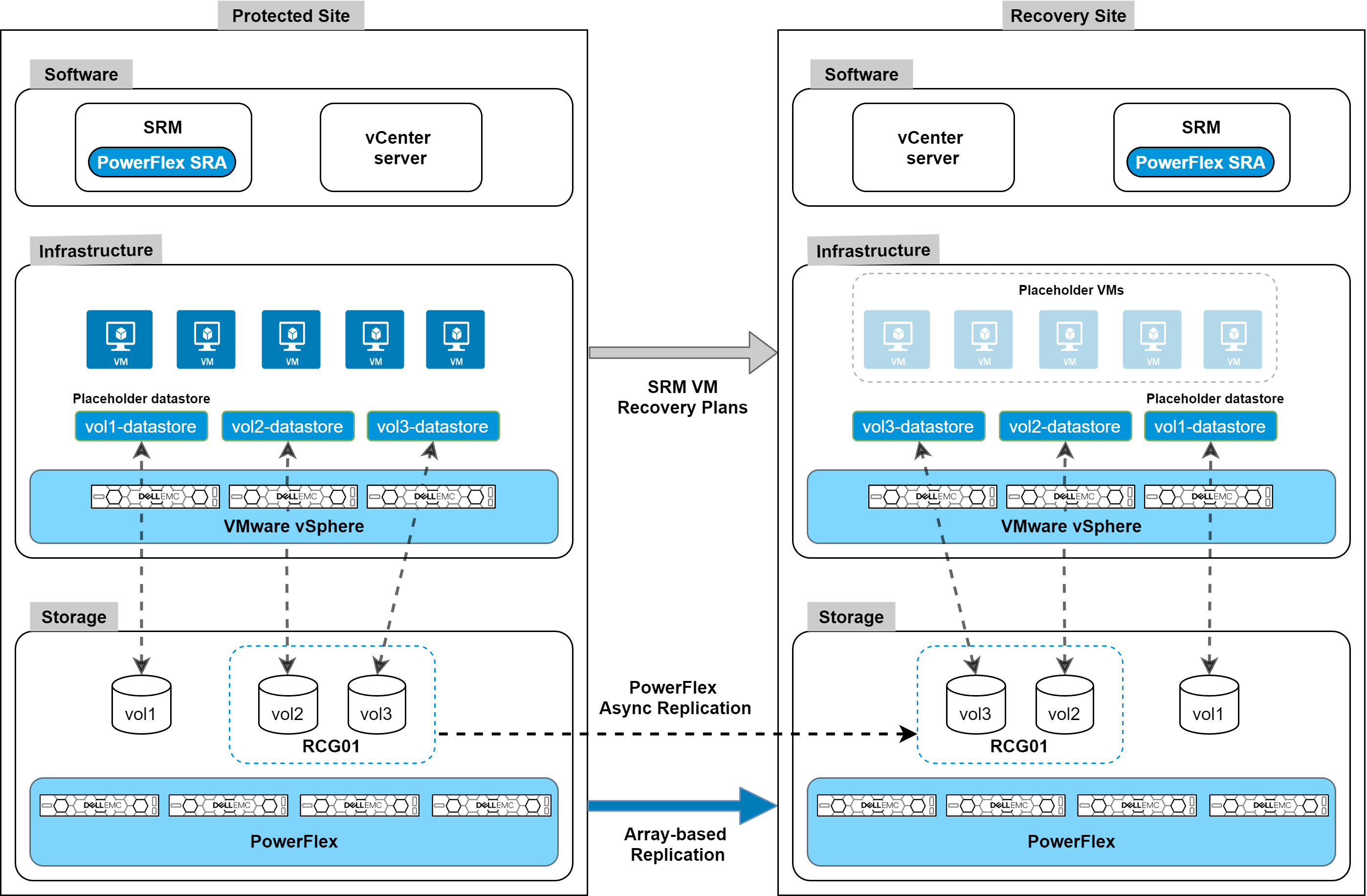
PowerFlex native replication, and the integration with VMware Site Recovery Manager, provide robust, crash-consistent data protection for disaster recovery and business continuity. But we are also introducing integration with Dell EMC AppSync for application-consistent copy lifecycle management. For customers using the wide range of supported databases and filesystems, AppSync v4.3 adds support for PowerFlex, seamlessly bringing PowerFlex’s superpowers into AppSync’s simplified copy data management. AppSync has deep integrations with Oracle, Microsoft SQL Server, Microsoft Exchange, and SAP HANA, and it enables VM-consistent copies of data stores and individual VM recovery for VMware environments. But it can also support other enterprise applications – like EPIC Cache, DB2, MySQL, etc. – through file system copies.
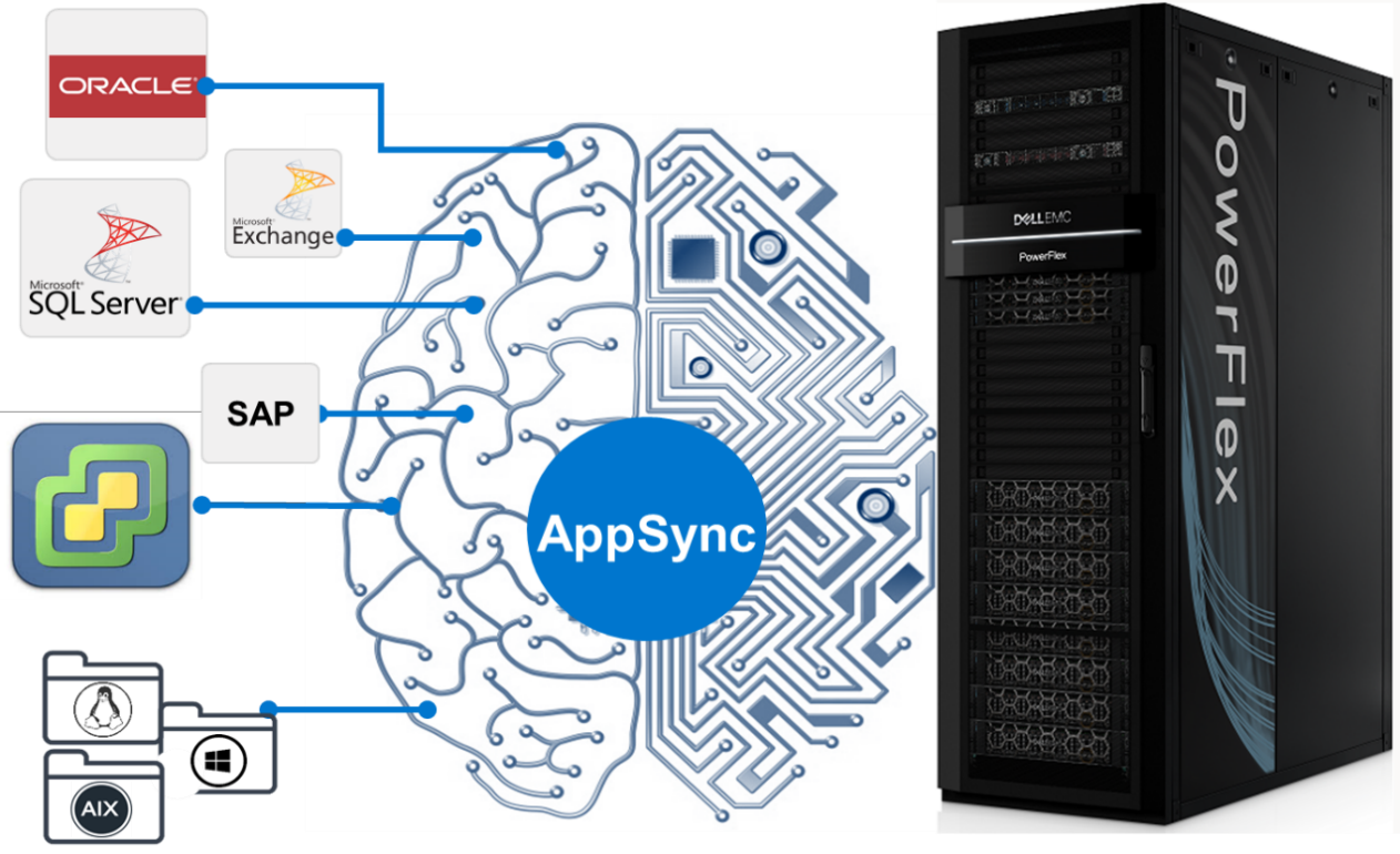
AppSync with PowerFlex integration will be available mid-July 2021. For information and examples, see the Dell EMC PowerFlex and AppSync integration video.
One more note on security. PowerFlex rack and appliance are now FIPS 140-2 compliant for data at rest and key management. Hardware based data at rest encryption is achieved using supported self-encrypting drives (SEDs), with the encryption engine running on the SEDs to deliver better performance and security. The SEDs based encryption claim is based on FIPS 140-2 Level 2 certification. Dell EMC CloudLink, the KMIP and FIPS 140-2 Level 1 (CloudLink Agent and CloudLink Server) compliant key manager, is used to manage SEDs encryption keys.
Automate (and containerize) all the things
PowerFlex software-defined infrastructure is eminently suited to cloud-native use cases and automatable workflows. There has been a lot of recent progress in PowerFlex’s support for these ecosystems. The Container Storage Interface (CSI) driver for PowerFlex continues to evolve, with support for accessing multiple PowerFlex clusters, ephemeral inline volumes, and importantly a containerized PowerFlex Storage Data Client (SDC) deployment and management. The containerized SDC allows CSI to inject the PowerFlex volume driver into the kernel of container-optimized operating systems that lack package managers. This provides PowerFlex CSI support for Red Hat CoreOS and Fedora Core OS. And it also enables integration of PowerFlex with RedHat OpenShift 4.6 and greater. The forthcoming CSI version 1.5 adds support for volume consistency groups and custom file system format options. Users can set specific disk format command parameters when provisioning a volume. Star and watch the GitHub Repository for the PowerFlex CSI Driver for updates.
In addition to this, Dell Technologies has been developing a set of Container Storage Modules (CSM) that complement the CSI drivers. PowerFlex is at the forefront of that effort, and there are several modules available for tech preview, with general availability coming later this year.
- Observability CSM: Provides exportable telemetry metrics for I/O performance & storage usage, for consumption in tools like Grafana and Prometheus. Bridges the observability gap between Kubernetes and PowerFlex storage admins.
- Authorization CSM: Provides a set of RBAC tools for PowerFlex and Kubernetes. This is an out-of-band tool proxying admin credentials and enabling the management of storage consumers and their limits (e.g., tenant segmentation, storage quota limits, isolation, auditing, etc.).
- Resiliency CSM: Provides stateful application fault protection & detection, resiliency for node failure and network disruptions. Reschedules failed pods on new resources and asks the CSI driver to un-map and re-map the persistent storage volumes to the online nodes.
Users can automate volume and snapshot lifecycle management with the PowerFlex Ansible Modules. They can also use the modules to gather facts about their PowerFlex systems and manage various storage pool and SDC details. The Ansible modules are available on GitHub and Ansible Galaxy. They work with Ansible 2.9 or later and require the PowerFlex Python SDK (which may also be used by itself to facilitate authentication to and interaction with a PowerFlex cluster). Again, watch the repositories for additional modules and expansions in the near future.
All these automation tools leverage and rely upon the PowerFlex REST API. And Dell Technologies has introduced a new Developer Portal, where the APIs for many products can be explored. The PowerFlex API, along with explanations and usage examples, can be found at https://developer.dell.com/apis/4008/versions/3.6/docs.
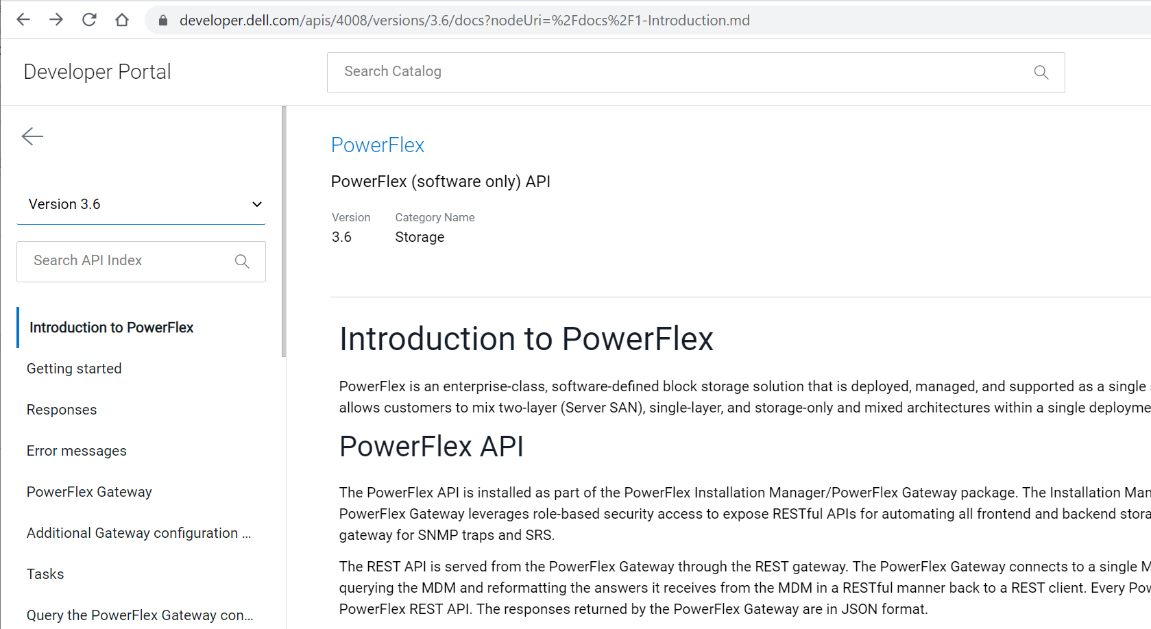
Always keep on improving
With every release, PowerFlex and PowerFlex Manager get faster, more secure, and more easily manageable. In PowerFlex 3.6 there are a number of UI enhancements, including simplification of menus, better capacity reporting around data reduction, a new dedicated area for snapshots and snapshot policy management, and – following on Dell Technologies’ drive towards more inclusive language – a change in the labels for the MDM cluster roles. “Master” and “Slave” roles are now “Primary” and “Secondary”.
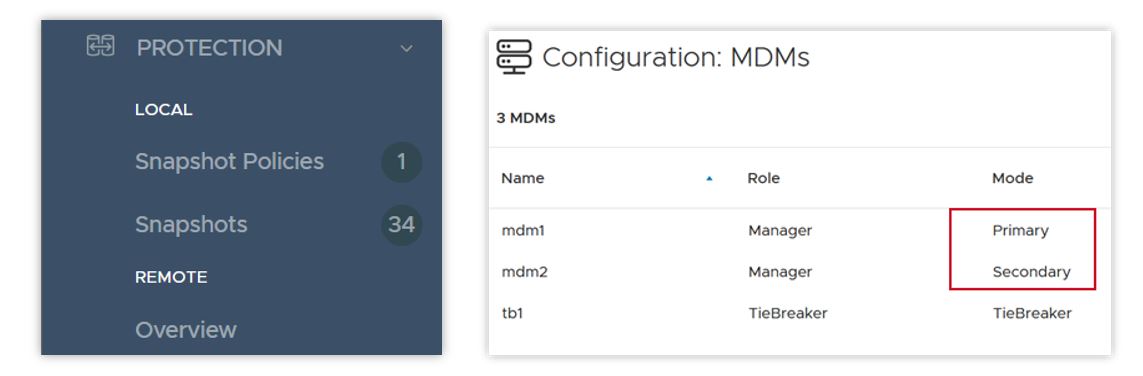
PowerFlex 3.6 introduces support for Oracle Linux Virtualization (KVM based), which adds a supported hypervisor layer to the previous support for Oracle Enterprise Linux. This advances the numerous Oracle database deployments on PowerFlex, providing improved Oracle supportability while still offering the great cost-effectiveness PowerFlex offers for running Oracle. For detailed information on installing and configuring, please refer to the Oracle Linux KVM on PowerFlex white paper.
In the software-defined storage layer itself, version 3.6 doubles the number of Storage Data Clients (the consumers of PowerFlex volumes) per system to 2048. This doubles the number of hosts that can map volumes from PowerFlex storage pools. The software is also smarter when it comes to detecting and handling network error cases. In some disaggregated, or two-layer, systems where the SDCs live on a separate network than the storage cluster itself, a network path impairment between an SDC and a single Storage Data Server (SDS) node can cause I/O failures – even when there isn’t a general network failure in the cluster. In version 3.6 if such a disruption occurs, the SDC can use another SDS in the system to proxy the I/O to its original destination. Users are alerted until the problem is cleared, but I/O continues uninterrupted.
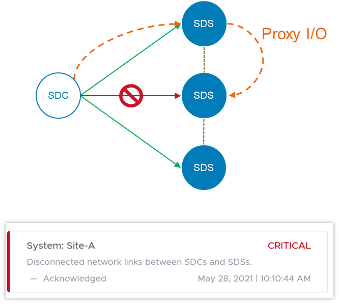
Because of the highly distributed architecture of PowerFlex, ports or sockets experiencing frequent disconnects (flapping), can cause overall system performance issues. 3.6 detects this and proactively disqualifies the path, preventing general disruption across the system.
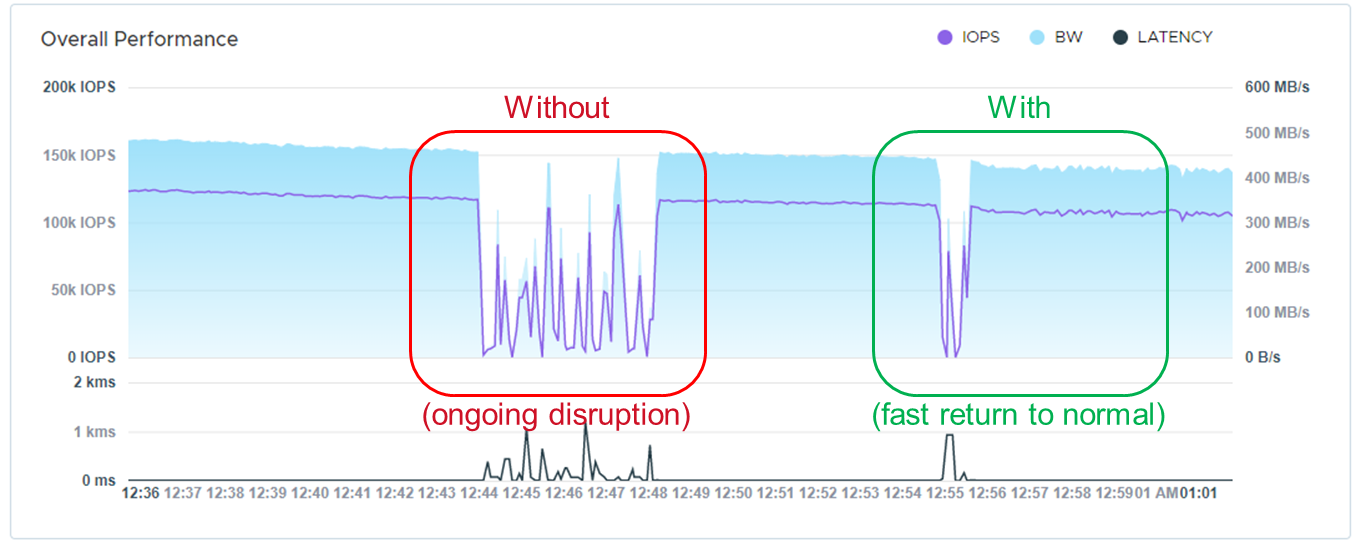
In version 3.5, we introduced Protected Maintenance Mode (PMM), a super-safe way to put a node into maintenance while nevertheless avoiding a lengthy data-rehydration process at the end. Now, PMM makes use of the highly parallel many-to-many rebalancing algorithm, as a node goes into maintenance. Depending on the amount of data stored on the node, this can still be a long process, and other things can change in the system as it’s happening. PowerFlex 3.6 adds an auto-abort feature, in which the system continually scans for hardware or capacity issues that would prevent the node from completely entering PMM. If any flags are raised, the system will abort the process and notify the user. More information on maintenance modes, and the new PMM auto-abort feature, can be found in this whitepaper.
PowerFlex Manager 3.7 has gotten much more powerful as well. Foremost among the improvements is a new Compatibility Management feature. This new feature helps customers automatically identify the recommended upgrade paths for both the PowerFlex Manager appliance itself and the system RCM/IC upgrade. Prior to this release, whenever a customer or Dell Professional Services wished to do an upgrade, it took a lot of effort and time to manually investigate the documentation and compatibility matrixes to understand all of the upgrade rules – what are the allowed upgrade paths, which PowerFlex Manager version works with which RCM/IC versions, etc.
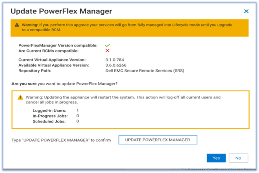
The new Compatibility Management tools eliminate the work and assist users by automatically identifying recommended upgrade paths. To determine which paths are valid and which are not, PowerFlex Manager uses information that is provided in a compatibility matrix file. The compatibility matrix file maps all the known valid and invalid paths for all previous releases of the software. It breaks the possible upgrade paths down as:
- Recommended: tested or implied as tested
- Supported: allowed, but not necessarily tested
- Not Allowed: unsupported update path
PowerFlex Manager 3.7 also introduces support for vSphere 7.0 U2. Upgrading to this version requires a manual vCenter upgrade. But then PowerFlex Manager will take over and manage the ESXi clusters. PowerFlex Manager 3.7 supports VMware ESXi 7.0 Update 2 installation, upgrade, and expansion operations for both hyperconverged and compute-only services. Users can deploy new services, add existing services running VMware ESXi 7.0 U2, or expand existing services. PowerFlex Manager also supports upgrades of VMware ESXi clusters in hyperconverged or compute-only services. You can upgrade VMware ESXi clusters from version 6.5, 6.7, or 7.0 to VMware ESXi 7.0 Update 2.
When you deploy a new ESXi 7.0U2 service, PowerFlex Manager automatically deploys two service volumes and maps these volumes to two heartbeat datastores on shared storage. PowerFlex Manager also deploys three vSphere Cluster Services (vCLS) VMs for the cluster.
PowerFlex Manager introduces several other enhancements in this release. It now supports 32k volumes per Service, aligned with PowerFlex core software volume scalability. It has enhanced security for SMB/NFS. A user-specific account is now required to gain access to the SMB share. PowerFlex Manager also updates the NFS share configuration when a user upgrades or restores the virtual appliance. PowerFlex Manager has disabled support for the SMBv1 protocol. PowerFlex Manager now uses SMBv2 or SMBv3 to enhance security.
It has also expanded its management capabilities over the PowerFlex Presentation Server and Gateway services. Prior to this release, PowerFlex Manager could deploy a Presentation Server (which hosts the WebUI) but not upgrade it. Now, PowerFlex Manager 3.7 can both discover existing instances and upgrade Presentation Servers. Similarly, it has gained the ability to upgrade the OS for the Gateway (which hosts the REST API). Prior to this release, PowerFlex Manager could only upgrade the Gateway RPM package without upgrading and patching the OS of the Gateway. Now PowerFlex Manager 3.7 can do both.
But it’s not all about software
This release adds support for a broader array of NVIDIA GPUs. Next-gen NVIDIA acceleration cards are now available for customers looking to run specialized, high-performance computing and analytics applications - Quadro RTX 6000, Quadro RTX 8000, A40, and A100. And we also introduce a small form factor GPU that can be used in the 1U R640-based PowerFlex Nodes – the NVIDIA A100. The past year demonstrated the importance supporting remote workers with virtual desktops, and PowerFlex supports GPU implementations on Citrix and VMware VDI.
We now support the Dell PowerSwitch S5296F-ON for the PowerFlex appliance. The S5295 has 96x 10/25G SFP28 ports and 8x 100G QSFP28 ports. It can support high node counts in a single cabinet, if the high oversubscription ratio is acceptable. We also introduce support for the Cisco Nexus 93180YC-FX, for use as either an access or an aggregation switch, and the Cisco 9364C-GX, for use as either a leaf or a spine switch, with 64x 100G ports.
Virtualized network infrastructure continues to grow in capability and deployment share. NSX-T™ is VMware's software-defined-network infrastructure that addresses cross-cloud needs for VM-centric network services and security. The PowerFlex appliance now joins the PowerFlex rack, in supporting NSX-T Ready configurations. “NSX-T Ready” means that the hardware configuration meets NSX-T requirements. The customer will provide NSX-T software and deploy with assistance from VMware or Dell Professional Services. The enabling components are:
- A 4-node PowerFlex management cluster, available to host the NSX-T controller VMs
- Appliance-specific NSX-T edge nodes (need 2 to 8 for running the NSX-T edge services)
- High-level NSX-T topologies and considerations available in the PowerFlex Appliance Network Planning Guide
- PowerFlex Manager will run the NSX-T edge nodes in Lifecyle Mode
As with the PowerFlex rack, appliance NSX-T edge nodes are “service appliances” that are dedicated to run network services, while the newly available HA appliance management nodes run the NSX-T management VMs. PowerFlex Manager can assist in deploying the edge nodes and will lifecycle the hardware aspects.
Wrap it up
Thanks for taking time to read about what’s new with Dell EMC PowerFlex software-defined infrastructure. We haven’t even been able to cover all the great new things being introduced this summer. Supercharge your mission-critical workloads flawlessly with enhanced automation, effortlessly enable business continuity and compliance, and confidently manage your data center operations at scale. To continue exploring, visit us on the Dell Technologies website for PowerFlex.

Copy data management with AppSync for applications running on Dell EMC PowerFlex
Wed, 23 Jun 2021 15:04:50 -0000
|Read Time: 0 minutes
Dell EMC PowerFlex, a premier software-defined platform for your mission-critical workloads, empowers organizations to move faster and respond effectively to rapidly changing business needs. PowerFlex provides unprecedented freedom to deploy and scale critical workloads that drive your business, while ensuring exceptional performance, simplicity, and manageability.
As the world of DevOps evolves, agility in IT operations is critical in order to rapidly provision environments for test and development. This agility requires a platform which includes integrated copy data management for DevOps environments.
The PowerFlex software-defined storage solution enables this transformational agility for organizations looking to modernize their DevOps application development operation and empowers organizations to move faster and respond more effectively to rapidly changing business needs.
Dell EMC AppSync for PowerFlex provides a single user interface that simplifies, orchestrates and automates the process of generating and consuming DevOps data across all enterprise database applications deployed on PowerFlex.
AppSync for PowerFlex provides simple automated copy creation and consumption, eliminating manual steps or custom scripts. AppSync integrates tightly with host environments and database applications including, but not limited to, Oracle and SQL Server. With AppSync, applications owners, database administrators, and storage administrators get on - and stay on - the same page through a transparent copy workflow.
Dell EMC AppSync for PowerFlex allows you to protect, restore and repurpose application data, satisfying any DevOps requirements.
AppSync version 4.3 enables support for the PowerFlex family - rack, appliance and ready node consumption options.
AppSync architecture
The architecture of AppSync has three major components:
- AppSync server is deployed on a Windows server system, either physical or virtual. It controls all workflow activities, manages the alerting and monitoring aspects, and persists internal data in a PostgreSQL database.
- AppSync host plug-ins are installed on all source and mount hosts. They provide integration with the operating systems and the applications that are hosted on the hosts. These applications include Microsoft Exchange, Microsoft SQL Server®, Oracle®, SAP HANA, and VMware datastores or other file systems. With VMware datastore replication, there is no host plug-in because AppSync communicates directly with the VMware vCenter® server.
- AppSync user interface is the web-based UI for the AppSync copy-management feature. AppSync can also be managed using the vSphere VSI plug-in, REST API, or command-line interface (CLI).
Registering the PowerFlex system with AppSync
AppSync interacts with the PowerFlex system by communicating with PowerFlex Gateway using API calls:
1. On the AppSync console, select Settings > Infrastructure Resources > STORAGE SYSTEMS. Click ADD SYSTEMS.
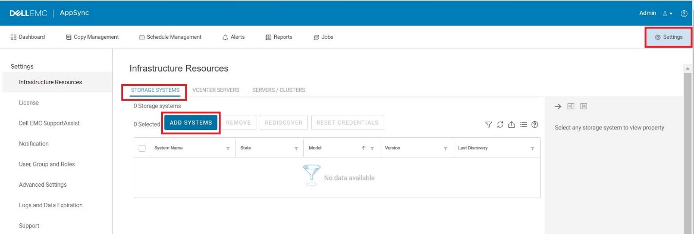
2. Under Select System Type, choose PowerFlex.
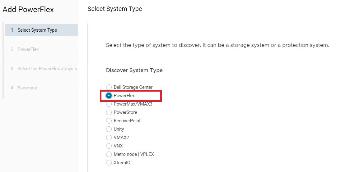
3. Enter the PowerFlex Gateway IP and credentials to configure the storage system.
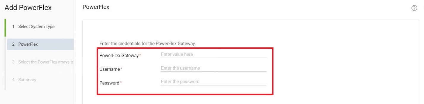
4. Review the configurations in the Summary page and click FINISH to register the PowerFlex system.
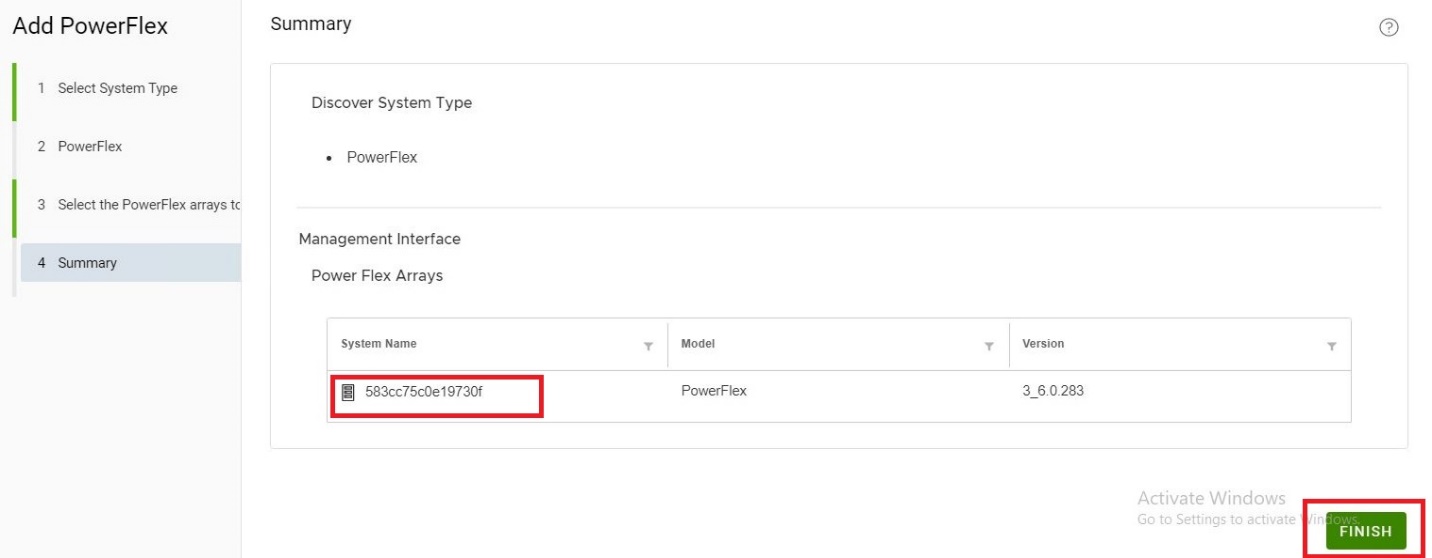
AppSync service plans
AppSync provides intuitive workflows to set up protection and repurposing jobs (called Service Plans) that provide end-to-end automation of all the steps from application discovery and storage mapping to mounting copies to the target hosts. Service plans can be scheduled with alert emails to easily track their status. AppSync also provides an application protection monitoring and reporting service that generates alerts if SLAs are not met or if a service plan fails.
AppSync supports three types of service plans:
- Bronze — You can use the Bronze service plan to create local copies of your applications data
- Silver — You can use the Silver service plan to create remote copies of your applications data
- Gold — You can use the Gold service plan to create both local and remote copies of your applications data
AppSync features
- AppSync Protect
AppSync enables application owners and DBAs to protect, restore. and repurpose their data to satisfy their unique copy requirements. This accelerates and improves processes like test and dev by providing the latest production data for high quality product releases. AppSync’s support for second generation copies (a copy of a copy) allows for required data masking, filtering and obfuscation by DBAs so that end-users of data have access to only the data that they need. At any given point of time, storage admins can get a complete picture of the copy landscape so that they are aware of capacity utilization and the scope for optimization.
- AppSync repurposing
AppSync allows you to create copies of your database and file systems for application testing and validation, test and development, reporting, data masking, and data analytics. AppSync identifies copies that are created from a repurpose action as first-generation and second-generation copies. The source of a second-generation copy is a first-generation copy. You can create multiple second-generation copies from a first-generation copy.
AppSync support for PowerFlex
- PowerFlex 3.0.1 and above
- Bronze & Silver service plan
AppSync integration with PowerFlex videos
- Dell EMC PowerFlex and AppSync integration
- Integrated copy data management with AppSync for SQL Server running on Dell EMC PowerFlex
- Integrated copy data management with AppSync for Oracle running on Dell EMC PowerFlex
- Integrated copy data management with AppSync for File Systems running on Dell EMC PowerFlex
Conclusion
AppSync integration enables PowerFlex users to protect, restore and repurpose their data to satisfy their unique copy requirements for their enterprise applications users.
References
- Dell EMC Support Page
https://www.dell.com/support/home/us/en/19?app=products&~ck=mn
- Dell EMC AppSync Copy Data Management Software
https://www.delltechnologies.com/en-us/storage/appsync-copy-data-management-software.htm
- AppSync Licensing Guide
CloudLink 7.1: Simplifying datacenter security
Fri, 23 Apr 2021 12:10:59 -0000
|Read Time: 0 minutes
Are you feeling safe about the security of your data center’s infrastructure? Chances are, you aren’t. According to a recent poll1, 74% of customers report experiencing some form of cyber attack in the last twelve months, and 86% were concerned about potential cyberattacks. Clearly, data center security is a topic than can no longer be ignored - and most of our customers are taking steps to ensure their data is safe. Yet even though it’s necessary, adopting data center security can be confusing, complex, and difficult to implement.
Dell EMC CloudLink aides our customers in this effort by being reliable, flexible, and easy to use. Our 7.1 release adds new tools to our toolbox including shallow rekey for our Container based encryption, support for vVols encryption and IPv6 only environments, and the new Secure Configuration Summary page designed to make security audits of CloudLink a breeze.
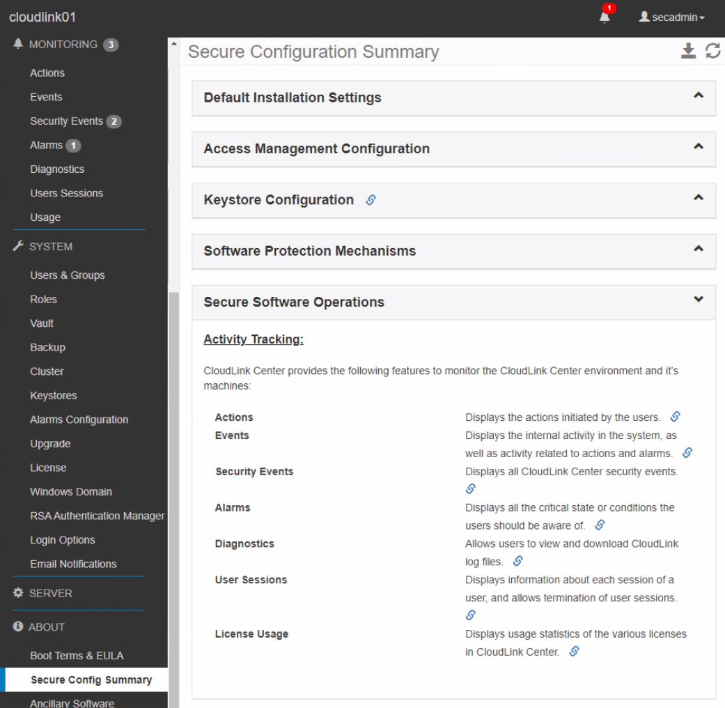
Every security related framework published discusses the need for regular monitoring and assessment of implemented security controls to ensure that the products and deployment are meeting relevant industry standards. Such activities usually include the dreaded yearly security audit. Datacenter administrators view this effort with disfavor because it takes time out of their already busy schedule to walk through the deployment with the auditor to prove compliance.
In the past we’ve heard from our customers that the CloudLink GUI is easy enough to navigate that security audit reviews weren’t too painful, but they occasionally expressed that it would be nice to make them a little bit easier. Well we heard their requests loud and clear and have obliged with the Secure Configuration Summary. We’ve gathered the information commonly requested during security audits onto one page so when the security administrator and auditor go to CloudLink for a review, it’s a one stop shop.
With audits though, simply viewing configuration settings isn’t enough as most auditors require tangible proof to attach to their reports. Screen shots work but we offer something better – the ability to export the configuration settings provided on the summary page. As with most of our GUI pages, you can export the Secure Configuration Summary to a handy-dandy spreadsheet which can be presented directly to the auditor. A one click audit review – can it get any easier than that?
Of course, not all audits are the same and some requirements are more extensive than others. To accommodate this eventuality, our summary page provides direct links to the configuration pages for each setting. If an auditor needs more information on a particular configuration, simply jump to the relevant page, review, and download an export if needed.
Encryption is hard and it can be a challenge to understand, implement, and maintain. We understand that most of our customers are not in the datacenter security business. CloudLink strives to make data encryption in the datacenter a simple, set it and forget it task, so that our customers can focus on their core business, not on trying to figure out how to keep their data safe – that’s our job.
If you would like to know more about CloudLink and our latest release please visit our website and reach out to your Dell Technologies sales team to ask how we can make data encryption easy for you too.
1 Source: statista.com

Deploying Tanzu Application Services on Dell EMC PowerFlex
Tue, 15 Dec 2020 14:35:58 -0000
|Read Time: 0 minutes
Introduction
Tanzu Application Service (TAS) architecture provides the best approach available today to enable agility at scale with the reliability that is must to address these challenges. PowerFlex family offers key value propositions of traditional and cloud-native production workloads, deployment flexibility, linear scalability, predictable high performance, and enterprise-grade resilience.
Tanzu Application Service (TAS)
The VMware Tanzu Application Service (TAS) is based on Cloud Foundry –an open-source cloud application platform that provides a choice of clouds, developer frameworks, and application services. Cloud Foundry is a multi-cloud platform for the deployment, management, and continuous delivery of applications, containers, and functions. TAS abstracts away the process of setting up and managing an application runtime environment so that developers can focus solely on their applications and associated data. Running a single command—cf push—creates a scalable environment for your application in seconds, which might otherwise take hours to spin up manually. TAS allows developers to deploy and deliver software quickly, without the need of managing the underlying infrastructure.
PowerFlex
PowerFlex (previously VxFlex OS) is the software foundation of PowerFlex software-defined storage. It is a unified compute, storage and networking solution delivering scale-out block storage service designed to deliver flexibility, elasticity, and simplicity with predictable high performance and resiliency at scale.
The PowerFlex platform is available in multiple consumption options to help customers meet their project and data center requirements. PowerFlex appliance and PowerFlex rack provide customers comprehensive IT Operations Management (ITOM) and life cycle management (LCM) of the entire infrastructure stack in addition to sophisticated high-performance, scalable, resilient storage services. PowerFlex appliance and PowerFlex rack are the two preferred and proactively marketed consumption options. PowerFlex is also available on VxFlex Ready Nodes for those customers interested in software-defined compliant hardware without the ITOM and LCM capabilities.
PowerFlex software-define storage with unified compute and networking offers flexibility of deployment architecture to help best meet the specific deployment and architectural requirements. PowerFlex can be deployed in a two-layer for asymmetrical scaling of compute and storage for “right-sizing capacities, single-layer (HCI), or in mixed architecture.
Deploying TAS on PowerFlex
For this example, a PowerFlex production cluster is set up using a Hyperconverged configuration. The production cluster has connectivity to the customer-data network and the private backend PowerFlex storage network. The PowerFlex production cluster consists of a minimum of four servers that host the workload and PowerFlex storage VMs. All the nodes are part of a single ESXi Cluster and part of the same PowerFlex Cluster. Each node contributes all their internal disk resources to PowerFlex cluster.
The PowerFlex management software manages the capacity of all of the disks and acts as a back-end for data access by presenting storage volumes to be consumed by the applications running on the nodes. PowerFlex Manager also provides the essential operational controls and lifecycle management tools. The production cluster hosts the compute nodes that are used for deployment of TAS VMs. TAS components are deployed across three dedicated compute clusters that are designated as three availability zones. These compute clusters are managed by the same 'compute workload' vCenter as the dedicated Edge cluster. The following figure depicts the layout in the lab environment:
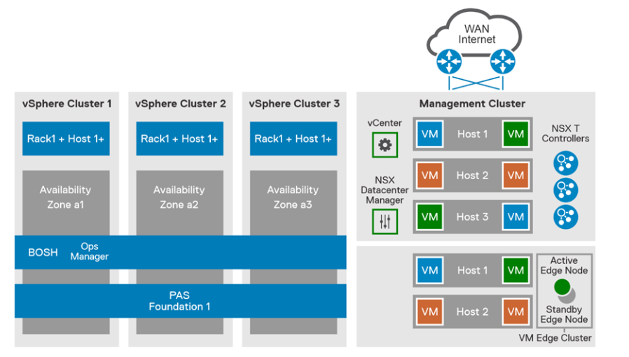
Figure 1. PowerFlex production cluster
The compute infrastructure illustrates the best practice architecture using 3 AZ’s using PowerFlex rack in hyperconverged configured nodes. This design ensures the high availability of nodes (i.e., nodes in AZ1 will still function if AZ2 or AZ3 goes down). A dedicated compute cluster in each AZ’s combines to form Isolation Zone (IZ). These AZ’s can be used to deploy and run the TAS stateful workloads requiring persistent storage. On the PowerFlex storage we have created volumes in the backend which are being mapped to vSphere as Datastores.
PowerFlex storage distributed data layout scheme is designed to maximize protection and optimize performance. A single volume is divided into chunks. These chunks will be distributed (striped) on physical disks throughout the cluster, in a balanced and random manner. Each chunk has a total of two copies for redundancy.
PowerFlex can be feature configured optionally to achieve additional data redundancy by enabling the feature Fault sets. Persistent Storage for each AZ could be its own PowerFlex cluster. By implementing PowerFlex feature Fault sets we can ensure that the persistent data availability all time. Fault Sets are subgroup of SDS s (Software defined Storage) installed on host servers within a Protection Domain. PowerFlex OS will mirror data for a Fault Set on SDSs that are outside the Fault Set. Thus, availability is assured even if all the servers within one Fault Set fail simultaneously.
PowerFlex enables flexible scale out capabilities for your data center also provides unparalleled elasticity and scalability. Start with a small environment for your proof of concept or a new application and add nodes as needed when requirements evolve.
The solution mentioned in this blog provides recommendations for deploying a highly available and production-ready Tanzu Application Service on Dell EMC PowerFlex rack infrastructure platform to meet the performance, scalability, resiliency, and availability requirements and describes its hardware and software components. For complete information, see Tanzu Application Services on PowerFlex rack - Solution Guide.
References

Introducing the PowerFlex Management Pack for vRealize Operations
Mon, 02 Nov 2020 13:09:42 -0000
|Read Time: 0 minutes
By Vineeth A C
Achieving operation efficiency in today’s modern cloud infrastructure brings automation to the forefront. Centralized visibility provides a key piece of the insight needed to understand if there are operational inefficiencies for taking actions that mitigate business disruption.
We are pleased to share the general availability of Dell EMC PowerFlex Management Pack for vRealize Operations 8.x. The PowerFlex MP for vROps extends the visibility of PowerFlex systems into vROps where IT can monitor their complete data center and cloud operations. It is available to all PowerFlex rack and appliance customers at no additional cost. This brings additional value to the comprehensive IT operations management functionality delivered by PowerFlex Manager that enables full life cycle management of the unified compute and software defined storage solution.
The management pack queries and collects key PowerFlex metrics for storage, compute, networking, and server hardware using APIs and ingests into vROps that can be visualized using the out-of-the-box dashboards. It also provides a detailed system level view that shows the health status and relationship between different components of the PowerFlex system.
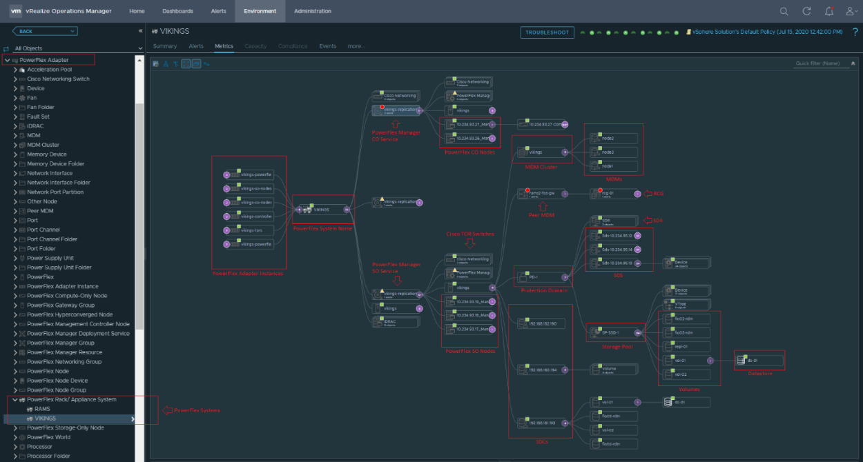
Key features and capabilities
Dashboards: The management pack includes 13 default dashboards showing details of PowerFlex storage, PowerFlex Manager, PowerFlex nodes, network switches, ESXi hosts, and clusters. These configurable dashboards provide user customizable data displays that adjust to meet a wide variety of requirements.
Predefined symptoms and alert definitions: The management pack includes 166 symptom definitions and 152 alert definitions based on engineering best practices for the PowerFlex systems. Symptoms and alerts can be customized by the user to meet the demand of their environment.
Historical data: This is available for all PowerFlex Adapter resource kinds. This data provides a view of consumption over time and includes capacity forecasting based on usage for PowerFlex storage.
Network topology and relationship: The topology tree functionality available in vROps is extremely useful when mapping relationships between nodes, network interfaces, switch port, VLAN, port-channel, and vPC.
Detailed metric collection: In addition to the default dashboards, users have the option of drilling into specific metrics for nearly all available data from the components of PowerFlex system, even if it is not included in a dashboard.
Multiple PowerFlex systems awareness: Ability to group and differentiate multiple PowerFlex systems.
PowerFlex node type differentiation: Ability to identify and classify compute, storage, hyperconverged, and management controller nodes.
Sample dashboards
PowerFlex Details: This dashboard shows all the PowerFlex storage KPIs with historical data providing a view of storage performance utilization over time.
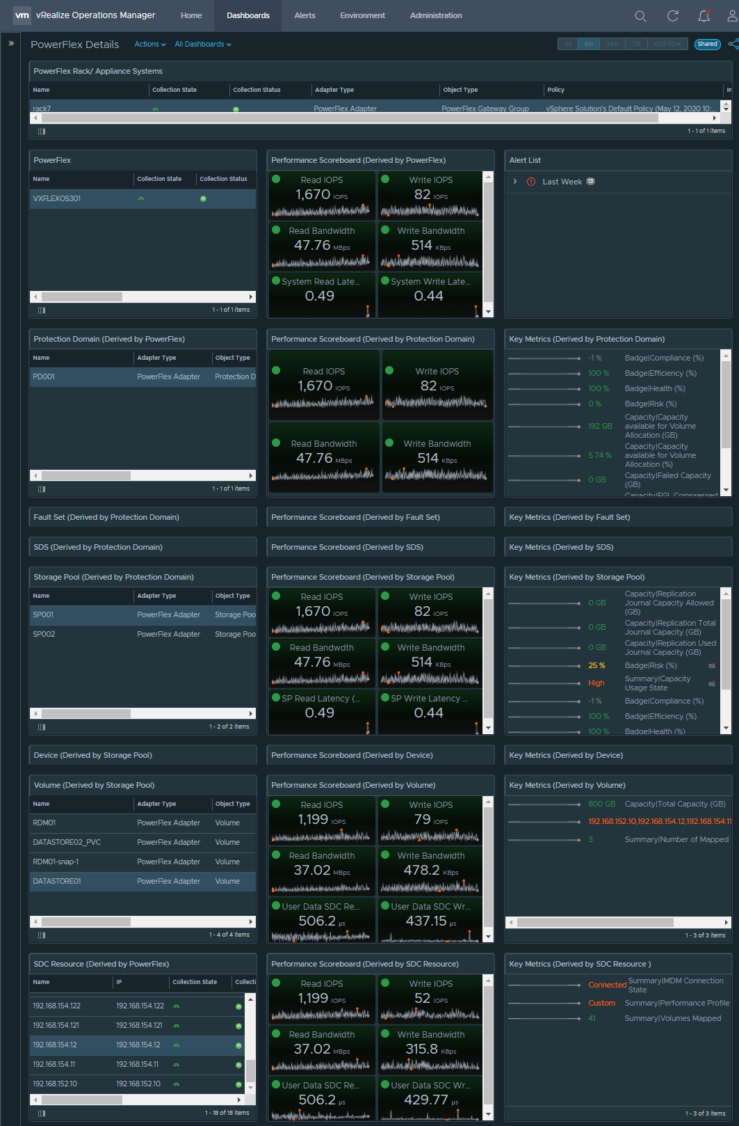
PowerFlex Node Summary: You can monitor the health status of all your PowerFlex nodes and its hardware components in this dashboard.
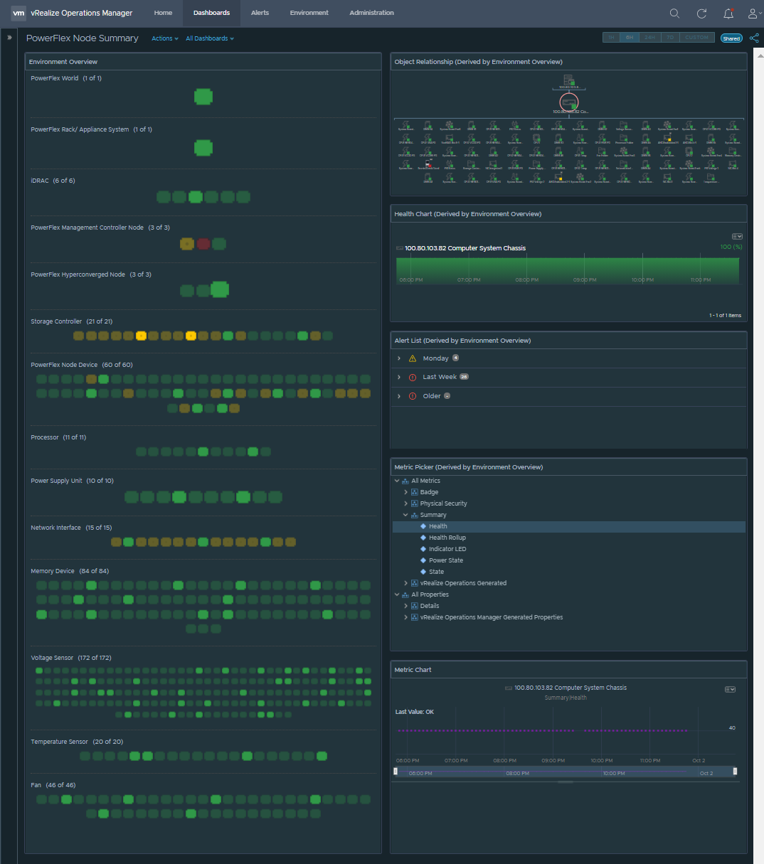
PowerFlex Networking Performance: This dashboard shows network KPIs like throughput, errors, packet discards with historical data providing a view of network utilization over time.
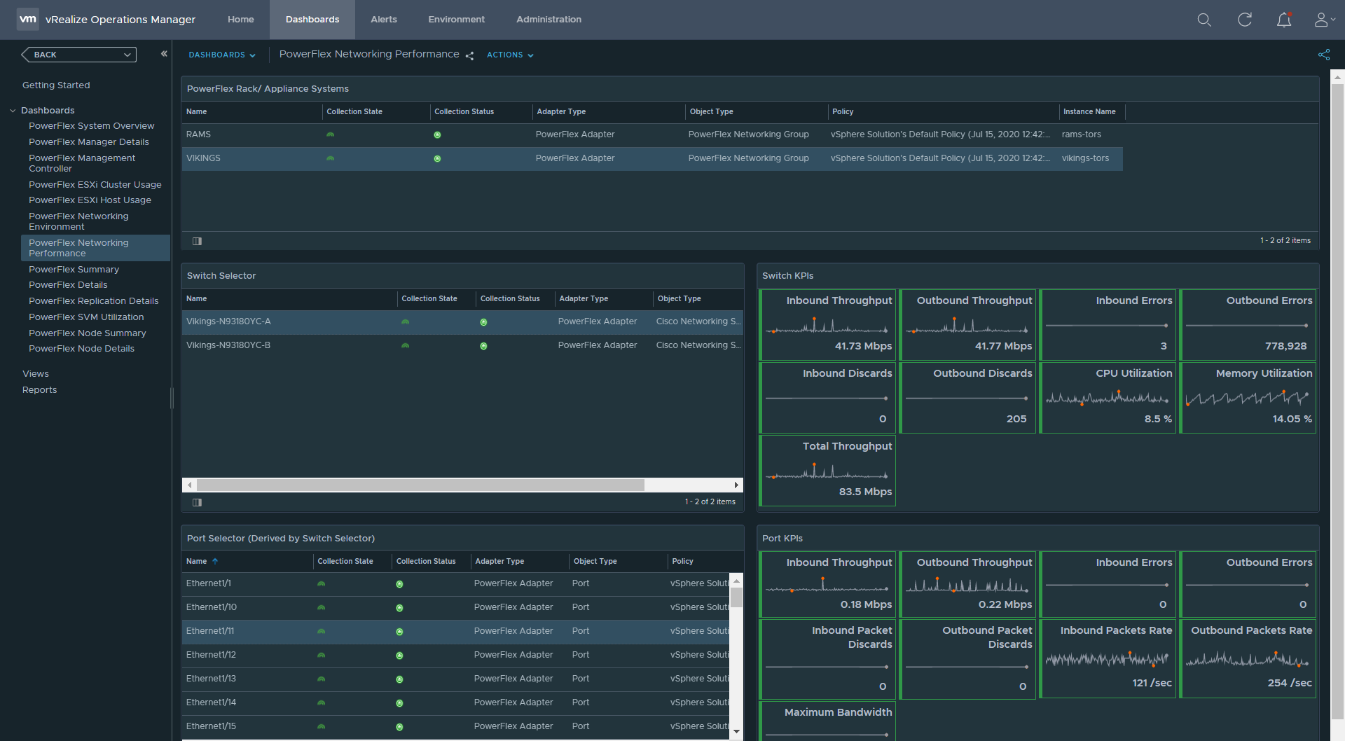
For customers who have already invested in vRealize Operations, this management pack is a great value add to monitor their PowerFlex systems. It is an end-to-end monitoring and alerting solution for PowerFlex infrastructure using vROps. It helps customers significantly in terms of capacity planning based on the historical data of resource consumption over time. It also helps to identify usage trends and provides insight to understand if there are operational issues/ inefficiencies for taking necessary actions to avoid service outages and mitigate business disruption. This integration with VMware vRealize Operations reduces operational complexity by using a unified platform to monitor and manage private data center infrastructure, as well as hybrid and multi-cloud environments.
References
- Download the PowerFlex Management Pack from the Flexera portal.
- Visit Infohub for product documentation.
- Visit PowerFlex site for complete information about PowerFlex software-defined storage.

Demystifying CSI plug-in for PowerFlex (persistent volumes) with Red Hat OpenShift
Tue, 20 Oct 2020 12:16:04 -0000
|Read Time: 0 minutes
Raghvendra Tripathi
SunilKumar HS
The Container Storage Interface (CSI) is a standard for exposing file and block storage to containerized workloads on Kubernetes, OpenShift and so on. CSI helps third-party storage providers (for example PowerFlex) to write plugins for OpenShift to consume storage from backends as persistent storage.
CSI architecture
CSI driver for Dell EMC VxFlex OS can be installed using Dell EMC Storage CSI Operator. It is a community operator and can be deployed using OperatorHub.io.
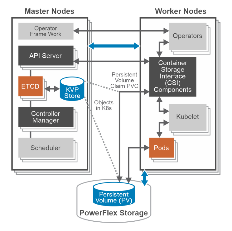
Master nodes components do not communicate directly with CSI driver. It interacts only with API server on Master nodes. It MUST watch the Kubernetes API and trigger the appropriate CSI operations against it. Kubelet discovers CSI drivers using kubelet plug-in registration mechanism. It directly issues calls to CSI driver.
CSI components
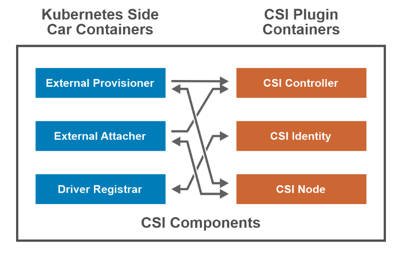
External Provisioner –The CSI external provisioner is a sidecar container that watches the k8s API server for PersistentVolumeClaim objects. It calls CreateVolume against the specified CSI endpoint to provision a volume.
External Attacher – The CSI external attacher is a sidecar container that watches the API server for VolumeAttachment objects and triggers controller [Publish|Unpublish] volume operations against a CSI endpoint.
Driver Registrar
- Node-driver-registrar – The CSI node driver registrar is a sidecar container that fetches driver information from a CSI endpoint and registers it with the kubelet on that node.
- Cluster-driver-registrar – The CSI cluster driver registrar is a sidecar container that registers a CSI driver with a k8s cluster by creating a CSIDriver object.
CSI Controller plug-in – The controller component can be deployed as a Deployment or StatefulSet on any node in the cluster. It consists of the CSI driver that implements the CSI Controller service.
CSI Identity – It enables k8s components and CSI containers to identify the driver.
CSI Node Plugin –The node component should be deployed on every node in the cluster through a DaemonSet. It consists of the CSI driver that implements the CSI Node service and the node driver registrar sidecar container.
CSI and Persistent Storage
Storage within OpenShift Container Platform 4.x is managed from worker nodes. The CSI API uses two new resources: PersistentVolume (PV) and PersistentVolumeClaim (PVC) objects.
Persistent Volumes – Kubernetes provides physical storage devices to the cluster in the form of objects called Persistent Volumes.
apiVersion: v1 kind: PersistentVolume spec: accessModes: - ReadWriteOnce capacity: storage: 104Gi claimRef: apiVersion: v1 kind: PersistentVolumeClaim name: test-vol namespace: powerflex . . csi: driver: csi-vxflexos.dellemc.com fsType: ext4
persistentVolumeReclaimPolicy: Delete storageClassName: powerflex-vxflexos volumeMode: Filesystem status: phase: Bound |
Persistent Volume Claim – This object lets pods use storage from Persistent Volumes.
kind: PersistentVolumeClaim apiVersion: v1 metadata: name: test-vol namespace: powerflex spec: accessModes: - ReadWriteOnce volumeMode: Filesystem resources: requests: storage: 100Gi storageClassName: powerflex-vxflexos |
Storage Class – This object helps you create PV/PVC pair for pods. It stores information about creating a persistent volume.
apiVersion: storage.dell.com/v1 kind: CSIVXFlexOS spec: storageClass: - name: powerflexos - key: csi-vxflexos.dellemc.com/X_CSI_VXFLEXOS_SYSTEMNAME values: - csi-vxflexos.dellemc.com . . . - name: powerflex-xfs parameters: storagepool: pool2 FsType: xfs allowedTopologies: - matchLabelExpressions: - key: csi-vxflexos.dellemc.com/X_CSI_VXFLEXOS_SYSTEMNAME values: - csi-vxflexos.dellemc.com |
CSI driver capabilities
Static Provisioning – This allows you to manually make existing PowerFlex storage available to the cluster.
Dynamic Provisioning - Storage volumes can be created on-demand. Storage resources are dynamically provisioned using the provisioner that is specified by the StorageClass object.
Retain Reclaiming – Once PersistentVolumeClaim is deleted, the corresponding PersistentVolume is not deleted rather moved to Released state and its data can be manually recovered.
Delete Reclaiming – It is the default reclaim policy and unlike Retain policy persistent volume is deleted.
Access Mode - ReadWriteOnce -- the volume can be mounted as read/write by a single node.
Supported FS - ext4/xfs.
Raw Block Volumes: Using Raw block option, PV can be attached to pod or app directly without formatting with ext4 or xfs file system.

A Case for Repatriating High-value Workloads with PowerFlex Software-Defined Storage

Tue, 20 Oct 2020 12:16:04 -0000
|Read Time: 0 minutes
Kent Stevens, Product Management, PowerFlex
Brian Dean, Senior Principal Engineer, TME, PowerFlex
Michael Richtberg, Chief Strategy Architect, PowerFlex
We observe customers repatriating key applications from the Cloud, help you think about where to run your key applications, and explain how PowerFlex’s unique architecture meets the demands of these workloads in running and transforming your business
For critical software applications you depend upon to power core business and operational processes, moving to “The Cloud” might seem the easiest way to gain the agility to transform the surrounding business processes. Yet we see many of our customers making the move back home, back “On-Prem” for these performance-sensitive critical workloads – or resisting the urge to move to The Cloud in the first place. PowerFlex is proving to deliver agility and ease of operations for the IT infrastructure for high-value, large-scale workloads and data-center consolidation, along with a predictable cost profile – as a Cloud-like environment enabling you to reach your business objectives safely within your own data center or at co-lo facilities.
IDC recently found that 80% of their customers had repatriation activities, and 50% of public-cloud based applications were targeted to move to hosted-private cloud or on-premises locations within two years(1). IDC notes that the main drivers for repatriation are security, performance, cost, and control. Findings reported by 451 Research(2) show cost and performance as the top disadvantages when comparing on-premises storage to cloud storage services. We’ve further observed that core business-critical applications are a significant part of these migration activities.
If you’ve heard the term “data gravity,” which relates to the difficulty in moving data to and from the cloud and that may only be part of the problem. “Application” gravity is likely a bigger problem for performance sensitive workloads that struggle to achieve the required business results because of scale and performance limitations of cloud storage services.
Transformation is the savior of your business – but a problem for your key business applications
Business transformation impacts the data-processing infrastructure in important ways: Applications that were stable and seldom touched are now the subject of massive changes on an ongoing basis. Revamped and intelligent business processes require new pieces of data, increasing the storage requirements and those smarts (the newly automated or augmented decision-making) require constant tuning and adjustments. This is not what you want for applications that power your most important business workflows that generate your profitability. You need maximum control and full purview over this environment to avoid unexpected disruptions. It’s a well-known dilemma that you must change the tires while the car is driving down the road – and today’s transformation projects can take this to the extreme.
The infrastructure used to host such high-profile applications – computing, storage and networking – must be operated at scale yet still be ready to grow and evolve. It must be resilient, remain available when hardware fails, and be able to transform without interruption to the business.
Does the public cloud deliver the results you expected?
Do your applications require certain minimum amounts of throughput? Are there latency thresholds you consider critical? Do you require large data capacities and the ability to scale as demands grow? Do require certain levels of availability? You may assume all these requirements come with a “storage” product offered by the public cloud platforms, but most fall short of meeting these needs. Some require over-provisioning to get better performance. High availability options may be lacking. The highest performing options have capacity scale limitations and can be prohibitively expensive. If you assume what you’ve been using on-prem comes from a hyperscaler, you may be quite surprised that there are substantial gaps that require expensive application rearchitecting to be “cloud native” which may become budget busters. These public cloud attributes can lead to “application gravity” gaps.
While the agility of it is tempting, the unexpected costliness of moving everything to the public cloud has turned back more than one company. When evaluating the economics and business justification for Cloud solutions, many costs associated with full-scale operations, spikes in demand or extended services can be hard to estimate, and can turn out to be large and unpredictable.
The full price of cloud adoption must account for the required levels of resiliency, management infrastructure, storage and analytics for operational data, security solutions, and scaling up the resources to realistic production levels. Recognizing all the necessary services and scale may undermine what might have initially appeared to be a solid cost justification. Once the budget is established, active effort and attention must be devoted to monitoring and oversight. Adapting to unexpected operational events, such as bursting or autoscaling for temporary spikes in workload or traffic, can bring unforeseen leaps in the monthly bill. Such situations can be especially hard to predict and plan for – and very difficult to control.
You want the speed, convenience and elasticity of running in the cloud - but how do you ensure that agility while staying within the necessary bounds of cost and oversight? Truly transformative infrastructure allows businesses to consolidate compute and storage for disparate workloads onto a single unified infrastructure to simplify their environment, increase agility, improve resiliency and lower operational costs. And your potential payoff is big with far easier scaling, more efficient hardware utilization, and less time spent figuring out how to get things right or tracking down issues that complicate disparate system architectures.
Software-Defined is the Future
IDC Predicts that by 2024, software-defined infrastructure solutions will account for 30% of storage solutions(3). At the heart of the PowerFlex family, and the enabler of its flexibility, scale and performance is PowerFlex software-defined storage. The ease and reliability of deployment and operation is provided by PowerFlex Manager, an IT operations and lifecycle management tool for full visibility and control over the PowerFlex infrastructure solutions.
PowerFlex’s unmatched combination of flexibility, elasticity, and simplicity with predictable high performance - at any scale - makes it ideally suited to be the common infrastructure for any company. Utilizing software defined storage (SDS) and hosting multiple heterogeneous computing environments, PowerFlex enables growth, consolidation, and change with cloud-like elasticity – without barriers that could impede your business.
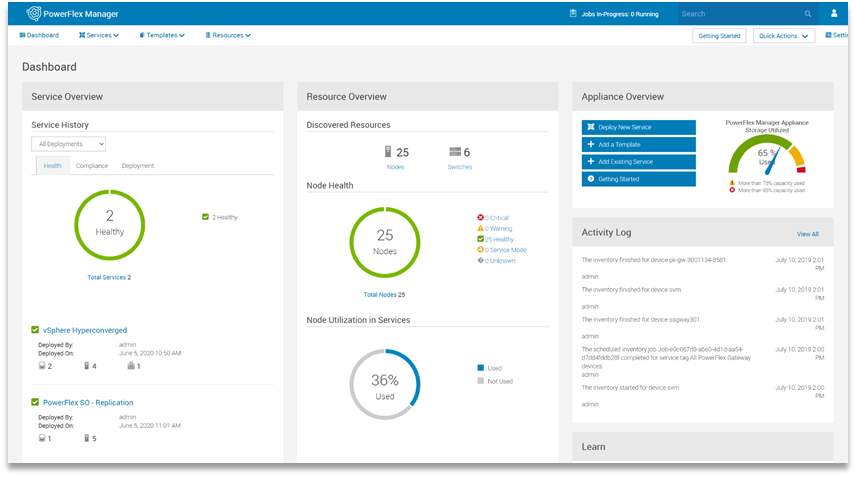
The resulting unique architecture of the PowerFlex family easily meets the large-scale, always-on requirements of our customers’ core enterprise applications. The power and resiliency of the PowerFlex infrastructure platforms handle everything from high-performance enterprise databases, to web-scale transaction processing, to demanding business solutions in various industries including healthcare, utilities and energy. And this includes the new big-data and analytical workloads that are quickly augmenting the core applications as the business processes are being transformed.
PowerFlex: A Unique Platform for Operating and Transforming Critical Applications
 PowerFlex provides the flexibility to utilize your choice of tools and solutions to drive your transformation and consolidation, while controlling the costs of the relentless expansion in data processing. PowerFlex provides the modularity to adapt and grow efficiently while providing the manageability to simplify your operations and reduce costs. It provides the scalable infrastructure on-premises to allow you focus on your business operations. PowerFlex on-demand options by the end of 2020 enable an elastic OPEX consumption model as well.
As your business needs change, PowerFlex provides a non-disruptive path of adaptability. As you need more compute, storage or application workloads, PowerFlex modularly expands without complex data migration services. As your application infrastructure needs change from virtualization to containers and bare metal, PowerFlex can mix and match these in any combination necessary without needing physical changes or cluster segmentation. PowerFlex provides future-proof capabilities that keep up with your demands with six nines of availability and linear scalability.
With the dynamic new pace of growth and change, PowerFlex can ensure you stay in charge while enabling the agility to adapt efficiently. PowerFlex enables you to leverage the advantages of oversight and cost-effectiveness of the on-premises environment with the ability to meet transformation head-on.
For more information, see PowerFlex on Dell EMC.com, or reach out to Contact Us.
footnotes:
1 IDC Cloud Repatriation Accelerates in a Multi-Cloud World, July 2018
2 451 Research, 2020 Voice of the Enterprise
3 IDC FutureScape: Worldwide Enterprise Infrastructure 2020 Predictions, October 2019

PowerFlex Native Asynchronous Replication RPO with Oracle
Tue, 18 Aug 2020 17:07:05 -0000
|Read Time: 0 minutes
PowerFlex software-defined storage platform provides a reliable, high-performance foundation for mission-critical applications like Oracle databases. In many of these deployments, replication and disaster recovery have become a common practice for protecting critical data and ensuring application uptime. In this blog, I will be discussing strategies for replicating mission-critical Oracle databases using Dell EMC PowerFlex software-defined storage.
The Role of Replication and Disaster Recovery in Enterprise Applications
Customers require Disaster Recovery and Replication capabilities to meet mission-critical business requirements where SLAs require the highest uptime. Customers also want the ability to quickly recover from physical or logical disasters to ensure business continuity in the event of disaster and be able to bring up the applications in minimal time without impact to data. Replication means that the same data is available at multiple locations. For Oracle database environments, it is important to have local and remote replicas of application data which are suitable for testing, development, reporting, and disaster recovery and many other operations. Replication improves the performance and protects the availability of Oracle database application because the data exists in another location. Advantages of having multiple copies of data being present across geographies is that, critical business applications will continue to function if the local Oracle database server experiences a failure.
Replication enables customers in various scenarios such as:
- Disaster Recovery for applications ensuring business continuity
- Distributing with one type of use case such as analytics
- Offloading for mission-critical workloads such as BI, Analytics, Data Warehousing, ERP, MRP, and so on
- Data Migration
- Disaster Recovery testing
PowerFlex Software-Defined Storage – Flexibility Unleashed
PowerFlex is a software-defined storage platform designed to significantly reduce operational and infrastructure complexity, empowering organizations to move faster by delivering flexibility, elasticity, and simplicity with predictable performance and resiliency at scale. The PowerFlex family provides a foundation that combines compute as well as high performance storage resources in a managed unified fabric.
PowerFlex is designed to provide extreme performance and massive scalability up to 1000s of nodes. It can be deployed as a disaggregated storage / compute (two-layer), HCI (single-layer), or a mixed architecture. PowerFlex inclusively supports applications ranging from bare-metal workloads and virtualized machines to cloud-native containerized apps. It is widely used for large-scale mission-critical applications like Oracle database. For information about best practices for deploying Oracle RAC on PowerFlex, see Oracle RAC on PowerFlex rack.
PowerFlex also offers several enterprise-class native capabilities to protect critical data at various levels:
- Storage Disk layer: PowerFlex storage distributed data layout scheme is designed to maximize protection and optimize performance. A single volume is divided into chunks. These chunks will be striped on physical disks throughout the cluster, in a balanced and random manner. Each chunk has a total of two copies for redundancy.
- Fault Sets: By implementing Fault sets, we can ensure the persistent data availability at all time. PowerFlex (previously VxFlex OS) will mirror data for a Fault Set on SDSs that are outside the Fault Set. Thus, availability is assured even if all the servers within one Fault Set fail simultaneously. Fault Sets are subgroup of SDSs installed on host servers within a Protection Domain.
PowerFlex replication overview
PowerFlex software consists of a few important components - Meta Data Manager (MDM), Storage Data Server (SDS), Storage Data Client (SDC) and Storage Data Replicator (SDR). MDM manages the PowerFlex system as a whole, which includes metadata, devices mapping, volumes, snapshots, system capacity, errors and failures, system rebuild and rebalance tasks. SDS is the software component that enables a node to contribute its local storage to the aggregated PowerFlex pool. SDC is a lightweight device driver that exposes PowerFlex volumes as block devices to the applications and hosts. SDR handles the replication activities. PowerFlex has a unique feature called Protection Domain. A Protection Domain is a logical entity that contains a group of SDSs. Each SDS belongs to only one Protection Domain.
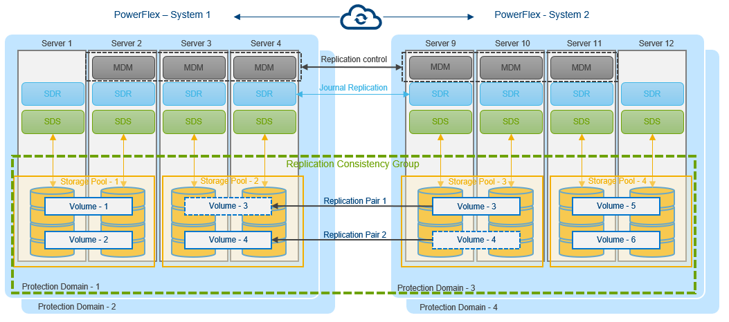
Figure 1. PowerFlex asynchronous replication between two systems
Replication occurs between two PowerFlex systems designated as peer systems. These peer systems are connected using LAN or WAN and are physically separated for protection purposes. Replication is defined in scope of a protection domain. All objects which participate in replication are contained in the protection domain, including volumes in Replication Consistency Group (RCG). Journal capacity from storage pools in the protection domain is shared among RCGs in the protection domain.
The SDR handles replication activities and manages I/O of replicated logical volumes. The SDR is deployed on the same server as SDS. Only I/Os from replicated volumes flows through SDR.
Replication Data Flow
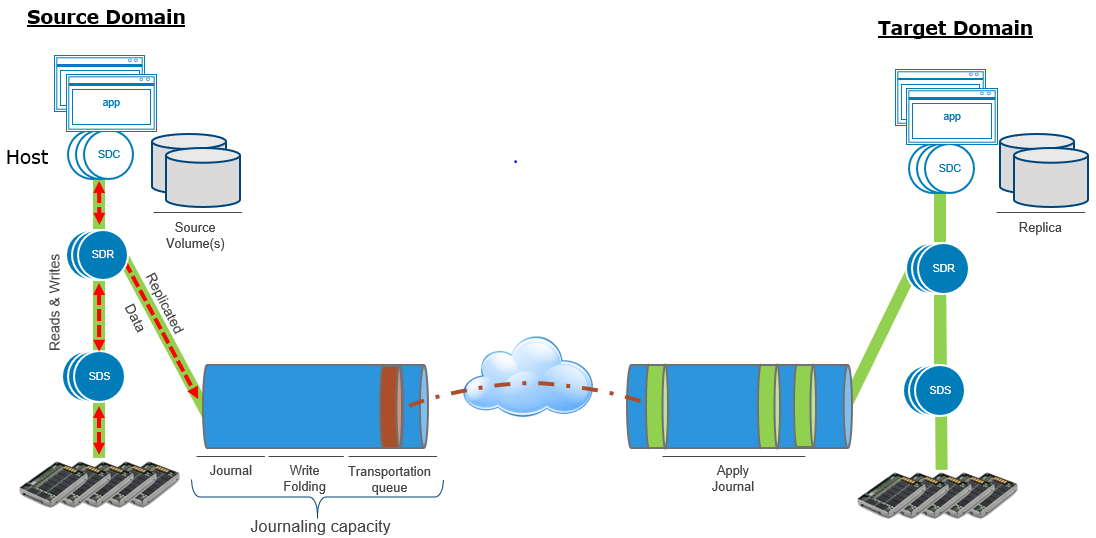
Figure 2. PowerFlex replication I/O flow between two systems
- At the source, application I/O are passed from SDS to SDR.
- Application I/O are stored in the source journal space before it is sent to target. SDR packages I/O in bundles and sends them to the target journal space.
- Once the I/O are sent to target journal and get placed in target journal space, they are cleared from source.
- Once I/O are applied to target volumes, they are cleared from destination journal.
- For replicated volumes, SDS communicates to other SDS via SDR. For non-replicated volumes, SDS communicates directly with other SDS.
For detailed information about Architecture Overview, see Dell EMC PowerFlex: Introduction to Replication White Paper.
It is important to note that this approach to replication allows PowerFlex to support replication at extreme scales. As the number of nodes contributing storage are scaled, so are the SDR instances. As a result, this replication mechanism can scale effortlessly from 4 to 1000s of nodes while delivering RPOs as low as 30 seconds and meeting IO and throughput requirements.
Oracle Databases on PowerFlex
The following illustration demonstrates that the volumes participating in replication are grouped to form the Replication Consistency Group (RCG). RCG acts as the logical container for the volumes.
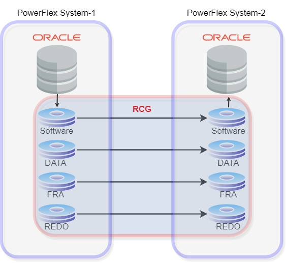
Figure 3. PowerFlex replication with Oracle database
Depending on the scenario, we can create multiple RCGs for each volume pair or combine multiple volume pairs in a single RCG.
In the above Oracle setup, PowerFlex System-1 is the source and PowerFlex System-2 is the destination. For replication to occur between the source and target, the following criteria must be met:
- A volume pair must be created in both source and target.
- Size of volumes in both source and target should be same. However, the volumes can be in different storage pools.
- Volumes are in read-write access mode on the source and read-only access mode in secondary. This is done to maintain data integrity and consistency between two peer systems.
The PowerFlex replication is designed to recover from as low as a 30 seconds RPOs minimizing the data-loss if there is a disaster recovery. During creation of RCG, users can specify RPO starting from 30 seconds to maximum of 60 minutes.
All the operations performed on source will be replicated to destination within the RPO. To ensure RPO compliance, PowerFlex replicates at least twice for every RPO period. For example, setting RPO to 30 seconds means that PowerFlex can immediately return to operation at the target system with only 30 seconds of potential data loss.
The following figures depicts the replication scenario under steady state of workload:
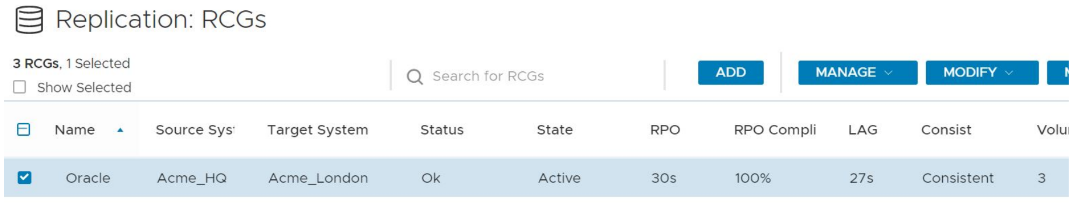
Figure 4. 100% RPO compliance for RPO of 30s for an Oracle database during a steady application workload
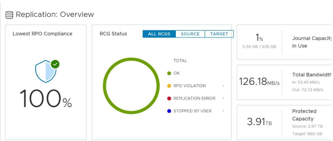
Figure 5. Replication dashboard view of PowerFlex
Disaster Recovery
In the case of disaster recovery, the entire application can be up and running by failover to secondary, with less than 30 seconds of data loss.
When we do a planned switchover or failover, the volumes on secondary system are automatically changed to read-write access mode and the volumes on source will be changed to read-only. Consequently, we can bring up Oracle database on secondary by setting up the Oracle environment variables and starting the database.
Once we have RCG in the failover or switchover mode, user can decide how to continue with replication:
- Restore replication: Maintains the replication direction from original source to destination.
- Reverse replication: Changes the direction so that original destination becomes the source and replication will begin from original destination to original source.
PowerFlex also provides various other options:
- Pause and Resume RCG: If there are network issues or user need to perform maintenance of any of the hardware. While paused, any application I/O will be stored at source journal and is replicated to the destination only after the replication is resumed.
- Freeze and Unfreeze RCG: If the user requires consistent snapshot of the source or target volumes. While frozen, replication will still occur between source journal and destination journal, nonetheless the target journal holds on to the data and do not apply them to the target volumes.
PowerFlex native volume replication is a unique solution and provides customers with easy to configure and setup without worrying about disaster.
Irrespective of workload and application, it is designed to support massive scale while providing RPOs as low as 30 seconds.
For more information, please visit: DellTechnologies.com/PowerFlex.

Grace Under Pressure — PowerFlex Rebuild Superpowers
Wed, 27 Jan 2021 12:30:14 -0000
|Read Time: 0 minutes
The first blog in this series, “Resiliency Explained — Understanding PowerFlex's Self-Healing, Self-Balancing Architecture,” covered an overview of how the PowerFlex system architecture provides superior performance and reliability. Today, we’ll take you through another level of detail with specific examples of recoverability.
Warning: Information covered in this blog may leave you wanting for similar results from other vendors.
PowerFlex possess some incredible superpowers that deliver performance results that run some of the world’s most demanding applications. But what happens when you experience an unexpected failure like losing a drive, a node, or even a rack of servers? Even planned outages for maintenance can result in vulnerabilities or degraded performance levels, IF you use conventional data protection architectures like RAID.
Just a reminder, PowerFlex is a high-performance software defined storage system that delivers the compute and storage system in a unified fabric with the elasticity to scale either compute, storage or both to fit the workload. PowerFlex uses all-flash direct attached media located on standard x86 servers utilizing industry standard HBA adapters and 10 Gb/s or higher ethernet NICs that interconnect servers. The systems scale from 4 nodes to multi-rack 1000+ nodes while increasing capacity, linearly increasing IOPS, all while sustaining sub-millisecond latency.
Powerful Protection
PowerFlex takes care of dynamic data placement that ensures there are NO hot spots, so QoS is a fundamental design point and not an after-thought bolt-on “fix” for a poor data architecture scheme; there’s no data locality needed. PowerFlex handles the location of data to ensure there are no single points of failure, and it dynamically re-distributes blocks of data if you lose a drive, add a node, take a node off line, or have a server outage (planned or unplanned) containing a large number of drives. It automatically load balances the placement of data as storage use changes over time or with node expansion.
The patented software architecture underlying PowerFlex doesn’t use a conventional RAID protection mechanism. RAID serves a purpose, and even options like erasure coding have their place in data protection. What’s missing in these options? Let’s use a couple of analogies to compare traditional RAID and PowerFlex protection mechanisms:
RAID
Think of RAID as a multi-cup layout where you’re looking to ensure each write places data in multiple cups. If you lose a cup, you don’t necessarily re-arrange the data. You’re protected from data loss, but without the re-distribution, you’re still operating in a deprecated state and potentially vulnerable to additional failures until the hardware replacement occurs. If you want more than one level of cup failure, you have multiple writes to get multiple cups which creates more overhead (particularly in a software-defined storage versus a hardware RAID controller-based system). It still only takes care of data protection and not necessarily performance recovery.
PowerFlex
Think of the architectural layout of data like a three-dimensional checkerboard where we ensure the data placement keeps your data safe. In the checkerboard layout, we can quickly re-arrange the checkers if you lose a box on the board or a row/column or even a complete board of checkers. Re-arranging the data to ensure there’s always two copies of the data for on-going protection and restoration of performance. The three-dimensional aspect comes from all nodes and all drives participating in the re-balancing process. The metadata management system seamlessly orchestrates re-distribution and balancing data placement.
Whether the system has a planned or unplanned outage or a node upgrade or replacement, this automatic rebalancing happens rapidly because every drive in the pool participates. The more nodes and the more drives, the faster the process of reconstituting any data rebuilding processes. In the software defined PowerFlex solution there’s no worrying about a RAID level or the performance trade-offs, it’s just taken care of for you seamlessly in the background without any of the annoying complications RAID often introduces or the need any specialized hardware controllers and associated cost.
Results
Drive Rebuild
PowerFlex looks at actual data stored on each drive rather than treating the whole drive capacity as what needs recovering. In this example, a drive failure occurs. The data levels illustrated here represent the total used capacity in these 6, 9 or 12 node configuration examples (we can scale to over 1,000 nodes). The 25%, 50% and 75% levels show relative rebuild times for this 960GB SAS SSD to return to restore the data to a full heathy state (re-protected).
We’re showing you a rebuild scenario to emphasize the performance, but taking it to another level, you wouldn’t be urgently needing to replace the drive as we leverage the data redistribution to other drives for protection and sustaining performance while using virtual spare space provided by all of the drives to pick up the gap. Unlike RAID, we don’t need to replace the drive to return the system to full health. You can replace the drive when it’s convenient.
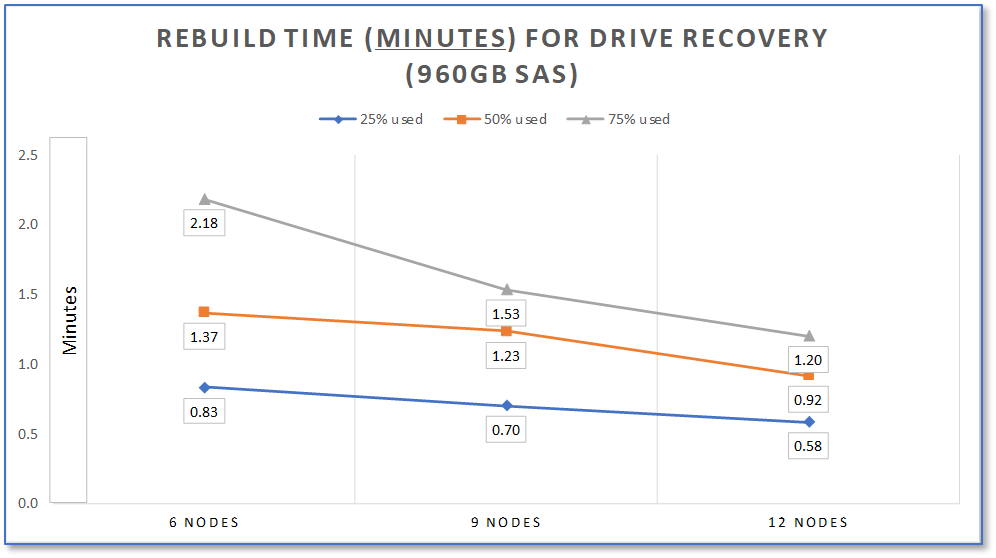
Notice a few things:
- More nodes = less rebuild time! Try this if you scale out alternative options and I think you’ll find the inverse.
- The near linear rebuild performance improves as you add more drives and nodes. Imagine if this showed even more nodes participating in the rebuild process!
- More data density doesn’t result in a linear increase in the rebuild time. As you see in the 12-node configuration, it starts to converge on a vanishing point.
This illustrates what happens when you have 35, 53, and 71 drives participating in the parallel rebuild process for the six, nine and twelve node configurations, respectively.
Node Rebuild (6 drives)
Here we show an example using a similar load level of data on the nodes. The nodes each contain six drives with a maximum of 5.76TB to be rebuilt. The entire cluster of drives participates in taking over the workloads, automatically rearranging the data placement and making sure the cluster always has two copies of the data residing on different nodes. Just as in the above drive rebuild example, the process leverages all the remaining drives from the cluster to take on the rebuild process to return to a fully protected state. That means for the six-node configuration there are 30 drives participating in the parallelized rebuild, 48 drives in the nine-node configuration and 66 drives in the twelve nodes.
Notice again the near linear improvement in rebuild times as you increase the number of nodes and drives. As in the drive rebuild scenario, the node rebuild time observed also tends to approach a vanishing point for the varying data saturation levels.
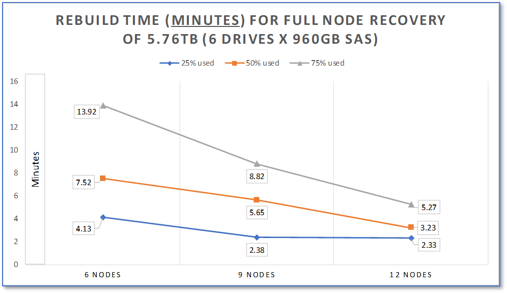
As mentioned previously, PowerFlex scales to 1000+ nodes. Take a scenario where you need to affect an entire rack of servers and remain operational and recoverable (unthinkable in conventional architectures) and you see why our largest customers depend on PowerFlex.
Testing Details
If the above tests were done just to show off the best rebuild times, we would just run these systems without any actual other work occurring. However, that wouldn’t reflect a real-world scenario where the intention is to continue operating gracefully and still recover to full operational levels.
These tests were done with the PowerFlex default rebuild setting of one concurrent I/O per drive. For customers with more aggressive needs to return to fully protected, PowerFlex can be configured to accelerate rebuilds as a priority. To optimize rebuilds even more than illustrated, you can set the number of concurrent I/Os per drive to two or more or even unlimited. Since changing the number of I/Os per drive does affect latency and IOPS, which could adversely impact workloads, we chose to illustrate our default example that intentionally balances keeping workload performance high while doing the rebuild.
Using FIO* as a storage I/O generator, we ran these rebuild scenarios with ~750k random IOPS of activity on the 12 node configuration, ~600k random IOPS on the 9-nodes and ~400k on the 6-nodes, all while sustaining 0.5mS latency levels (cluster examples here can drive well over 1M IOPS at sub-mS levels). This represents a moderately heavy workload operating while we performed these tests. Even with the I/O generator running and the rebuild process taking place, the CPU load was approximately 20%. The I/O generator alone only consumed 8 to 10% of the available CPU capacity. Both CPU utilization figures underscores the inherent software defined infrastructure efficiency of PowerFlex that leaves a lot of available capacity to host application workloads. In this test case scenario, both the compute and storage occupied the same node (hyperconverged), but remember that we can also run a in 2-layer configuration using compute only and storage only nodes for asymmetrical scaling.
The systems used for these tests had the following configuration. Note that we used six drives per node in the R740xd chassis that can hold 24 drives, which means there were another 18 slots available for additional drives. As noted previously, more drives mean more parallel capabilities for performance and rebuild velocity.
- 12x R740xd nodes with 2 sockets Intel Xeon Gold 2126 2.6Ghz (12 cores /socket)
- Six had 256GB RAM & six utilized 192GB RAM
Conclusion
PowerFlex delivers cloud scale performance with unrivaled grace under pressure reliability for delivering a software defined block storage product with six nines of availability. Be sure to read Part 1 of this blog “Resiliency Explained — Understanding PowerFlex's Self-Healing, Self-Balancing Architecture” to see the other protection architecture elements not covered here. For more information on our validated mission critical workloads like Oracle RAC, SAP HANA, MySQL, MongoDB, SAS, Elastic, VDI, Cassandra and other business differentiating applications, please visit our PowerFlex product site.
Footnotes
* FIO set for 8k, 20% random write, 80% random reads

Resiliency Explained — Understanding the PowerFlex Self-Healing, Self-Balancing Architecture
Mon, 17 Aug 2020 21:36:11 -0000
|Read Time: 0 minutes
My phone rang. When I picked up it was Rob*, one of my favourite PowerFlex customers who runs his company’s Storage Infrastructure. Last year, his CTO made the decision to embrace digital transformation across the entire company, which included a software-defined approach. During that process, they selected the Dell EMC PowerFlex family as their Software-Defined Storage (SDS) infrastructure because they had a mixture of virtualised and bare-metal workloads, needed a solution that could handle their unpredictable storage growth, and also one powerful enough to support their key business applications.
During testing of the PowerFlex system, I educated Rob on how we give our customers an almost endless list of significant benefits – blazingly fast block storage performance that scales linearly as new nodes are added to the system; a self-healing & self-balancing storage platform that automatically ensures that it always gives the best possible performance; super-fast rebuilds in the event of disk or node failures, plus the ability to engineer a system that will meet or exceed his business commitments to uptime & SLAs.
PowerFlex provides all this (and more) thanks to its “Secret Sauce” – its Distributed Mesh-Mirror Architecture. It ensures there are always two copies of your application data – thus ensuring availability in case of any hardware failure. Data is intelligently distributed across all the disk devices in each of the nodes within a storage pool. As more nodes are added, the overall performance increases nearly linearly, without affecting application latencies. Yet at the same time, adding more disks or nodes also makes rebuild times during those (admittedly rare) failure situations decrease – which means that PowerFlex heals itself more quickly as the system grows!
PowerFlex automatically ensures that the two copies of each block of data that gets written to the Storage Pool reside on different SDS (storage) nodes, because we need to be able to get a hold of the second copy of data if a disk or a storage node that holds the first block fails at any time. And because the data is written across all the disks in all the nodes within a Storage Pool, this allows for super-quick IO response times, because we access all data in parallel.
Data also gets written to disk using very small chunk sizes – either 1MB or 4KB, depending on the Storage Pool type. Why is this? Doing this ensures that we always spread the data evenly across all the disk devices, automatically preventing performance hot-spots from ever being an issue in the first place. So, when a volume is assigned to a host or a VM, that data is already spread efficiently across all the disks in all Storage Nodes. For example, a 4-Node PowerFlex system, with 3 volumes provisioned from it, will look something like the following:
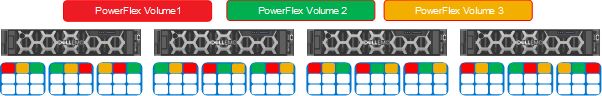
Figure 1: A Simplified View of a 4-Node PowerFlex System Presenting 3 Storage Volumes
Now, here is where the magic begins. In the event of a drive failure, the PowerFlex rebuild process utilizes an efficient many-to-many scheme for very fast rebuilds. It uses ALL the devices in the storage pool for rebuild operations and will always rebalance the data in the pool automatically whenever new disks or nodes are added to the Storage Pool. This means that, as the system grows, performance increases linearly – which is great for future-proofing your infrastructure if you are not sure how your system will grow. But this also gives another benefit – as your system grows in size, rebuilds get faster!
Customers like Rob typically raise their eyes at that last statement – until we provide a simple example to get the point across – and then they have a lightbulb moment. Think about what happens if we used a 4-node PowerFlex system, but only had one disk drive in each storage node. All data would be spread evenly across the 4 Nodes, but we also have some spare capacity reserved, which is also spread evenly across each drive. This spare capacity is needed to rebuild data into, in the event of a disk or a node failure and it usually equates to either the capacity of an entire node or 10% of the entire system, whichever is largest. At a superficial level, a 4-Node system would look something like this:
Figure 2: A Simplified View of a 4-Node PowerFlex System & Available Dataflows
If one of those drives (or nodes) failed, then obviously we would end up rebuilding between the three remaining disks, one disk per node:
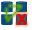
Figure 3: Our Simplified 4-Node PowerFlex System & Available Dataflows with One Failed Disk
Now of course, in this scenario, that rebuild is going to take some time to complete. We will be performing lots of 1MB or 4KB copies between the three remaining nodes, in both directions, as we rebuild into the spare capacity available on the remaining nodes & get back to having two copies of data in order to be fully protected again. It is worth pointing out here that a node typically contains 10 or 24 drives, not just one, so PowerFlex isn’t just protecting you from “a” drive failure, we’re able to protect you from a whole pile of drives. This is not your typical RAID card schema.
Now – let the magic of PowerFlex begin! What happens if we were to add a fifth storage node into the mix? And what happens when a disk or node fails in this scenario??
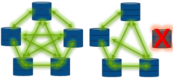
Figure 4: Dataflows in a Normally Running 5-Node PowerFlex System … & Available Dataflows with One Failed Disk or Node
It should be clear for all to see that we now have more disks - and nodes - to participate in the rebuild process, making the rebuild complete substantially faster than in our previous 4 node scenario. But PowerFlex nodes do not have just a single disk inside them - They typically have 10 or 24 drive slots, hence even for a small deployment with 4 nodes, each having 10 disks, we will have data placed intelligently and evenly across all 40 drives, configured as one Storage Pool. Now, with today’s flash media, that is a heck of a lot of performance capability available at your fingertips, that can be delivered with consistent sub-millisecond latencies.
Let me also highlight the “many-to-many” rebuild scheme used by each Storage Pool. This means that any data within a Storage Pool can be rebuilt to all the other disks in the same Pool. If we have 40 drives in our pool, it means that when one drive fails, the other 39 drives will be utilised to rebuild the data of the failed drive. This results in extremely quick rebuilds that occur in parallel, with minimum impact to application performance if we lose a disk:
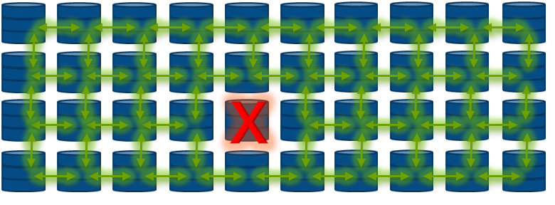
Figure 5: A 40-disk Storage Pool, with a Disk Failure… Showing The Magic of Parallel Rebuilds
Note that we had to over-simplify the dataflows between the disks in the figure above, because if we tried to show all the interconnects at play, we would simply have a tangle of green arrows!
Here’s another example to explain the difference between PowerFlex and conventional RAID-type drive protection. The initial rebuild test on an empty system usually takes little more than a minute for the rebuild to complete. This is because PowerFlex will only ever rebuild chunks of application data, unlike a traditional RAID controller, which will rebuild disk blocks whether they contain data or not. Why waste resources rebuilding empty zeroes of data when you need to repair from a failed disk or node as quickly as possible?
The PowerFlex Distributed Mesh-Mirror architecture is truly unique and gives our customers the fastest, most scalable and most resilient block storage platform available on the market today! Please visit www.DellTechnologies.com/PowerFlex for more information.
* Name changed to protect the innocent!

PowerFlex and CloudLink: A Powerful Data Security Combination
Mon, 17 Aug 2020 21:41:08 -0000
|Read Time: 0 minutes
Security and operational efficiency continue to top IT executives’ datacenter needs lists. Dell Technologies looks at the complete solution to achieve both so customers can focus on their business outcomes.
Dell Technologies’ PowerFlex is a software-defined storage platform designed to significantly reduce operational and infrastructure complexity, empowering organizations to move faster by delivering flexibility, elasticity, and simplicity with predictable performance and resiliency at scale. PowerFlex provides a unified fabric of compute and storage with scale out flexibility for either of these ingredients to match workload requirements with full lifecycle simplification provided by PowerFlex Manager. Dell Technologies’ CloudLink, data encryption and key management solution, supports workload deployments from edge to core to cloud, providing a perfect complement to the PowerFlex family that enables flexible encryption tailored to the modern datacenter’s needs.
With increasing regulatory and compliance requirements, more and more customers now realize how critical encryption is to securing their data centers and need solutions that are built into their platforms. CloudLink, integrated with PowerFlex, provides reliable data encryption and key management in one solution with the flexibility to satisfy most customer's needs.
Built-in, not bolt on
CloudLink’s rich feature set integrates directly into the PowerFlex platform allowing our customers access to CloudLink's encryption and key management functionality, including data at rest and data in motion encryption, full key lifecycle management, and lightweight multi-tenancy support.
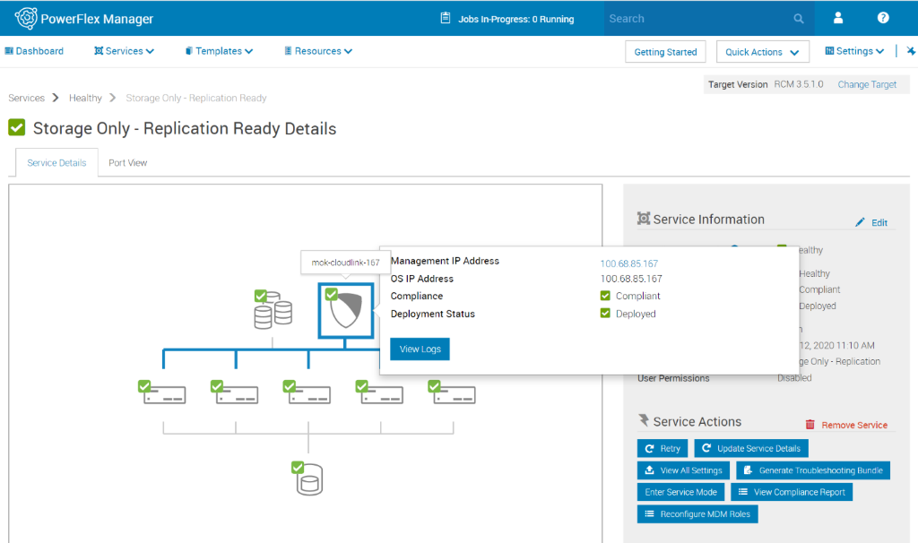
- Encryption for PowerFlex
CloudLink provides software-based data encryption and a full set of key management capabilities for PowerFlex, including:
- Policy-based key release to ensure data is only unlocked in a safe environment
- Machine grouping to ensure consistent policy configuration across drives
- Full key lifecycle management to maintain proper encryption key hygiene
- Key Management for Self-Encrypting Drives (SED)
SEDs offer high performant hardware-based Data-at-Rest Encryption ensuring that all data in the deployment is safe from prying eyes. On a PowerFlex platform, CloudLink can manage the keys for each individual drive and store them safely within our encrypted vault where customers can leverage CloudLink's full key lifecycle management feature set. This option, also integrated and deployable with PowerFlex Manager, is ideal for your sensitive data assets that require high-performance.
- Encryption for Machines
Sometimes Data-at-Rest Encryption is not enough, and our customers need to encrypt their virtual machines. CloudLink provides VM encryption by deploying agents on the guest OS. CloudLink's agent encryption gives our customers the ability to move encrypted VMs throughout their environment making tasks such as replication, deployment to production from QA, or out to satellite offices, safer and easier.
CloudLink’s encryption for machines agent can also encrypt data volumes on bare metal servers allowing customers to keep their data safe even when deployed on legacy hardware.
- Key Management over KMIP
When 3rd party encryptors need external key management, they turn to solutions that implement KMIP (Key Management Interoperability Protocol). This open standard defines how encryptors and key managers communicate. CloudLink implements the KMIP protocol both as a client and a server to provide basic key storage and management for encryptors such as VMware’s native encryption features, or to plug-in to a customer’s existing keystore. These capabilities provide the flexibility required for today’s heterogenous environments.
Supporting the modern datacenter
There is a sea change occurring in data centers brought on by the relatively new technology of containers. 451 Research, a global research and advisory firm, released the results of its 2020 Voice of the Enterprise survey, which indicates that as companies consider the move to containerized deployments, security and compliance concerns are top of mind. However, for so many of the new container technology products from which to choose, proper security is not built-in.
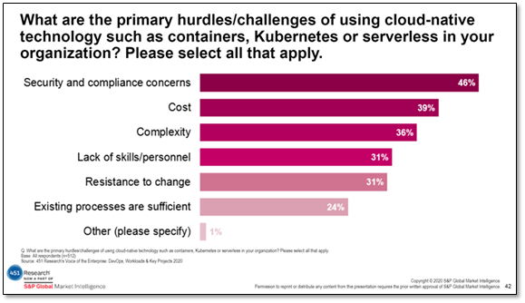
Given the extreme mobility of containers, keeping customers’ data safe as applications move throughout a deployment – especially within the cloud – is a challenge. To address this gap, we introduced file volume encryption for Kubernetes container deployments in our CloudLink 7.0 release, which has been validated with PowerFlex 3.5. Our container encryption functionality is built on the same full lifecycle key management and agent-based encryption architectural model that we currently offer for PowerFlex. We deploy an agent within the container such that it sits directly on the data path. As the data is saved, we intercept it and make sure it is encrypted as it travels to and then comes to rest in the data store.
Data security doesn’t need to mean complex management
Hand in hand with PowerFlex, CloudLink provides data encryption and key management with unmatched flexibility, superior reliability, and simple and efficient operations complete with support from Dell as a complete solution. The PowerFlex Manager is a comprehensive IT operations and lifecycle management tool that drastically simplifies management and ongoing operation. CloudLink is integrated into this tool to make the deployment of the CloudLink agent a natural part the PowerFlex management framework.
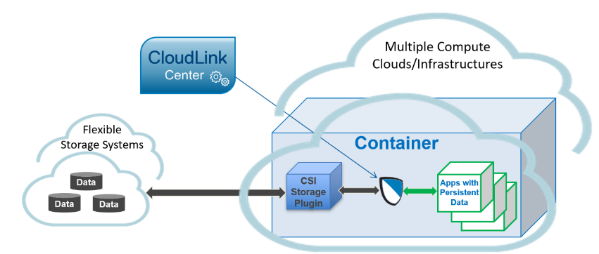
Are you interested in PowerFlex and CloudLink? Please visit our websites for PowerFlex or CloudLink or reach out to your Dell Technologies sales representative for help.
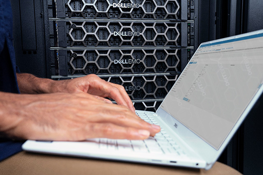
PowerFlex: The advantages of disaggregated infrastructure deployments
Mon, 17 Aug 2020 21:39:26 -0000
|Read Time: 0 minutes
For several years, there has been a big push from quite a number of IT vendors towards delivering solutions based on Hyperconverged Infrastructure or HCI. The general concept of HCI is to take the three primary components of IT, compute, network and storage, and deliver them in a software defined format within a building block, normally an x86 based server. These building blocks are then joined together to create a larger, more resilient environment. The software defined components are typically a hypervisor to provide compute, virtual adapters and switches for networking, along with some software that takes the local disks attached to the server, combines them with the disks directly attached to the other building blocks and presents them as a virtual storage system back to the environment.
The HCI approach is attractive to customers for a variety of reasons:
- Easy upgrades by just adding in another building block
- A single management interface for virtual compute, virtual networking and virtual storage
- Having one team to manage everything as it is all in one place
There are of course scenarios where the HCI model does not fit, the limitations are frequently associated with the software defined storage part of the environment, situations such as the following:
- Extra storage is required but additional compute and the associated licensing is not.
- Paying for database licensing on cores that are being used for virtual storage processes.
- Unused storage capacity within the HCI environment that is inaccessible to servers outside the HCI environment.
- A server requirement for a specific workload that does not match the building blocks deployed.
- When maintenance is required it impacts both compute and storage.
Several HCI vendors have attempted to address these points but often their solutions to the issues involve a compromise.
What if there was a solution that provided software defined storage that was flexible enough to meet these requirements without compromise?
Step forward PowerFlex, a product flexible enough to be deployed as an HCI architecture, a disaggregated architecture (separate compute and storage layers managed within the same fabric), or a mixture of the two.
So how can PowerFlex be this flexible?
It is all about how the product was initially designed and developed, it consists predominantly of three separate software components:
- Storage Data Client (SDC): The software component installed on the operating system that will consume storage. It can be thought of as analogous to a Fibre Channel adapter driver from the days of SAN interconnect storage arrays. It can be installed on a wide selection of operating systems and hypervisors, most Linux distributions, VMware and Windows are supported.
- Storage Data Server (SDS): The component that is installed on the server or virtual server providing local disk capacity, it works with other servers installed with the SDS software to provide a pool of storage from which volumes are allocated. It is generally installed on a Linux platform.
- Metadata Manager (MDM): The software management component, it ensures that SDC and the SDS components are behaving themselves and playing nicely together (parents of more than one child will understand).
Each of these components can be installed across a cluster of servers in a variety of ways in order to create flexible deployment scenarios. The SDC and SDS components communicate with one another over a standard TCP/IP network to form an intelligent fabric, this is all overseen by the MDM, which is not in the data path.
Some pictures will help illustrate this far better than I can with words.
By installing the SDC (the C in a yellow box) and the SDS (the S in a green box) on to the same server, an HCI environment is created.
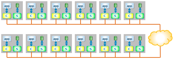
If the SDC and SDS are installed on dedicated servers, a disaggregated infrastructure is created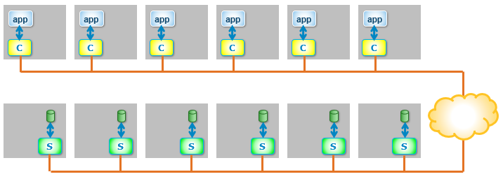
And because PowerFlex is entirely flexible (the clue is in the name), HCI and disaggregated architectures can be mixed within the same environment.
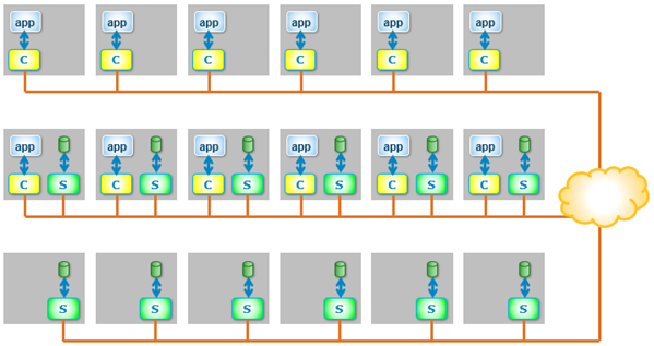
What are the advantages of deploying a disaggregated environment?
- MAXIMUM FLEXIBILITY - Compute and storage resources can be scaled independently.
- CLOUD-LIKE ECONOMICS – following on from above – what if an application needs to cope with a sudden doubling of compute resource (for example, to cope with a one-off business event)? With a disaggregated deployment, the extra compute-only resources can be added temporarily into the environment, ride the peak demand, then retire afterwards, reducing expenditure by only using what is needed.
- MAXIMISE STORAGE UTILISATION - Completely heterogeneous environments can share the same storage pool.
- CHOOSE THE CORRECT CPU FOR THE WORKLOAD - Servers with frequency optimised processors can be deployed for database use and not require licenses for cores potentially performing processing related to storage.
- AVOID CREATING MULTIPLE ISLANDS OF SOFTWARE DEFINED STORAGE - A mixture of hypervisors and operating systems can be deployed within the same environment; VMware, Hyper-V and Red Hat Virtualisation, along with operating systems running on bare metal hardware, all accessing the same storage.
- UPDATE STORAGE & COMPUTE INDEPENDENTLY - Maintenance can be performed on storage nodes completely independently of compute nodes and vice versa, thereby simplifying planned downtime. This can dramatically simplify operations, especially on larger clusters and prevents storage and compute operators from accidentally treading on each other’s toes!
Whilst HCI deployments are ideal for environments where compute requirements and storage capacity increases remain in lockstep, there are many use cases where compute and storage needs grow independently, PowerFlex is capable of serving both requirements.
PowerFlex was built to allow this disaggregation of resources from day one, which means that there is no downside to performance or capacity when storage nodes are added to existing clusters, in fact there are only positives, with increased performance, capacity and resilience, setting PowerFlex apart from many other software defined storage products.

Dell EMC PowerFlex and VMware Cloud Foundation for High Performance Applications
Tue, 04 Jul 2023 09:44:35 -0000
|Read Time: 0 minutes
The world in 2020 has shown all industries that innovation is necessary to thrive in all conditions. VMware Cloud Foundation (VCF) hybrid cloud platform was crafted by innovators who realize the biggest asset our customers have is their information technology and the data that runs the business. The VCF offering takes the complexity out of operationalizing infrastructure to enable greater elasticity, growth, and simplification through improved automation. VCF enables options available using on-premises and multi-cloud deployments to address ever changing enterprise needs.
VMware included design factors that anticipated customers’ use of varying storage options in the flexibility of implementing VCF. VMware vSAN is the standard for VCF hyperconverged infrastructure (HCI) deployments and is directly integrated into vSphere and VCF. For those circumstances where workloads or customer resource usage require alternative storage methods, VMware built flexibility into the VCF storage offering. Just as we see a wide variety in desktop computing devices, one size doesn't fit all applies to the enterprise storage products as well. Dell Technologies’ PowerFlex (formerly VxFlex) provides a software-defined mechanism to add a combination of compute and storage with scale out flexibility. As customers look to software-defined operational constructs for agility, PowerFlex provides an adjustable means to add the right balance of storage resources while enabling non-disruptive additions without painful migrations as demands increase.
Joining the Dell Technologies Cloud family as a validated design, Dell EMC PowerFlex helps customers simplify their path to hybrid cloud by combining the power of Dell EMC infrastructure with VMware Cloud Foundation software as supplemental storage. As a high-performance, scale out, software-defined block storage product, PowerFlex provides a combination of storage and compute in a unified fabric that's well equipped to service particularly challenging workloads. The scalability of compute and/or storage in a modular architecture provides an asymmetrical (2-layer) option to add capacity to either compute or storage independently. PowerFlex makes it possible to transform from a traditional three-tier architecture to a modern data center without any trade-offs between performance, resilience or future expansion.
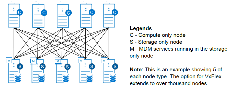
PowerFlex significantly reduces operational and infrastructure complexity, empowering organizations to move faster by delivering flexibility, elasticity, and simplicity with predictable performance and resiliency at scale for deployments. PowerFlex Manager is a key element of our engineered systems providing a full lifecycle administration experience for PowerFlex from day 0 through expansions and upgrades which is independent, but complementary to the full stack life cycle management available through VCF via SDDC Manager. A cornerstone value proposition of VCF is administering the lifecycle management of OS upgrades, vSphere updates, vRealize monitoring, automation and NSX administration. PowerFlex manager works in parallel with VCF to deliver a comprehensive lifecycle experience for the physical ingredients and for the PowerFlex software-define storage layer. PowerFlex also offers a vRealize Operations plug-in for a unified monitoring capability from VMware vRealize Suite which is included in most VCF editions. From a storage management perspective, PowerFlex utilizes a management system that complements VCF and VMware vSphere by working within the appropriate vCenter management constructs. PowerFlex Manager provides the administration of PowerFlex storage functions, while VCF and vCenter manages the allocation of LUNs to provisioned VMFS file systems to provide data stores for the provisioned workloads.
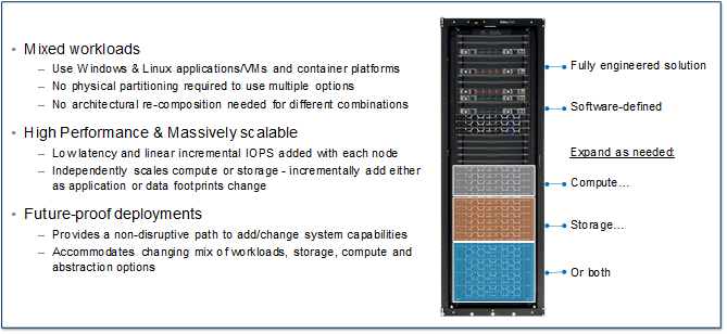
PowerFlex systems enables customers to scale from a small environment to enterprise scale with over a thousand nodes. In addition, it provides enterprise grade data protection, multi-tenant capabilities, and add-on enterprise features such as QoS, thin provisioning, compression and snapshots. PowerFlex systems deliver the performance and time-to-value required to meet the demands of the modern enterprise data center.
Does Supplemental Storage Mean Slow or Light Workload Use Cases?
PowerFlex provides a Dell Technologies validated design as a supplemental storage platform for VCF, unlocking the value of PowerFlex to be realized by customers within the VCF environment. By providing sub-millisecond latency, high IOPS and high throughput with linearity as nodes join the fabric, the result is a very predictable scaling profile that accelerates the VCF vision within the datacenter.
PowerFlex, as a part of VCF, can help solve for even the most demanding of applications. Using the supplemental capabilities to service workloads with the highest of efficiency provides a best of class performance experience. Some illustrative examples of demanding application workloads validated with PowerFlex, independent of VCF, include the following:
SAP HANA
SAP HANA certified for PowerFlex integrated rack in both 4-socket and 2-socket offerings (certification details). Highly efficient in hosting up to six production HANA instances per 4-socket server. Our capabilities outperform external competitors by hosting 2x the capacity. The Configuration and Deployment Best Practices for SAP HANA white paper provides details. While this white paper illustrates a single layer architecture, even better performance characteristics are achievable using the VCF aligned 2-layer architectural implementation of PowerFlex.
Oracle RAC & Microsoft SQL
Flexibility to run compute and storage on separate hardware results in significant reduction of database licensing cost.
- Oracle RAC Solution – Get over 1 Million IOPs with less than 1ms latency with Oracle 12c RAC database transactions in just six nodes delivering 33GB/sec throughput (5.6GB/sec per node).
- Oracle 19c RAC TPC-C achieving more than 10 Million TPMs in eight nodes.
- MS SQL 2019 Solution (white paper) or MS SQL 2019 Big Data Cluster with Kubernetes (white paper) delivering approximately 9 Million SQL Server transactions (TPMs) with less than 1ms latency using just five storage nodes.
SAS Analytics
Validated/certified by SAS for running SAS mixed analytics workloads (white paper) providing an average throughput of 210 MBs per core (40% greater than their recommended 150 MB/sec needed for certification).
Elastic Stack
The validated solution with Elastic provides customers with the required high-performance, scalable, block-based IO with flexible deployment options in multiple operating environments (Windows, Linux, Virtualized/Bare Metal). Elastic validated the efficiency of PowerFlex using only three compute and 4 storage nodes to deliver ~1 billion indexing events measured by Elastic’s Rally benchmarking tool.
EPIC
The validated PowerFlex solution for Epic delivers 6x9’s availability and high performance for critical the EPIC hyperspace workloads while simultaneously enabling hosting the VDI with the operational and analytical databases for a completely integrated infrastructure option.
Cassandra
For customers deploying Kubernetes container-based database deployments like Cassandra, PowerFlex provides 300,000 operations/second for 10 million operations (Read intensive operations) with avg read latency of 1ms on just eight nodes.
PowerFlex gives Dell Technologies the ability to help customers address diverse infrastructure needs. The implementation guide for using PowerFlex for supplemental storage provides the simple steps to provide complementary storage options for VCF deployments. For more information on the PowerFlex product family and workload solutions, please see the product page here.
Other pre-tested Dell Technologies Storage products validated for VMware Cloud Foundation that provide the capabilities to independently scale storage and compute include the offerings below. You can find more details in the Dell Technologies Cloud Validated Designs document.