What’s New in PowerFlex 4.0 REST API?
Mon, 08 May 2023 18:14:08 -0000
|Read Time: 0 minutes
Wow, it’s been a busy year for PowerFlex! It started with the major announcement of PowerFlex on AWS at Dell Technologies World 2022. Then, in late summer of 2022 we announced a major update in PowerFlex v4.0. PowerFlex v4.0 added NVMe/TCP support, File Storage services, and a new management & operations (M&O) stack called unified PowerFlex Manager. In September of 2022 the PowerFlex Solutions team released the Dell Validated Platform for Red Had OpenShift on PowerFlex.
Many of the enhancements solidify PowerFlex’s position as the ultimate infrastructure platform. One such improvement is with the REST API which is the topic of this blog. If you are new to REST API and are looking for a quick introduction, I suggest you start by reading the blog Getting Started with REST API by Florian and Parasar. With that base of understanding, let’s take a closer look at the improvements made to REST API in PowerFlex 4.0.
Single endpoint
The improvements made to the REST API that I cover here are part of the new unified PowerFlex Manager application. The following figure shows the PowerFlex management plane prior to PowerFlex 4.0. As you can see, the management plane differs by the consumption model. Here there are two REST API endpoints: the PowerFlex Gateway endpoint and the PowerFlex Manager endpoint.
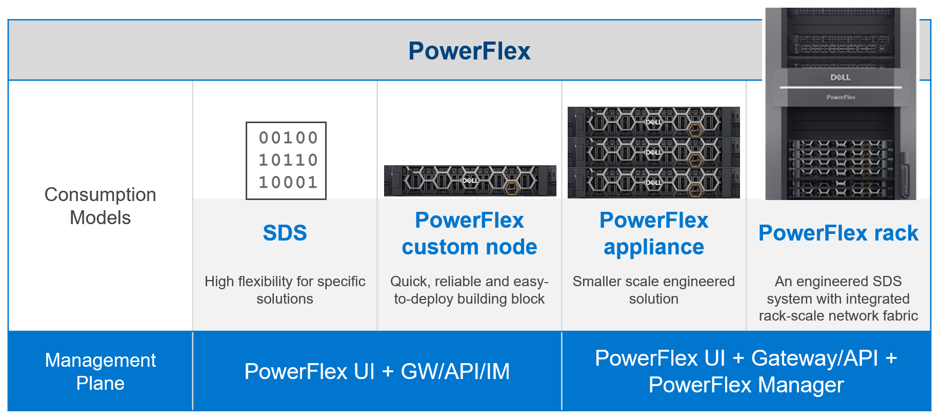
Figure 1. The PowerFlex Management Plane before 4.0
The PowerFlex Gateway endpoint provides access to block management and installation manager functions for all consumption models. The PowerFlex Manager endpoint provides access to lifecycle management functions for rack and appliance consumption models.
By contrast, PowerFlex Manager 4.0 simplifies things a bit by unifying the management applications into a single management and operation (M&O) stack (Figure 2). Want to know more about the new unified PowerFlex Manager? Check out the blog An Introduction to the Unified PowerFlex Manager Platform by Simon Stevens and Tony Foster. By unifying the management stacks, we have consolidated the two REST API endpoints into a single endpoint hosted by the unified PowerFlex Manager application.
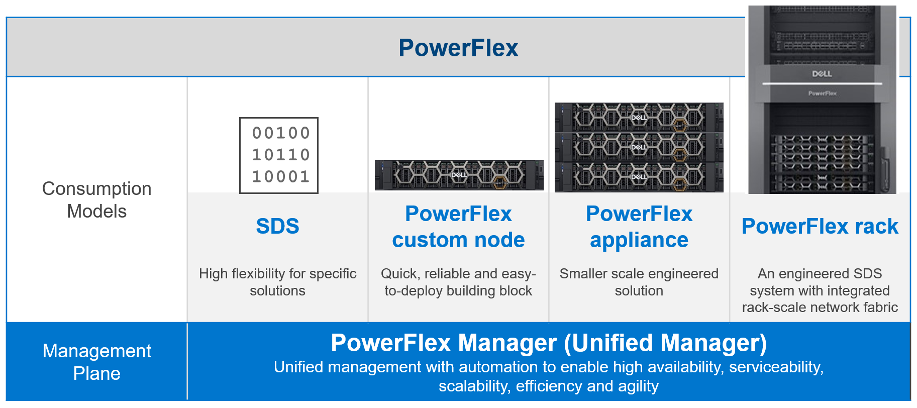
Figure 2. PowerFlex Management Plane 4.0
Single Authentication Method
The single endpoint allows the implementation of a single, and more secure, authentication method. The unified PowerFlex Manager uses the OAuth 2.0 industry standard for authorization. To authenticate, a user passes their username and password to PowerFlex Manager. The ingress microservice on PowerFlex Manager forwards the request to the authentication microservice.
Here’s an example of authentication with PowerFlex Manager v4.0:
curl --location --request POST 'https://<pfxm>/rest/auth/login' --header 'Content-Type: application/json' --data-raw '{"username": "admin", "password": "Password1234"}'
When a user session has been authenticated, they receive a bearer token in the response body. The bearer token can then be used with subsequent API calls as part of the authorization header.
Here’s an example of an authentication response, where access_token is the Bearer token used in subsequent API calls:
{ "scope": "openid profile email", "access_token": "eyJhb…_sHfNdkA9jTPgj_cOd-_lrlT_of2H7Nni9Yn-g", "expires_in": 300, "refresh_expires_in": 1800, "refresh_token": "eyJhb…J5uI_f1fkpB7vjatgc3Z3QQm1w8tFhSSkLVT4", "token_type": "Bearer", "id_token": "eyJhbGciO…ZoomRlk9ueJggFWCsC7BuNTKwhnCnNDRzzAUiw", "session_state": "d609babf-463d-4e49-84c3-e73360a90500" }
And here’s an example of passing the bearer token in a call to /rest/v1/alerts:
curl --location 'https://<pfmp>/rest/v1/alerts' --header 'Accept: application/json' --header 'Content-Type: application/json'--header 'Authorization: Bearer eyJhb…_sHfNdkA9jTPgj_cOd-_lrlT_of2H7Nni9Yn-g '
In earlier releases of PowerFlex, the REST API server on the PowerFlex Gateway used basic authentication, and the REST API server on the PowerFlex Manager used a custom authentication scheme. Having a single authentication scheme and endpoint simplifies the life of a PowerFlex administrator. The greater benefit, of course, is that OAuth 2.0 is a modern authorization protocol with the benefits of being an open standard.
Dell Technologies PowerAPI
Another enhancement is the adoption of the Dell Technologies PowerAPI style, which is compliant with the OpenAPI Specification (OAS) v3.0. This is the first phase of adopting the PowerAPI style and includes the features specified in the table below.
Feature | Description |
Authentication | Login, logout, & refresh token |
SSO | Manage users |
NAS | Manage PowerFlex file storage objects |
Alerts | Manage alerts and alert templates |
Events | Manage events |
Notifier | Manage external source and destinations, policies, and SMTP services |
Rest assured that the legacy REST API features from the PowerFlex Gateway and PowerFlex Manager remain unchanged in PowerFlex 4.0. The legacy APIs include PowerFlex Block API, PowerFlex Installation Manager API, and the PowerFlex Manager API. All will remain in place until they are fully integrated with the PowerAPI.
API | Description |
PowerFlex Block | Manage block storage, snapshots, and replication |
PowerFlex Manager | Compliance of rack and appliance |
PowerFlex Installer | PowerFlex Installation Manager/Gateway |
PowerAPI | Authentication, SSO, users, NAS, events, and alerts |
This is just a high-level introduction regarding improvements made in PowerFlex REST API 4.0. If you are looking for a deeper dive and some use case examples, check out my white paper listed in the resources section below. I have also included links to the Info Hub DevOps section and the PowerFlex REST API documentation on the Dell Technologies Developer portal.
To find out more about PowerFlex, contact your Dell representative.
Resources
Author: Roy Laverty, Principal Technical Marketing Engineer
Twitter: @RoyLaverty
Related Blog Posts
PowerFlex: CloudIQ Enhancements
Thu, 16 Nov 2023 22:07:06 -0000
|Read Time: 0 minutes
Have you checked out the All Features and Updates dialog in CloudIQ recently? If not, then let’s take a look together!
Figure 1. All Features and Updates dialog in CloudIQ
The first enhancement happened early this year with the addition of PowerFlex alerts. The alerts can be viewed through the System Alerts tile on the Home page, shown in figure 2, or by selecting Alerts under the Monitor menu. The System Alerts tile provides an alert count by severity level for all systems monitored by CloudIQ. Selecting the severity icon in the System Alerts tile redirects you to the Alerts page with a filter applied based on the selected severity.
Figure 2. System Alerts tile within CloudIQ Home page
Once on the Alerts page, you can apply additional filters. The Alerts page has a simple table layout and displays information such as severity, system name, and model alert description, as well as the date and time when the alert occurred. Details of an alert can be viewed by selecting the details icon, as highlighted in figure 3.
Figure 3. Details expanded for CloudIQ alert
In August, the PowerFlex/CloudIQ engineering team was busy releasing a bunch of exciting updates.
CloudIQ now supports Secure Connect Gateways (SCG) for PowerFlex systems. You can view the SCG information at a system level by visiting the PowerFlex system details page and clicking the GATEWAYS tab, highlighted in figure 3. The GATEWAYS tab consists of the gateway serial number, site information, location, gateway version, connectivity status, and heartbeat status.
Figure 4. GATEWAYS tab for Finance DC PowerFlex system
The SCG serial number links to the SCG details page shown in figure 5. All systems connected to the specific SCG are listed on the SCG details page. From here, you can launch the SCG UI by clicking the link at the upper right corner of the page, providing a seamless workflow when working with the gateway from CloudIQ.
Figure 5. SCG details page highlighting connected systems and the SCG UI launch
A Gateway column was added to the Admin>Connectivity page. The most recently active gateway for the PowerFlex system is listed in this column and contains a link to the gateway details page.
Figure 6. Gateway column on the Connectivity page
The next update is the Entitlements and System Licenses page, which you can find in the Admin section under Licenses. Here, you can check on the entitlements and licenses for all your PowerFlex systems. For more on this update, refer to the blog, Managing Dell PowerFlex Licensing and Being Way Less Sad.
Figure 7. Entitlements and System Licenses page
A new Entitlements tile is now available on the CloudIQ Home page, providing a summary of entitlement status. The Entitlements tile lets you quickly view the number of PowerFlex systems with entitlements and licenses that are expired, expiring withing 30 days, and expiring within 90 days.
Figure 8. Entitlement Expiration tile on CloudIQ Home page
Another location for entitlement and contract status is on the PowerFlex Systems tiles. An entitlement that is in good standing is marked with a green checkmark, soon to expire with a yellow icon, and expired with a red “x.”
Figure 9. Three entitlement and contract statuses in PowerFlex Systems tile
MDM cluster information was added to CloudIQ in July of this year. To view the MDM information, go to the system details page for the PowerFlex system and select the RESOURCES tab, shown in figure 10. You can view a list of the MDMs, MDM role, ID, management IP addresses, and software version.
Figure 10. PowerFlex system details page highlighting the RESOURCES tab under Inventory and the PowerFlex Manager launch
Another addition to the system details page is a link to PowerFlex Manager, making it convenient to launch the PowerFlex Manager UI for the specified system. A BLOCK tab provides details on PowerFlex components, including protection domains, fault sets, SDSs, devices, storage pools, volumes, and hosts. The views may feel familiar to you because they are based on the Block menu in PowerFlex Manager.
Figure 11. BLOCK tab within PowerFlex system details page
Planning on adopting APEX Block Storage for Public Cloud as part of your Multicloud strategy? CloudIQ has you covered on-prem and in the cloud.
Figure 12. CloudIQ Monitoring overview
Onboarding your APEX Block Storage for Public Cloud into CloudIQ brings visibility into the cloud infrastructure.
Figure 13. Inventory page for APEX Block Storage for AWS
The last enhancement that I will highlight is the addition of PowerFlex in custom reports. This update provides three report types, including anomaly charts, line charts, and table reports.
Figure 14. Three report types in a custom report for PowerFlex
The anomaly chart consists of a single performance metric overlaid on the gray historic seasonality value boundaries. The upper and lower bounds establish the normal behavior for the specific metric. The bounds are based on an analysis of the prior three-week history. Historical values that exceed the upper or lower bounds are shaded in light blue to highlight that the value of the metric during this time was outside the historical range. Anomaly charts, at most, display the last 24 hours of data. The line chart allows you to display more than one metric from one or more systems. The example in figure 14 shows system latency from three PowerFlex systems. The table displays metrics and properties, such as system name and code version.
The next time you are working with CloudIQ, keep an eye out for the latest enhancements. If you have not onboarded your PowerFlex systems into CloudIQ, check out the PowerFlex CloudIQ onboarding article to get started.
Resources
Procedure to Onboard PowerFlex Systems to CloudIQ
Author: Roy Laverty, Principal Technical Marketing Engineer
Twitter: @RoyLaverty
LinkedIn: https://linkedin.com/in/roy-laverty
PowerFlex: The DNA of the Ultimate Software-Defined Infrastructure
Mon, 25 Sep 2023 13:24:55 -0000
|Read Time: 0 minutes
Introduction
This blog is the first in a series discussing PowerFlex software-defined infrastructure.
PowerFlex is Dell Technologies’ flexible, resilient, and highly scalable software-defined infrastructure, providing both block and file storage services. Its software-first DNA can be traced back to influential Dell software-defined products such as ScaleIO and VxFlex.
PowerFlex software runs on the ubiquitous x86 node with TCP/IP networking, leveraging the market-leading PowerEdge server in configurations that have been tested and qualified to run PowerFlex.
Flexible consumption options
PowerFlex comes in four consumption options: PowerFlex rack, PowerFlex appliance, PowerFlex custom node, and APEX Block Storage for Public Cloud.
- PowerFlex rack is a fully engineered rack-scale system with integrated networking, management nodes, and intelligent cabinet. A turn-key solution with increased time-to-value, the value of PowerFlex rack is hard to beat.
- PowerFlex appliance provides the same level of performance as PowerFlex rack but at a smaller starting point and with greater networking options to fit a wide variety of requirements.
- PowerFlex custom node is a DIY experience compared to PowerFlex rack or PowerFlex appliance, yielding the greatest configuration flexibility of all. Custom node deployments—as the name implies—are a node level offering and do not include integrated networking.
- APEX Block Storage for Public Cloud is a deployment of the Dell software-defined block storage in the public cloud. It provides higher performance and resiliency beyond what is available with native public cloud providers.
Figure 1. PowerFlex consumption options
Flexible architecture
There are three building blocks that give PowerFlex its power.
The first is the storage cluster manager called the Meta Data Manager (MDM), which sits outside of the data path. The MDM is a highly available, tightly coupled software cluster of three or five nodes, which has a supervisory role monitoring system health, managing the configuration, and coordinating the rebuilding and protection of data.
The second software component is the storage creator also known as the Storage Data Server (SDS). The SDS abstracts the local storage in each node into one or more storage pools and presents the volumes that have been provisioned from its local storage to the storage consumer.
The third component is the storage consumer called the Storage Data Client (SDC). The SDC is installed on the application node and presents the PowerFlex volume as a block device to the operating system.
Figure 2. PowerFlex building blocks
These pieces of software can be installed on the nodes in almost any combination. How they are installed defines the role of the node in a PowerFlex system as well as the type of deployment. The following figure shows a two-layer system with a set of four storage nodes (SDS) and two compute nodes (SDC).
Figure 3. Two-Layer configuration
An advantage of the two-layer deployment is that we can scale the storage and compute independently. Additionally, it reduces license costs on application and compute environments that license by CPU core count. The SDC and SDS can also be installed on the same node to create an HCI deployment as shown in Figure 4, reducing complexity and resulting in increased operational efficiencies.
Figure 4. HCI configuration
We can also mix two-layer and HCI, all in a single PowerFlex system, as shown in Figure 5.
Figure 5. Mixed – Two-Layer and HCI
As you can see from the available consumption and deployment options, PowerFlex provides extreme flexibility, but it does not end there. PowerFlex boasts broad support for compute operating environments and applications, including Windows and many Linux distributions, and multiple hypervisor environments. PowerFlex is also a fantastic platform for containerized cloud native applications.
Flexibility evolved
PowerFlex is a continually evolving solution. The most recent steps in the evolution are file services, as illustrated in Figure 6, and NVMe/TCP support for front-end (application) connectivity.
PowerFlex file services use physical nodes for NAS controllers and are similar to compute nodes. When the file service is deployed, an NAS container and an SDC are installed on each dedicated file node. A single NAS cluster is supported per PowerFlex system (MDM cluster). The NAS cluster supports anything from two to sixteen physical NAS controller nodes.
The backend block storage supporting the NAS file system is PowerFlex block storage provisioned from a storage pool. Volumes are created within the selected storage pool for NAS meta data and for user file systems. PowerFlex file storage supports NFSv3/v4, SMBv2/v3, and FTP and SFTP.
Figure 6. File services
The NVMe specification was established in 2013 to address the issue of using fast, direct, attached nonvolatile storage media with slower interfaces such as SAS. In 2016, the standard was extended to include NVMe devices used over fabrics (NVMe-oF). The SDC is not compatible with the NVMe/TCP protocol, however most operating system vendors have started to adopt NVMe/TCP natively. As such, a change in host connectivity was required to support NVMe/TCP connectivity, as illustrated in Figure 7.
I mentioned earlier that the SDC holds a map of the volume layout on the storage nodes. The map of the volume layout must be known so that reads and writes go to the appropriate SDS and device. Without an SDC, the mapping logic had to be moved from the compute node to the PowerFlex storage system. Likewise, the translation of the NVMe protocol used by the host to the proprietary PowerFlex protocol on the backend is another technical gap that needed to be filled.
Enter a new PowerFlex software module called the Storage Data Target (SDT). The SDT is installed on the storage nodes alongside the SDS and is responsible for translating the compute IO using NVMe protocol to the PowerFlex protocol. The map of the volume layout held by the SDC has been moved to the SDT.
Figure 7. NVMe/TCP host connectivity
NOTE: Dell PowerFlex and most Linux distributions support NVMe/TCP in tech preview only. Consult with your operating system vendor documentation and the latest PowerFlex documentation for updated information regarding NVMe/TCP support. NVMe/TCP connectivity between VMware ESXi and Dell PowerFlex is supported.
Unmatched scalability
PowerFlex has high growth potential and can scale to thousands of nodes. You can start as small as a four-node system and add nodes as business needs dictate. Furthermore, adding nodes is a nondisruptive operation. More detailed specifications can be found in the PowerFlex Specification sheet.
Software-defined infrastructure
The SDS on each storage node abstracts the local disks and federates all of them into storage pools. In addition to aggregating the storage capacity, PowerFlex software also aggregates the performance capability of each node. For example, if one node has 20 TB of storage and can perform 100k IOPs, then two nodes provide 40 TB of storage and 200k IOPs.
Figure 8. Software-defined infrastructure
Internal testing at Dell has shown a near linear improvement in performance when adding nodes, as displayed in Figure 9, providing predictable gains when adding nodes to a PowerFlex system.
Figure 9. Linear improvement with IOPs
The same linear improvement observed with IOPs in PowerFlex is seen with throughput in Figure 10, all while maintaining submillisecond response times.
Figure 10. Linear improvement with throughput
Perfect balance
The MDM determines how to lay out the volume address space in the storage pool when it is created, as illustrated in Figure 11. The MDM sends the data map to the SDSs that are contributing storage and to the SDC that is consuming the volume. Notably, the MDM distributes the volume address space evenly across every SDS and every hard drive that is contributing storage to the storage pool.
Figure 11. Volume addressing
The MDM continually monitors resources and ensures that there are no hot spots in the system. The SDSs communicate with each other over the backend mesh when an imbalance is detected and begin the process of rebalancing. This balancing act ensures capacity is evenly distributed across the backend devices and performance is distributed across the backend mesh, the result of which is displayed in Figure 12. Note that the rebalance is a background process and does not impact production IO.
Figure 12. Balanced devices
PowerFlex also ensures that reads and writes to the volume are balanced across the SDSs in the storage pool.
Figure 13. Balanced SDSs
An SDC will use every SDS over a client/server mesh, illustrated in Figure 14. The SDC has automatic multipathing to each of the SDSs, ensuring IOPs are balanced over the front end. This massively parallel architecture ensures maximum throughput while minimizing latency.
Figure 14. Client-Server mesh
Intelligent resiliency
The mesh technology in PowerFlex that gives it incredible performance is also the foundation of its outstanding resiliency. If a drive or node fails, the SDSs will use the same mechanism described in the previous section to rebalance and rebuild data, ensuring 6 9’s of availability[1]. PowerFlex can reprotect the data in seconds after a drive failure and in minutes after a node failure. The following figure elucidates how the rebuild duration improves with scale.
Figure 15. Rebuild duration
PowerFlex does not use any type of hardware disk-level RAID protection. Instead, on write operations, the SDC sends a chunk of data to an SDS (primary). The SDS then writes the data to a hard drive on the local node. The SDS also ships the chunk to a second SDS (secondary) node which then writes the data to a disk on that node.
Figure 16. Data mirroring
What about planned outages for maintenance? PowerFlex gives administrators three maintenance mode options, each of which is nondisruptive.
The first is Node removal, which is a graceful removal of a single node. PowerFlex does a many-to-many rebalance of data among the remaining nodes during a node removal operation. Data is fully protected, and the PowerFlex system remains operational. The system capacity and performance potential will be reduced when the operation is initiated. This mode is typically used to permanently remove a node from the cluster.
Instant Maintenance Mode (IMM) is designed for quick entry and exit from the maintenance operation. IMM is ideal for rolling upgrades where the maintenance window is short. Data on the node is unavailable and not rebalanced to other nodes in the cluster when a node is placed in IMM. Applications accessing data during IMM are directed to other nodes containing the copy of data. Writes are tracked, and when the node exits IMM, the changes are written to the node in question.
The last mode is called Protected Maintenance Mode (PMM), which provides similar data availability to the other maintenance modes without the single copy exposure risk of IMM. As with the node removal operation, when a node is placed into PMM, PowerFlex will perform a many-to-many copy rebalance to the other nodes. Data on the node placed in PMM is unavailable upon entering and during PMM. Work cannot begin on the node until the copy is complete. Entering PMM takes longer to ensure the data on the node is copied to other storage nodes.
Like IMM writes affecting the node are tracked, and once the node exits PMM, the updates are written to the node. For more detailed information about PowerFlex maintenance modes, check out this white paper.
Management and orchestration
PowerFlex offers an extensive management and orchestration (M&O) ecosystem, starting with PowerFlex Manager. PowerFlex Manager is the unified management application for all PowerFlex consumption models, providing life cycle management, automation, and compliance of software and firmware for PowerFlex rack and appliance. PowerFlex Manager also automates life cycle management of core PowerFlex software for all consumption models.
Figure 17. PowerFlex Manager LCM
In addition to life cycle management, PowerFlex Manager reports on the health, capacity, and performance of PowerFlex hardware components and software and is the ingress point for the full-featured PowerFlex REST API.
Dell Technologies offers automation tools for PowerFlex such as a Python SDK, Ansible modules, and a Terraform provider. Looking to place containerized workloads on PowerFlex? Dell Technologies provides a Container Storage Interface (CSI) driver and Container Storage Modules (CSM) for managing a Kubernetes infrastructure on PowerFlex. Want more information about this topic? Head over to GitHub.
Conclusion
I could continue about the PowerFlex DNA, but I think we can wrap up for now. Stay tuned for more to follow in a future blog. If you are looking for more information in the meantime, head over to Dell Technologies Info Hub where you will find great technical resources such as white papers, reference architectures, solution briefs, and videos.
Resources
Dell PowerFlex YouTube Channel
From Chaos to Order Unifying Silos infographic
Dell Technologies GitHub Repository
Dell PowerFlex: Maintenance Modes
Author: Roy Laverty, Principal Technical Marketing Engineer
LinkedIn: https://linkedin.com/in/roy-laverty
Twitter: @RoyLaverty
[1] Availability claims based on internal Dell testing. (Source: Dell PowerFlex - Unbounded software-defined infrastructure platform.)