This section demonstrates the creation of NVMe/TCP storage networks in the PowerStore cluster.
Note: This example uses NVMeTCP-SAN-A and NVMeTCP-SAN-B.
From the Dell PowerStore UI, click the Settings icon.
Figure 81. Settings Menu in PowerStore UI
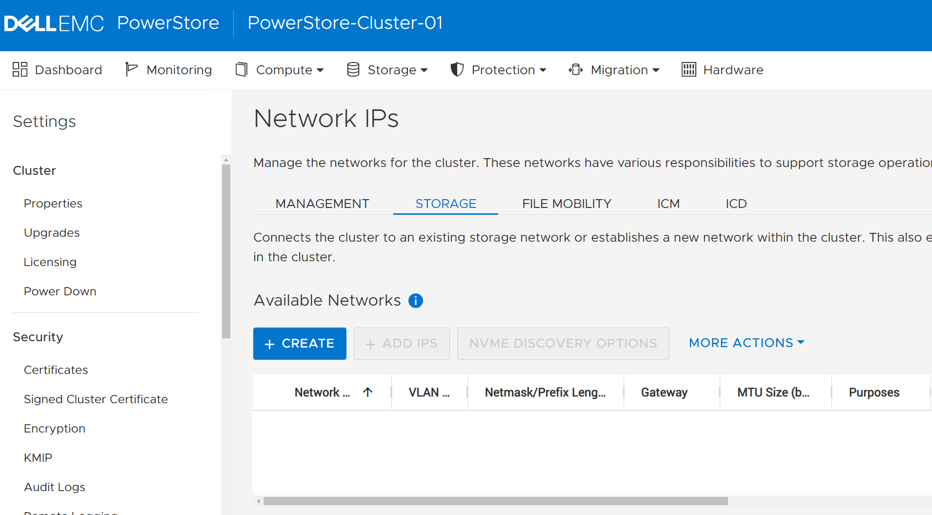
Under the Networking section, select Network IPs > STORAGE.
Figure 82. Storage Networks tab in PowerStoreOS 2.1.x Figure 83. Storage Networks tab in PowerStoreOS 3.x
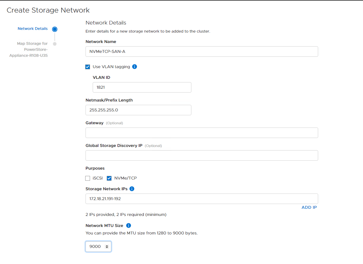
Click CREATE. In this example, the following options are selected:
Network Name:NVMeTCP-SAN-A
Click to select the Use VLAN tagging box
VLAN ID: 1821
Netmask/Prefix Length:255.255.255.0
Note: If leveraging Layer 3 routing for NVMe/TCP, enter a Gateway. For example, 172.18.21.254.
Do not enter a Global Storage Discovery IP.
From the Purposes option, click to clear the check from the iSCSI option. Note: Verify that NVMe/TCP is the only Purpose that is selected.
For Storage Network IPs, enter 172.18.21.191 and 172.18.21.192
Set the Network MTU Size to match the end-to-end network. This example uses 9000.
Figure 84. Create Storage Network for SAN A
Click NEXT.
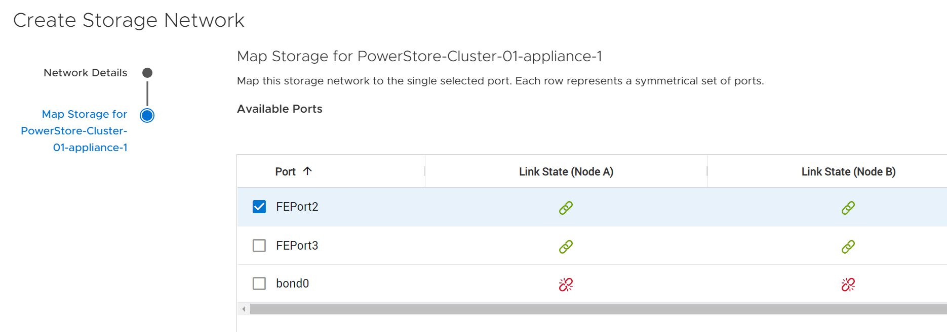
Map the new SAN A storage network to physical ports. This example uses FEPort2. PowerStore will automatically map the new network to port 2 on both nodes.
Figure 85. Map PowerStore port to SAN A
Note: For air-gapped SAN switches, do not use FEPort0 and FEPort1 as they are in a bond. See the PowerStore Networking Guides page for more information.
Click FINISH.
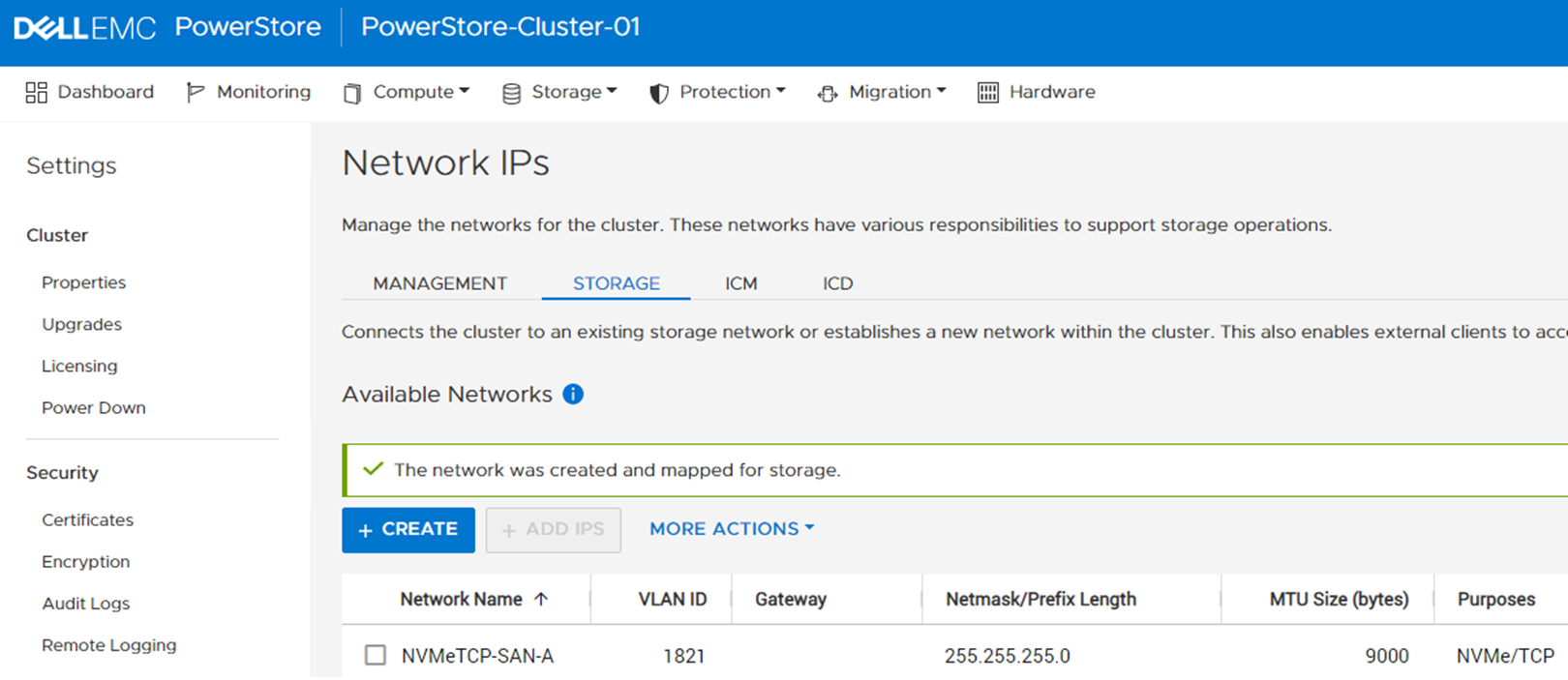
Figure 86. Storage mapping completed successfully
Click Finish again.
Figure 87. New SAN-A Storage Network added
Repeat the steps above to add the second, NVMeTCP-SAN-B network, using the following criteria:
Network Name: NVMeTCP-SAN-B
VLAN ID: 1822
Netmask/Prefix Length: 255.255.255.0
Note: If leveraging Layer 3 for NVMe/TCP, enter a Gateway IP address. For example, 172.18.22.254.
Do not enter a Global Storage Discovery IP.
From the Purposes option, click to clear the check from the iSCSI option. Verify that NVMe-TCP is the only Purpose that is selected.
Storage Network IPs: 172.18.22.191-192
Set the Network MTU Size to match the end-to-end network. This example uses 9000.
Click Next.
Figure 88. Create Storage Network for SAN B
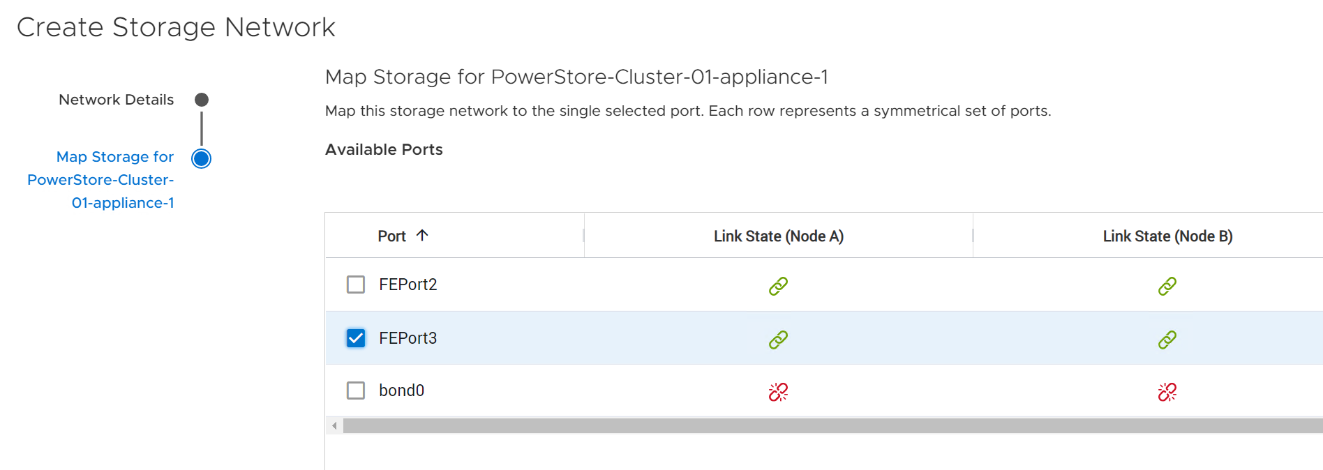
Map the new SAN B storage network to physical ports. This example uses FEPort3. PowerStore will automatically map the new network to port 3 on both nodes.
Figure 89. Map PowerStore port to SAN B
Click FINISH.
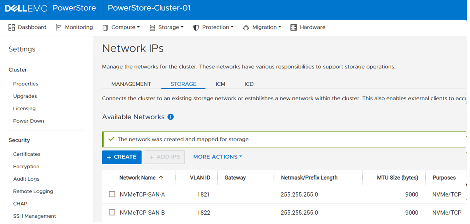
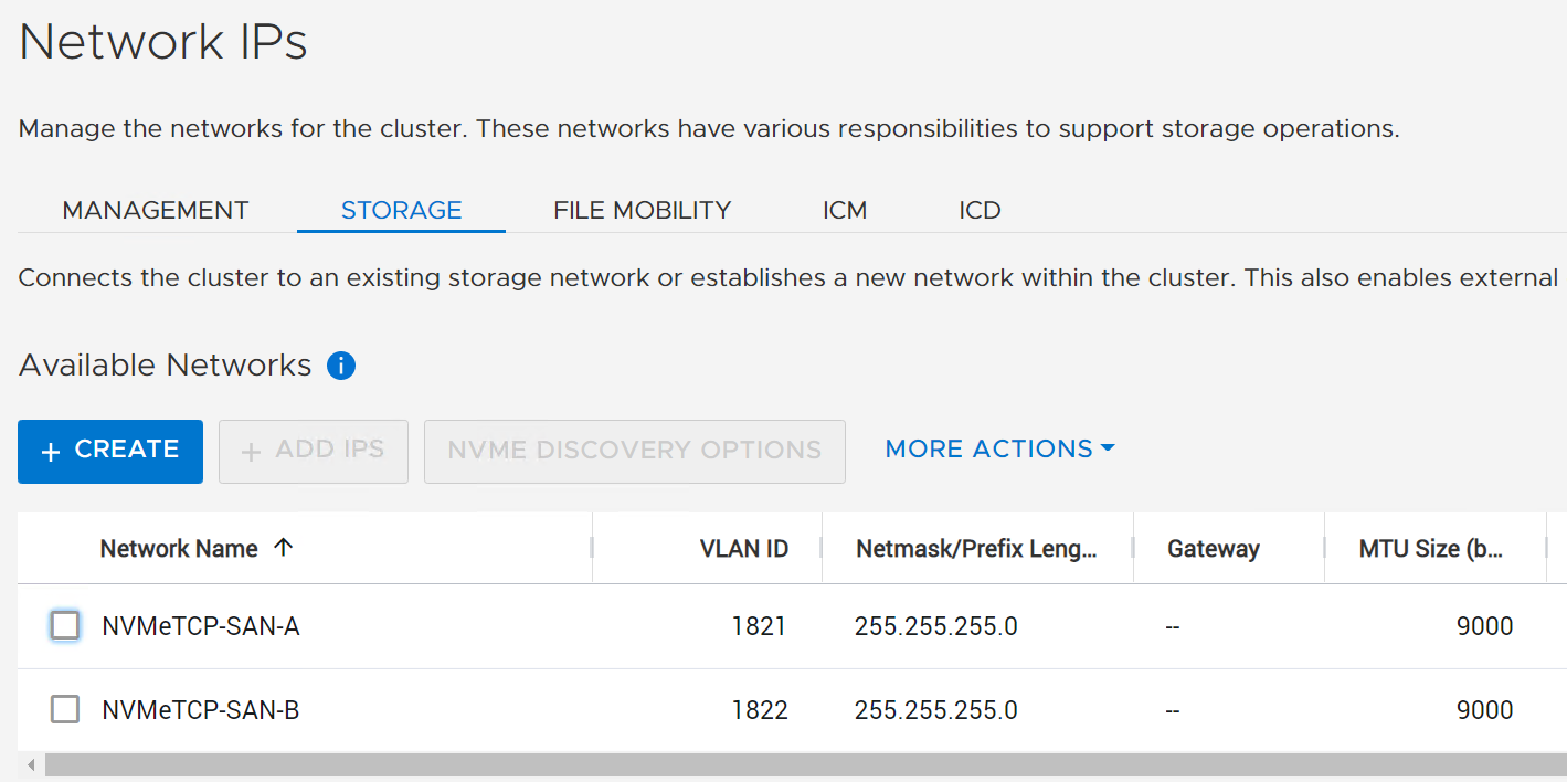
Figure 90. New SAN-B Storage Network added in PowerStoreOS 2.1.x Figure 91. New SAN-B Storage Network added in PowerStoreOS 3.x
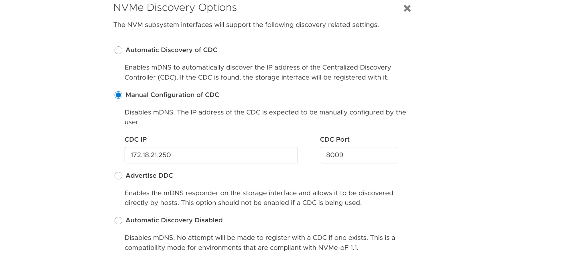
If PowerStore and CDC are on different subnets, the CDC IP must be set in PowerStore Manager or SFSS.
For PowerStoreOS 2.1.x, the DDCs are configured in SFSS. See the Manually add a DDC in SFSSsection after the SFSS has been deployed and CDCs are enabled.
If PowerStoreOS 3.x is installed and the CDC is on a different subnet to the storage network, click NVME DISCOVERY OPTIONS. Figure 92. Click NVMe Discovery Options Then change the selection from the default Automatic Discovery of CDC to Manual Configuration of CDC and enter the CDC IP address and port.


 Note: For air-gapped SAN switches, do not use FEPort0 and FEPort1 as they are in a bond. See the PowerStore Networking Guides page for more information.