Create port groups for SFSS VM NVMe/TCP control traffic
This example uses distributed port groups, but standard port groups can also be used.
Log in to the vSphere web client.
Click the Networking option.
Select the vDS used for the SFSS VM’s NVMe/TCP Control traffic. This example uses the C01-vDS-Management vDS.
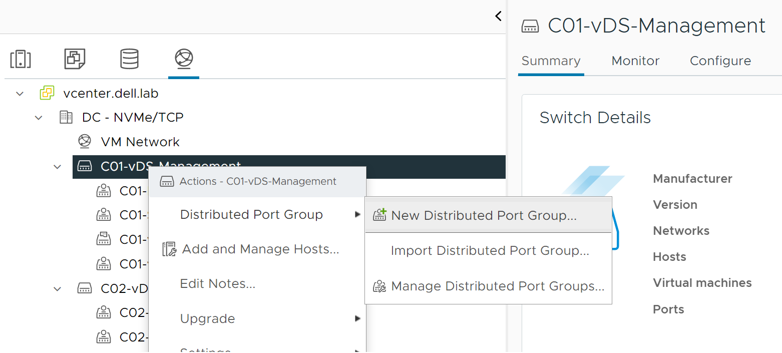
Right-click the vDS listing and select Distributed Port Group.
Click New Distributed Port Group.
Figure 111. Add New Distributed Port Group
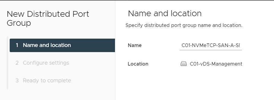
Provide a name for the first port group. This example uses the C01-NVMeTCP-SAN-A-SFSS port group.
Figure 112. Provide a Name for the port group
Click NEXT.
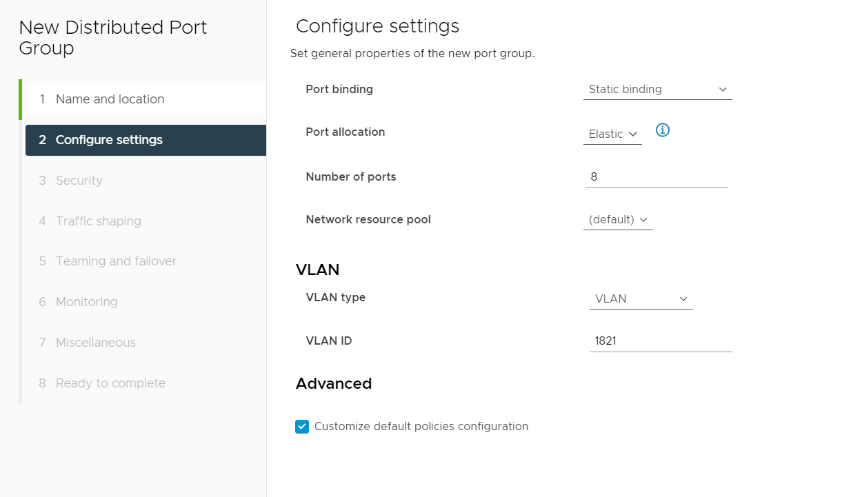
On the Configure Settings page, select VLAN from the VLAN type field.
Enter the VLAN ID in the field provided. This example uses VLAN ID 1821.
From the Configure settings screen, click to select the box next to Customize default policies configuration, and then click NEXT.
Figure 113. Distributed Port Group Settings
From the Security page, click NEXT to accept the default options.
On the Traffic shaping page, click NEXT to accept the Disabled default options.
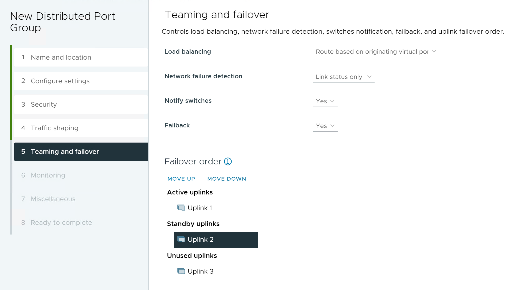
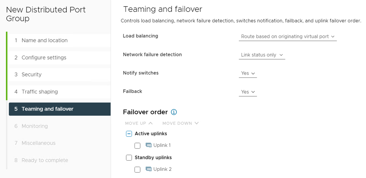
From the Teaming and failover page, select and move the uplinks individually so that there is one Active uplink, and one Standby uplink, as shown in the figure below.
Note: Port groups created for the SFSS VM can leverage teaming with Active/Standby or Active/Active uplinks. In this example, the teaming is configured for Active/Standby, Uplink 1 is active and Uplink 2 is the standby should there be a failover scenario. Uplink 3 is not used in this example.
Figure 114. Teaming and failover page for C01-NVMeTCP-SAN-A-SFSS port group
Click NEXT.
Click NEXT to accept the NetFlow – Disabled default setting on the Monitoring screen.
Click NEXT to accept the Block All Ports – No default setting on the Miscellaneous screen.
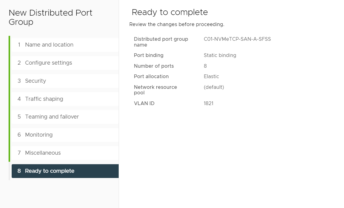
Review the Ready to complete screen, and then click FINISH.
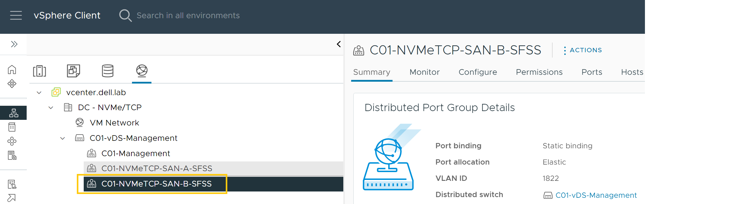
Figure 115. Ready to complete confirmation screen The new Distributed Port Group is configured and displays under the C01-vDS-Management vDS. Figure 116. New Distributed Port Group created - SAN B
To create the SFSS VM SAN B Control Traffic distributed port group, perform the following steps:
Select the vDS. In this example, C01-vDS-Management is selected.
Right-click and select Distributed Port Group.
Click New Distributed Port Group.
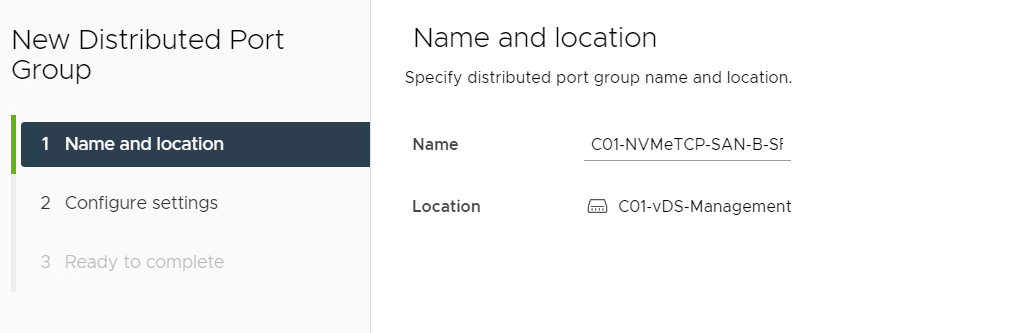
Provide a name for the second port group. In this example, C01-NVMeTCP-SAN-B-SFSS is used.
Figure 117. Provide a Name for the Port Group
Click NEXT.
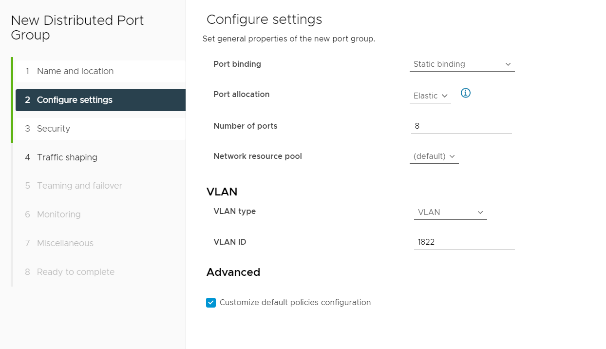
On the Configure Settings page, select VLAN from the VLAN type field.
Enter 1822 as the VLAN ID for this example.
Check the box next to Customize default policies configuration.
Figure 118. Distributed Port Group settings
Click NEXT.
On the Security page, leave the options at their default settings, and then click NEXT.
From the Traffic shaping page, leave the default Disabled settings, and then click NEXT.
On the Teaming and failover page, select and move the uplinks individually so that there is one Active uplink, and one Standby uplink, as MLAG is not used on the connected switch ports in this example.
Figure 119. Teaming and failover page
On the Monitoring screen, leave the Netflow option at its default Disabled setting, and then click NEXT.
From the Miscellaneous screen, leave the Block All Ports option at its default No setting, and then click NEXT.
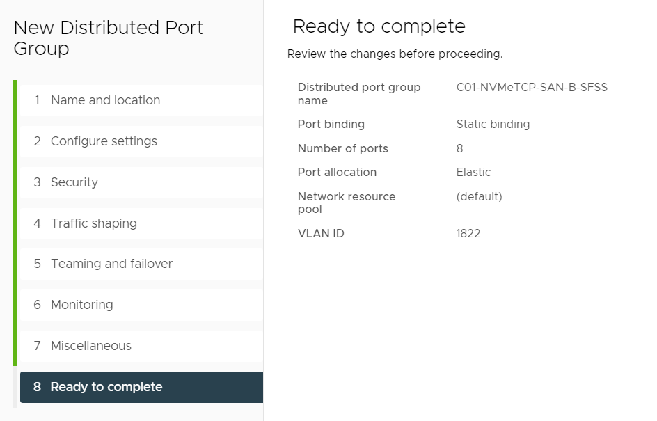
Review the Ready to complete screen, and click FINISH.
Figure 120. Ready to complete confirmation screen
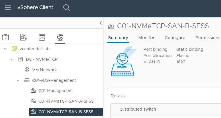
The second Distributed Port Group is configured and displays under the C01-vDS-Management vDS.
Figure 121. Configuration confirmation of Distributed Port Groups