PowerFlex two-layer configuration with an MX7000 logical network
Home > Storage > PowerFlex > Guides > Deployment Guide—Dell EMC PowerFlex with Dell EMC PowerEdge MX7000 Chassis > PowerFlex two-layer configuration with an MX7000 logical network
PowerFlex two-layer configuration with an MX7000 logical network
-
The following figure shows the logical network on a PowerFlex two-layer configuration with an MX7000 solution with four data networks:
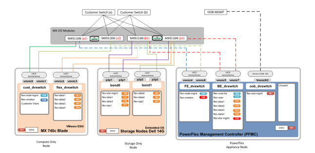
Figure 2. Logical network for a PowerFlex two-layer deployment with an MX7000 chassis
Note:
There were two VLAN design changes on the PowerFlex Management Controller from our standard logical design, which are shown in red:- FE_dvswitch—Removed flex-stor-mgmt and added flex-vmotion
- BE_dvswitch—Removed flex-vmotion added flex-stor-mgmt
The management/production MX91B16n switches provide network connectivity to the customer environment and are connected, as shown in the following figure:
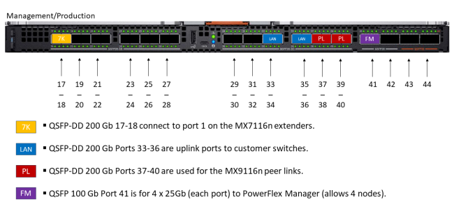
Figure 3. MX9116n FSE management/production network connectivity
The MX9116n FSE modules that are located inside the B chassis slots provide storage connectivity to the PowerFlex storage-only nodes, as shown in the following figure:
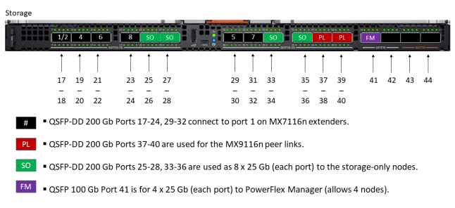
Figure 4. MX9116n FSE modules in B chassis slots
The MX7116n FEM modules are used to connect multiple chassis. The following figure shows the MX7116n FEM module and its associated connectivity ports:

Figure 5. MX7116n FEM and associated connectivity ports
To provide a better representation of a fully cabled system, the following figure shows the MX9116n FSE and MX7116n FEM connections:
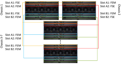
Figure 6. MX9116n FSE and MX7116n FEM connections
MX740c compute nodes architecture
Each node in the MX740c compute architecture is inserted into an MX7000 chassis and contains two network mezzanine adapters. Each mezzanine adapter contains two 25 GbE network links for a total of four 25 GbE links per node. The following figure shows that the mezzanine adapters are hard wired to a specific fabric slot.
Note: This detail was considered when we configured the MX7000 chassis and associated nodes for maximum high availability.
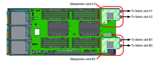
Figure 7. MX740c compute architecture
Because each chassis contains a pair of MX9116n FSE modules and a pair of MX7116n FEM modules, the internal connections alternate when Chassis1 Node1 is compared with Chassis2 Node1 for high availability and redundancy purposes. Each mezzanine card is connected to one MX9116n FSE and one MX7116n FEM.
For example:
- Chassis 1 Node 1 connects to switch port 1/1/1 on B1 and A2, and switch port 1/71/1 on B2 and A1.
- Chassis 2 Node 1 connects to switch port 1/71/1 on B1 and A2, and switch port 1/1/1 on B2 and A1.
