The following table shows the values entered in the OMNI plug-in in vCenter for this example. The following steps are run once for each uplink using the values from the table.
| Link label | E | F | G | H |
| Uplink Port Type | L3 | L3 | L3 | L3 |
| L3 Type | L3 Routed Interface | L3 Routed Interface | L3 Routed Interface | L3 Routed Interface |
| Name | Spine01-to-ExternalA | Spine02-to-ExternalA | Spine01-to-ExternalB | Spine02-to-ExternalB |
| Switch Group | Spine | Spine | Spine | Spine |
| Node | Z9264-SPN1 | Z9264-SPN2 | Z9264-SPN1 | Z9264-SPN2 |
| Interface | Ethernet 1/1/27 | Ethernet 1/1/27 | Ethernet 1/1/28 | Ethernet 1/1/28 |
| Network Name | SPN01-to-ExtA | SPN02-to-ExtA | SPN01-to-ExtB | SPN02-to-ExtB |
| Prefix Length | 31 | 31 | 31 | 31 |
| IP Address | 192.168.1.5 | 192.168.1.7 | 192.168.2.5 | 192.168.2.7 |
| Routing Protocol | eBGP | eBGP | eBGP | eBGP |
| Policy Name | eBGP-SPN01-to-ExtA | eBGP-SPN02-to-ExtA | eBGP-SPN01-to-ExtB | eBGP-SPN02-to-ExtB |
| Peer Interface IP address | 192.168.1.4 | 192.168.1.6 | 192.168.2.4 | 192.168.2.6 |
| Peer ASN | 65101 | 65101 | 65101 | 65101 |
| PFD Neighbor | Disable | Disable | Disable | Disable |
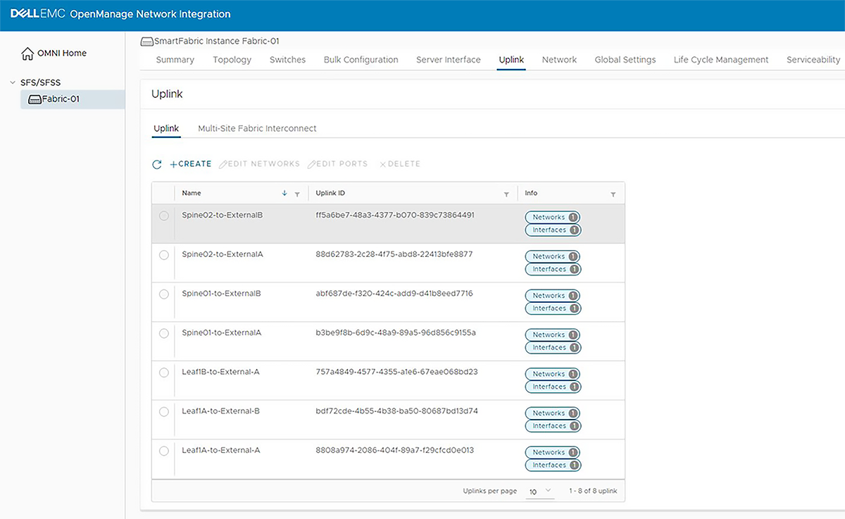
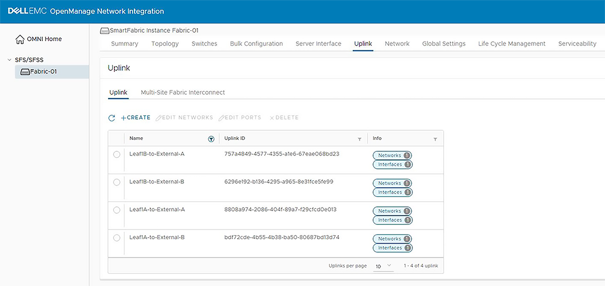
In the OMNI plug-in in vCenter, select the Service Instance in the left pane. In the right pane, click the Uplink tab. The existing uplinks from the leaf switches are displayed, as shown.
To create uplinks from the spine switches, perform the following steps.
- On the Uplink Details page:
- Set the Uplink Port Type to L3.
- Set the L3 Type to L3 Routed Interface.
- Enter a unique Name and, optionally, a Description.
Figure 221. Uplink Details page 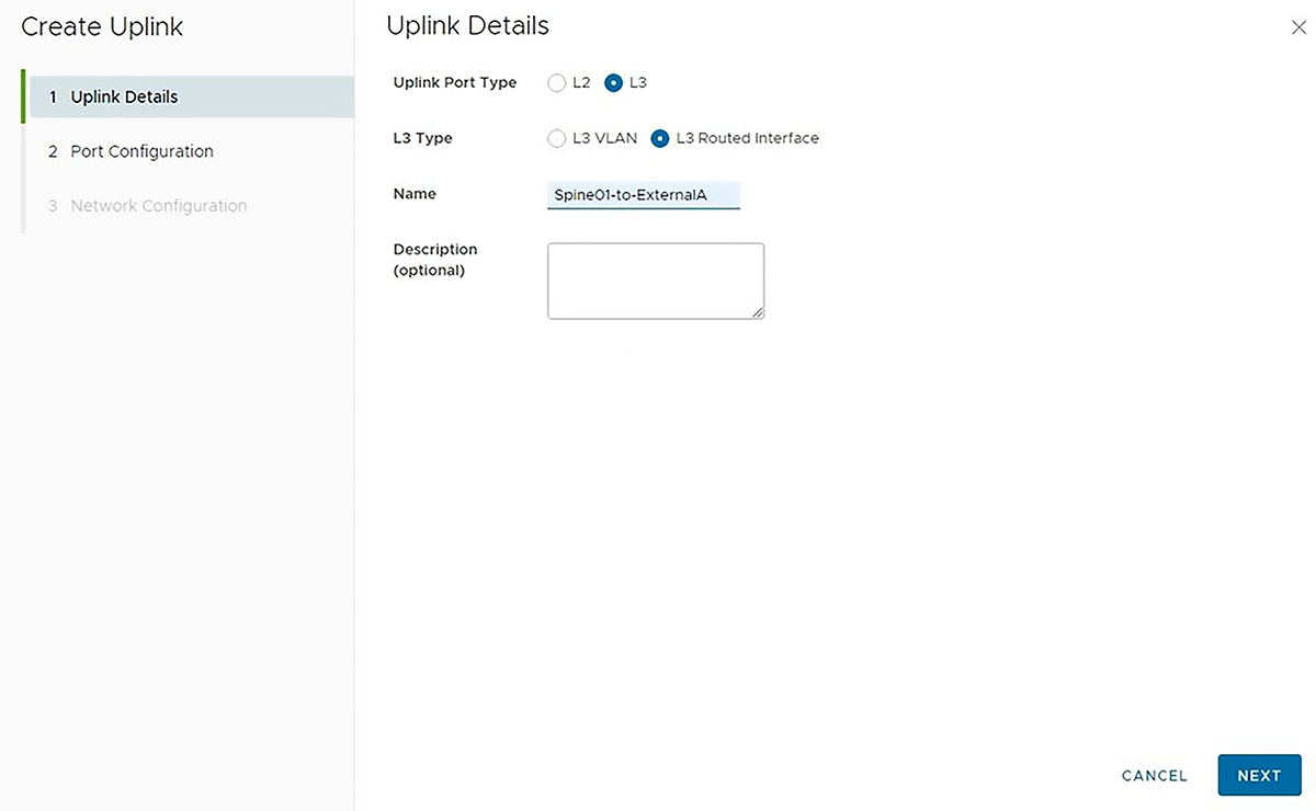
- On the Port Configuration page:
- Set the Switch Group to Spine.
- The Domain is set to the Fabric ID by default.
- Select the Node, Z9264F-Spine1 in this example.
- Select the appropriate interface, ethernet 1/1/27 in this example.
Figure 222. Port Configuration page 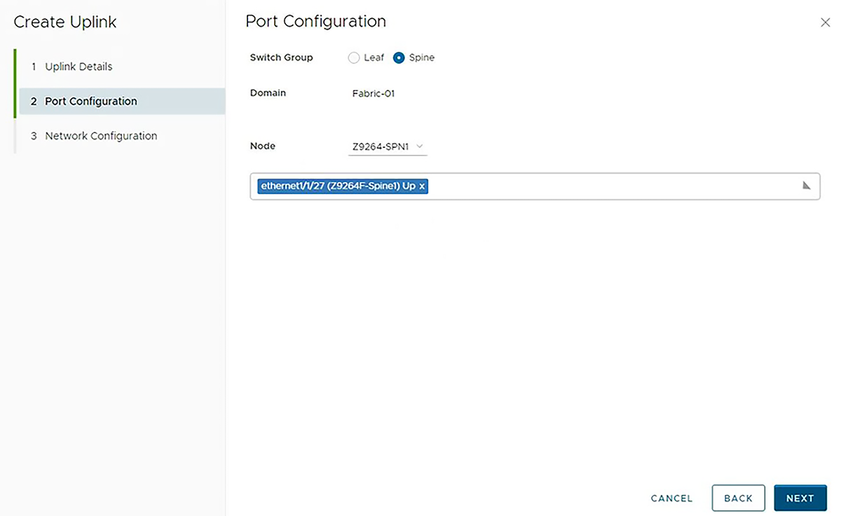
- On the Network Configuration page:
- Set the Prefix Length to 31, and set the IP Address, 192.168.1.5 in this example.
Figure 223. Network Configuration page 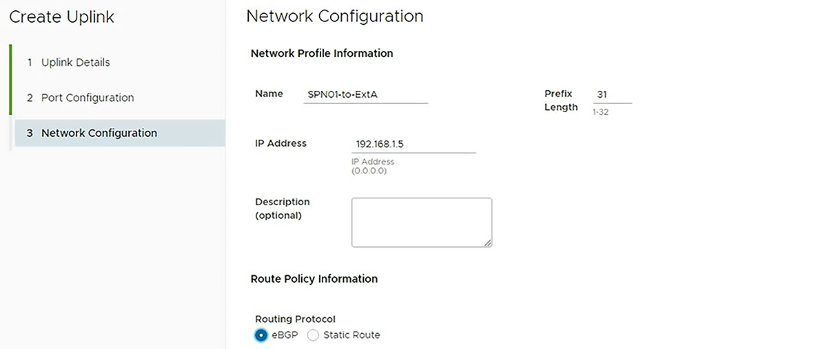
- BFD is left at the default, disabled.
Figure 224. Network Configuration page continued 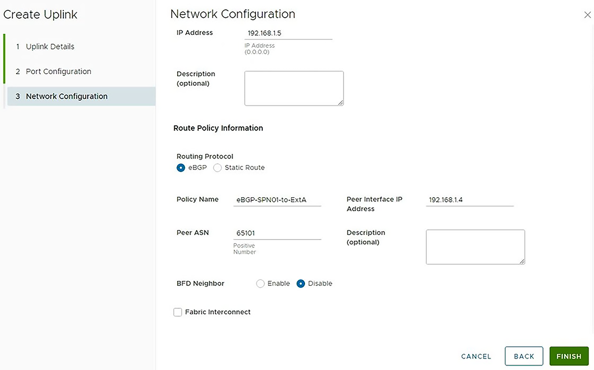
- Set the Prefix Length to 31, and set the IP Address, 192.168.1.5 in this example.