
Before following the procedure to onboard PowerStore T nodes, ensure that the following tasks have been completed:
- The networking fabric is built out using SFS. The switches in the multirack topology are in SmartFabric mode.
- The fabric connects to the external switches using L2 uplinks. The appropriate configuration has been completed on the external switches.
- ESXi nodes 1 and 2 are onboarded to the fabric.
- vCenter and OMNI are deployed on ESXi node 1.
- The ESXi nodes are added to a cluster in vCenter, as shown in the following figure:
Figure 158. ESXi nodes added to the cluster 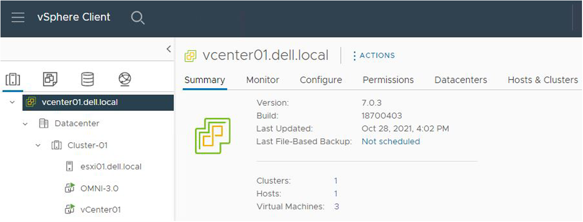
- The associated networks are created. VLAN 1820 is used for PowerStore storage traffic.
The following table lists the networks for PowerStore T deployment. See
Configure General Purpose Networks Using OMNI for more information.
Table 20. Networks for PowerStore T deployment Networks for PowerStore T Network Tagged/Untagged Optional/Required Management 1811 Tagged Required Storage 1820 Tagged Required NFS 1821 Untagged Optional Discovery 1819 Untagged Optional Note: There is an internal, untagged network used for discovery and future features such as clustering. Dell Technologies recommends that you set up the untagged network for future use.Note: Only one untagged network may be selected. If the Discovery and NFS networks are required, the NFS network must be a tagged network.
PowerStore T requires management and storage networks.
- Ports 1/1/15 and 1/1/16 on Leaf2A and Leaf2B are broken out to 10 GbE. See the breakout example in Breakout Interface.
S5248F-Leaf2A# show interface status | grep up Port Description Status Speed Duplex Mode Vlan Tagged-Vlans Eth 1/1/15:1 up 10G full A - Eth 1/1/16:1 up 10G full A - ***** OUTPUT TRUNCATED ***** - The vDS configuration in vCenter has the following port groups:
Table 21. vDS port groups VLAN ID Description 1811 Management 1812 vMotion 1814 VM Network A 1815 VM Network B 1820 Storage - OOB management Note: If the NFS and the Discovery networks are both required, an additional vDS port-group for NFS with the VLAN ID of 1821 is required.
The vDS configuration topology view is shown in the following figure:
Figure 159. vDS topology view 