
To deploy the PowerStore T appliance, perform the following steps. The Management Network that is specified in the initial deployment of the PowerStore T uses the 1GbE management connection on back of the PowerStore appliance. The 10GbE connections to the Fabric are configured after initial deployment for the Storage network.
The table below lists out all the values that were used for the PowerStore T deployment.
| Parameter | Value |
| Cluster Name | Cluster-01 |
| Drive Failure Tolerance | Single Drive Failure |
| Management VLAN ID | |
| Management Netmask/Prefix Length | 24 |
| Management Gateway | 100.67.108.254 |
| Management Cluster IP | 100.67.108.100 |
| Management Network IPs | 100.67.108.101-103 |
| DNS Server | 100.67.10.1 |
| NTP Server | 100.67.10.20 |
| SupportAssist | Skip |
| Storage VLAN ID | 1820 |
| Storage Netmask/Prefix Length | 24 |
| Storage Gateway | 172.18.20.254 |
| Storage Network Ips | 172.18.20.200-206 |
- Log in by using the default credentials - admin/Password123#.
Figure 168. PowerStore Manager login screen 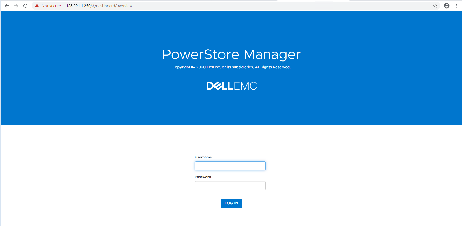
- Provide a name for the cluster in the Cluster Name field, and then click NEXT.
Figure 169. Cluster Details screen 
- Change the admin user's Factory Default Password.
Figure 170. Change the admin password 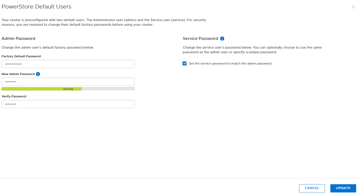
- Using the Parameter and Value information in the table above, enter the Management network details, and then click Next.
Figure 171. Management Network details screen 
- Using the Parameter and Value information in the table above, enter the DNS server and NTP server details, and then click Next.
Figure 172. DNS and NTP Server settings 
- Select Validate.
Figure 173. Cluster Creation - Validation screen  Note: Both management ports for SPA and SPB on the PowerStore 1000T appliance are connected to the same ToR. If only one management switch is available, the warning can be safely ignored.
- Select Configure.
Figure 174. Successful Cluster Creation screen 
- Click the link to open the PowerStore Manager in a web browser.
Figure 175. PowerStore Manager login screen
- You can proceed with the configuration of SupportAssist, or you can Skip this step.
This completes the initial configuration of the PowerStore 1000T appliance.
Figure 176. PowerStore T initial deployment 
- From the PowerStore Manager screen, click the Settings icon.
Figure 177. PowerStore Manager screen 
- From the Networking section in the left navigation pane, select Network IPs.
Figure 178. Network IPs Settings 
- Click the Storage tab.
Figure 179. Storage Settings screen 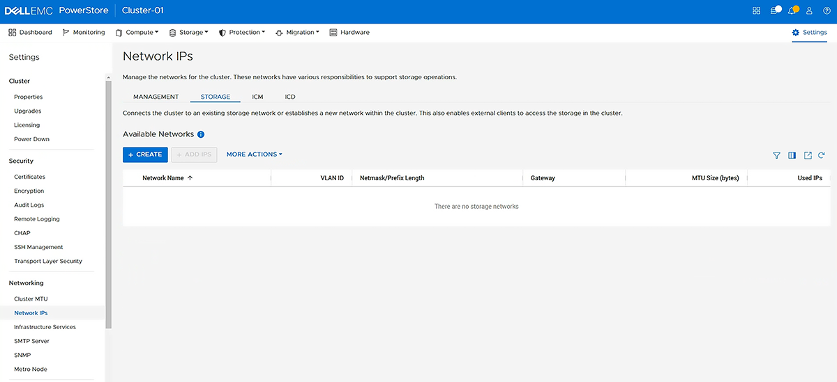
- Enter the Storage Network details in the fields provided, and then click Next.
Figure 180. Storage Network details screen 
- Select the 10 GbE interfaces for each storage processor, and then click Finish.
Figure 181. Storage Interfaces screen 