

Assets

Introducing APEX Navigator for Kubernetes: Resource onboarding

Mon, 20 May 2024 17:00:00 -0000
|Read Time: 0 minutes
We are excited to announce the availability of Dell APEX Navigator for Kubernetes! This offering is part of the Dell Premier account experience that includes the APEX Navigator user interface and shares the management interface with APEX Navigator for Storage. In a three-part blog series, we will go through the key aspects of the APEX Navigator for Kubernetes:
- Onboarding Kubernetes clusters and storage resources
- Batch deployment of Container Storage Modules
- Application Mobility between clusters
UI Overview
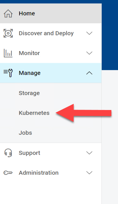
Once you login as an ITOPs user, you can navigate to the Kubernetes section under Manage section of the left side navigation bar:
The details pane has four tabs:
- The Clusters tab shows the onboarded Kubernetes clusters in a tabular form with various attributes of the clusters as columns. You can add additional clusters and manage the container storage modules.
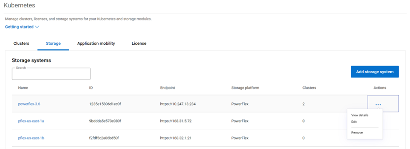
- Similarly the Storage tab shows the storage platforms onboarded.
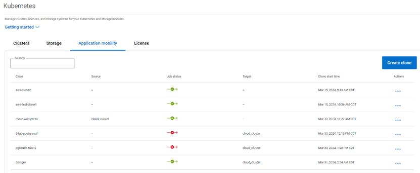
- The Application Mobility section shows the Application Mobility jobs that have been initiated along with details like Source destination and the status of the job.
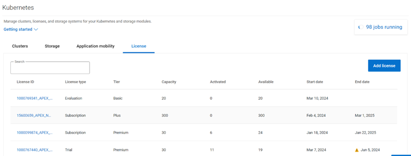
- The License tab lists the various licenses that have been added to the platform.
Multi-cloud Kubernetes Cluster onboarding
Kubernetes clusters both on-prem and on public clouds can be managed with APEX Navigator for Kubernetes.
Onboarding prerequisites
Before you onboard a cluster, please go through the following steps to make sure the cluster is ready to be onboarded.
Install the latest Dell CSM-operator
Dell CSM Operator is a Kubernetes Operator designed to manage the Dell Storage CSI drivers and Container Storage Modules. Install v1.4.4 or later using the instructions here.
Install the Dell Connectivity Client
The Dell Connectivity Client initiates a connection to https://connect-into.dell.com/ in order to communicate with APEX Navigator for Kubernetes. Therefore, the firewall and proxy between the Kubernetes cluster and that address must be opened.
To do this first make sure the following namespace are created on the cluster:
$ kubectl create namespace karavi dell-csm dell-connectivity-client
You can get the custom resource definition (CRD) YAML file to install the Dell Connectivity Client resource from the CSM Operator GitHub repo. Once you have the YAML file you can install the client service as follows:
$ kubectl apply -f dcm-client.yml
You can verify the installation to see an output like below:
$ kubectl get pods -n dell-connectivity-client
NAME READY STATUS RESTARTS AGE
dell-connectivity-client-0 3/3 Running 0 70s
Note: if you remove a cluster, please note that you need to re-install the Dell client before you onboard it again.
License for the cluster
On the License tab, you can add the different licenses that you have using APEX Navigator for Kubernetes. You will be assigning one of these licenses to the cluster once connected.
Connect to cluster
Once you have the CSM Operator and Dell Connectivity Client running on the cluster, you can connect to the cluster from the APEX Navigator UI. Here are the steps involved in establishing trust between the APEX Navigator and the Kubernetes cluster to onboard the cluster.
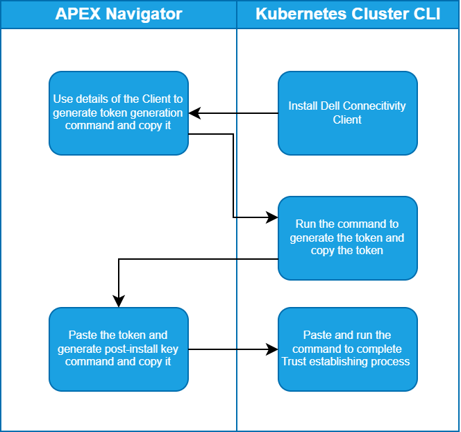
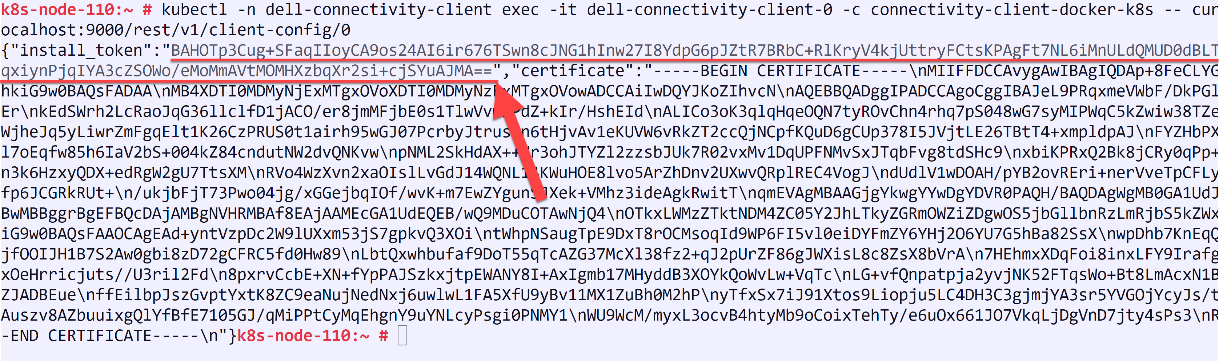
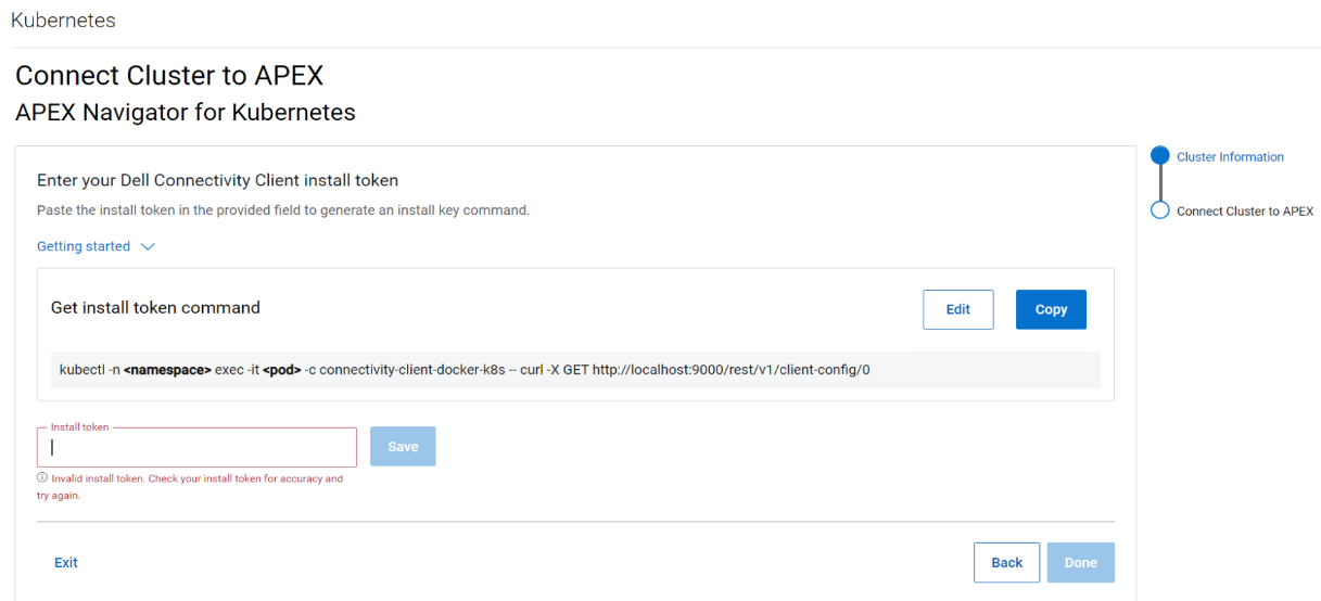
Follow the instructions on the UI to create the command that you need to run on your cluster to generate a token and then copy the token (underlined in the figure below) and paste it in the Install token field:
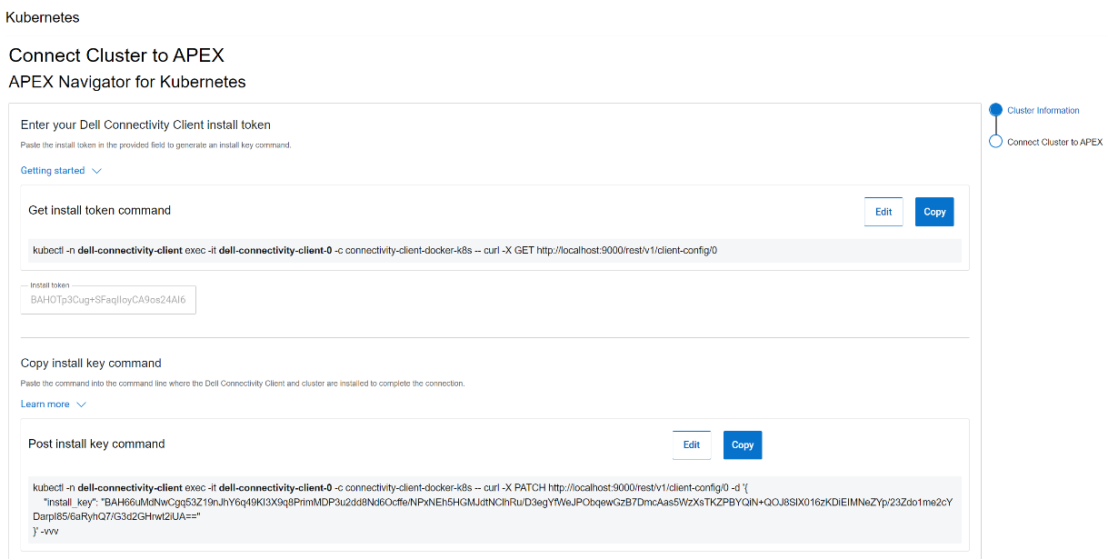
After this step, another command is generated that needs to be run on the cluster to complete the trusted connection process, as show in the following figure:
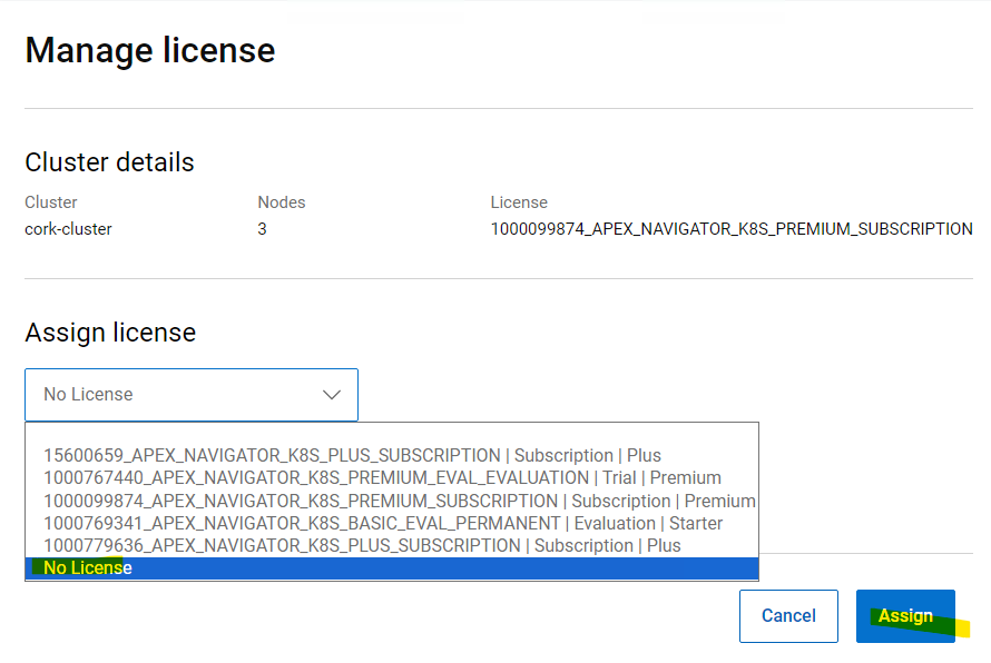
License for the cluster
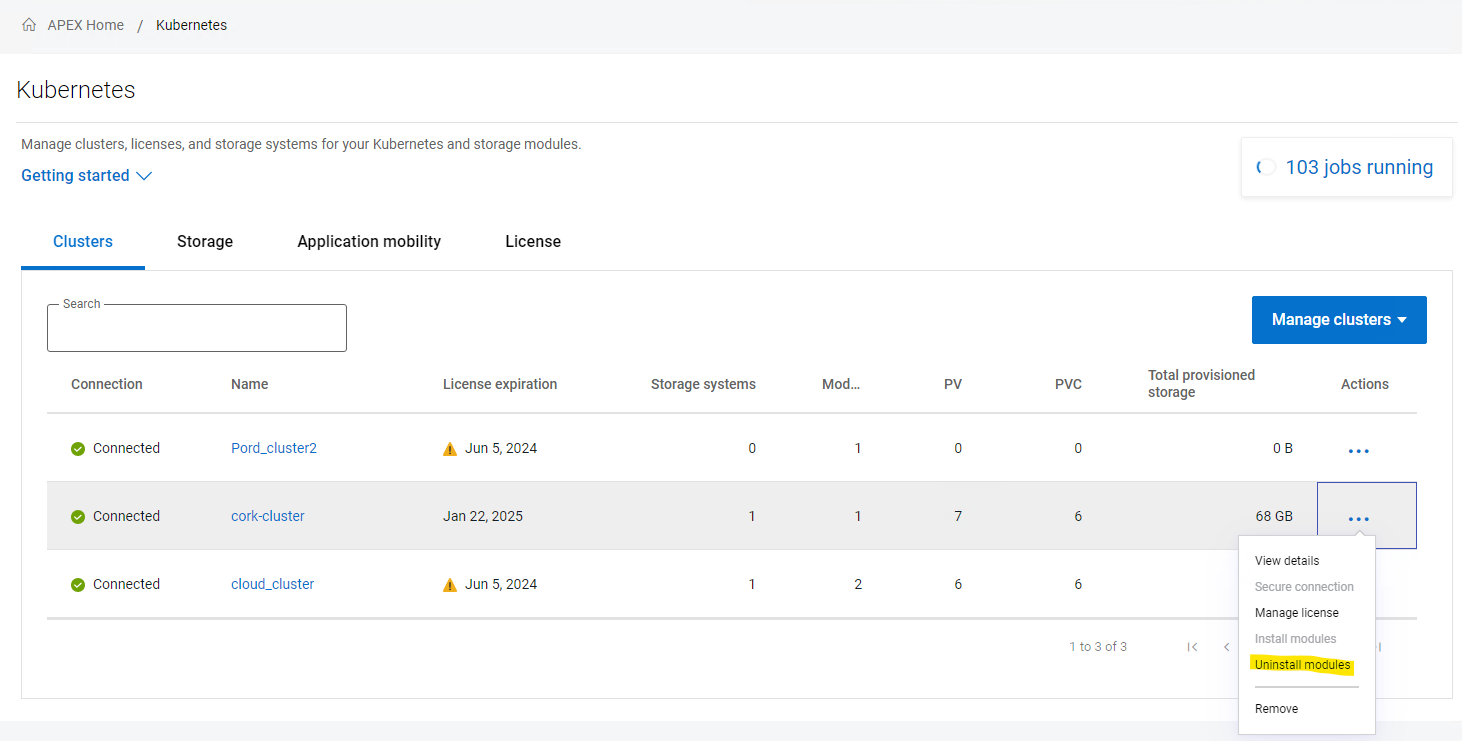
Once the cluster successfully connects, you may see the cluster is still listed in grey color indicating that it requires a license. Click on the ellipsis (…) button under the Actions column, on the right-hand side of the cluster row and select “Manage license”. In the License selection dialog, you can select the License that you want to assign the cluster. This step completes the onboarding of the cluster.
Removing a cluster
Following are the steps to remove a Kubernetes cluster from APEX Navigator for Kubernetes:
1. Uninstall all modules:
2. Unassign the license

3. Remove the cluster from the interface.

4. Uninstall the connectivity client on your cluster:
kubectl delete -n dell-connectivity-client apexconnectivityclients
After these four steps, the cluster is cleaned from every Dell CSI/CSM/APEX Navigator resource.
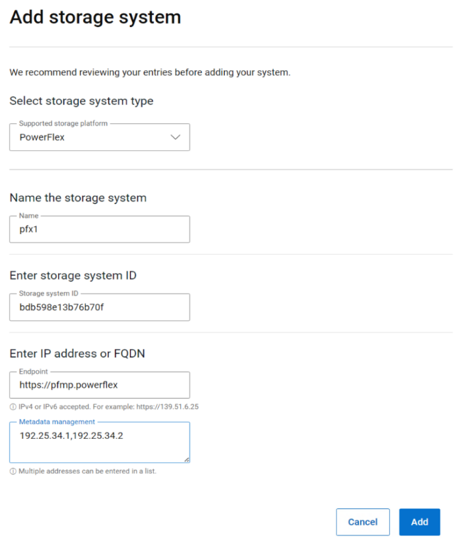
Multi cloud Storage support
APEX Navigator for Kubernetes supports both on-prem and on-cloud Dell storage platforms. On-prem storage systems can be added using a simple dialog as shown below:
APEX Block storage on AWS
If you would like to use APEX Block storage on AWS, please make sure you have the required licenses for APEX Navigator for Storage and have onboarded your AWS account onto the APEX Navigator platform. You can deploy an APEX Block Storage cluster on AWS with just a few clicks (watch this demo video on YouTube) and start using the cloud storage for Kubernetes
Authors:
Parasar Kodati, Engineering Technologist, Dell ISG
Florian Coulombel, Engineering Technologist, Dell ISG

Introducing APEX Navigator for Kubernetes: Batch deployment of CSMs
Mon, 20 May 2024 17:00:00 -0000
|Read Time: 0 minutes
This is part 2 of the three-part blog post series introducing Dell APEX Navigator for Kubernetes. In this post, we will cover batch deployment of CSMs on any number of onboarded Kubernetes clusters.
A major advantage of using APEX Navigator for Kubernetes is the ability to deploy multiple CSMs onto multiple Kubernetes clusters which consume storage from different Dell storage systems (including Dell APEX Block Storage on AWS). Multiple install jobs are simultaneously launched on the clusters to enable parallel installation which saves time and effort for admins managing storage for a growing Kubernetes footprint. Let us see how this can be achieved.
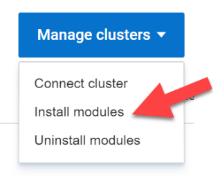
From the Clusters tab click on Manage Clusters and select Install modules:
This launches the Module Installation wizard where you can install specific Dell Container Storage Modules and things like SDC client for PowerFlex storage for an entire set of clusters. This ensures the same storage class and other configuration parameters are used across all the clusters for consistency and standardization. In the first release of APEX Navigator for Kubernetes, only Observability, Authorization, and Application Mobility CSMs are supported. Over time more services will be added.
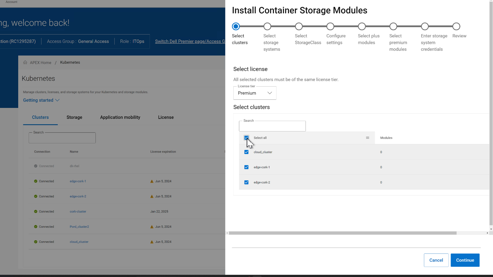
In the CSM deployment wizard, the first step is to select all the clusters where the CSMs need to be installed.
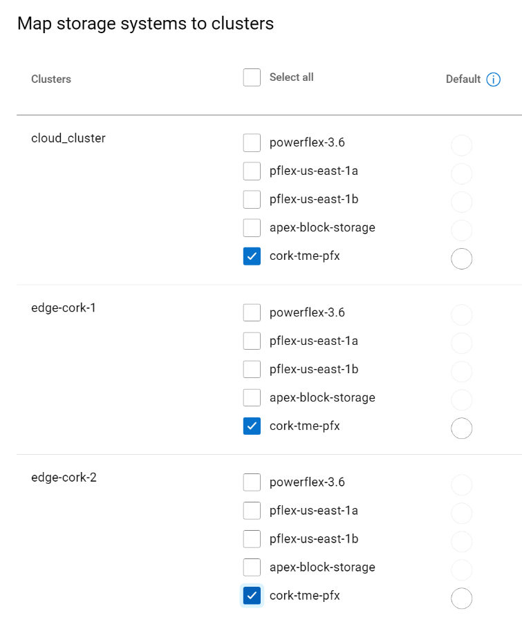
Then, you can select the storage systems for each of the clusters. In the figure below, the selected clusters are sharing the same storage.
In the next step, the Storage class is set for each cluster pair:
- Select the CSMs to install under Plus and Premium categories.
- Enter storage credentials for the storage platforms.
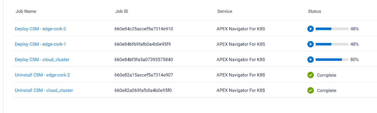 On the summary page of the wizard, you can review the install configurations and click Install to start the installation process. You can track the multiple parallel install jobs on multiple clusters:
Authors:
Parasar Kodati, Engineering Technologist, Dell ISG
Florian Coulombel, Engineering Technologist, Dell ISG

Introducing APEX Navigator for Kubernetes: Application Mobility
Mon, 20 May 2024 17:00:00 -0000
|Read Time: 0 minutes
This is part 3 of the three-part blog series introducing Dell APEX Navigator for Kubernetes.
Application Mobility Overview
Data and application mobility is an essential element in maintaining the required availability and service level for a given application. From a workload standpoint, the application needs to have a redundant instance at a target site that can be used as a failover instance. For this to work for stateful applications, we need to ensure data availability on the target site. Data mobility can be achieved in two ways:
- Continuous replication at the storage level using the Replication Container Storage Module
- Point-in-time host-based backup using the Application Mobility Container Storage Module
The Replication container storage module for Dell storage platforms orchestrates the data replication using the storage platform’s native replication capabilities. The Application Mobility module on the other hand uses the host-based backup approach. While both the approaches work for Dell storage platforms through the command line interface, the first release of APEX Navigator for Kubernetes user interface supports only the host-based backup functionality called the Application Mobility Module.
The following are the pre-requisites for application mobility:
- Source and target K8s clusters onboarded and Application Mobility CSM installed.
- Source and target Dell storage systems onboarded.
- S3 Object Store accessible from source and target for the intermediate backup copy of the application data
Adding Object Store
We already covered how to connect clusters and storage in previous sections. Let us see how to set up the S3 Object Store within the APEX Navigator for Kubernetes.
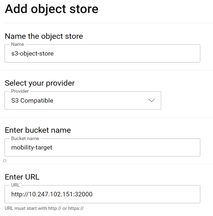
Navigate to the Storage tab and click on the “Add object store” button. This launches a dialog to add the details of the Object store:
If using Amazon Web services (AWS) S3 for the object store, the region on the Kubernetes backup storage location object needs to be updated prior to creating a clone. On each Kubernetes cluster where Application Mobility is installed, run this command to update the region:
kubectl patch backupstoragelocation/default -n dell-csm --type='merge' -p '{"spec":{"config":{"region":"<region- name>"}}}'
Application Mobility definition
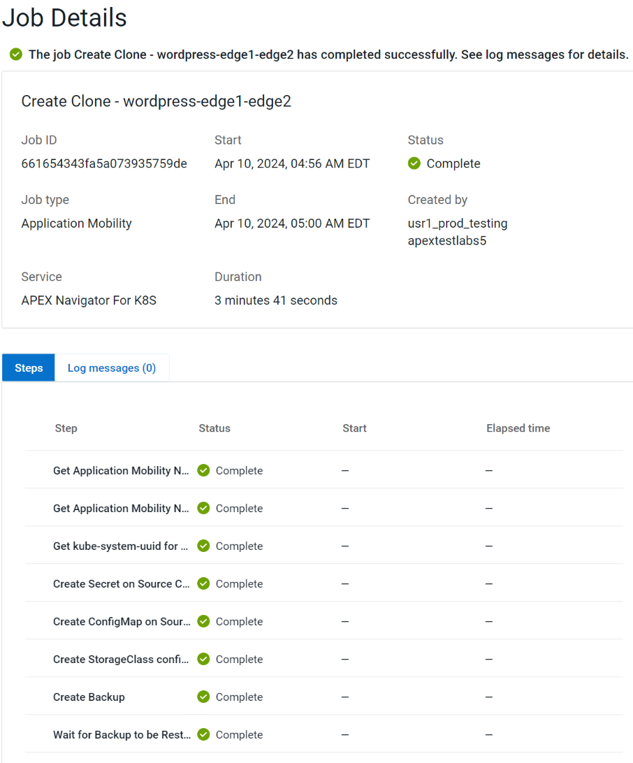
To start an Application mobility job, go to the Application Mobility tab and click “Create Clone”. This launches a wizard that takes you through the following steps:
- Specify source cluster and the namespace of the application to be moved.
- Specify target cluster and the namespace.
- Specify the Object store details to be used for the intermediate backup copy.
- Review details and click Create clone to start the mobility job.
You can track mobility jobs under Jobs section like below:
Authors:
Parasar Kodati, Engineering Technologist, Dell ISG
Florian Coulombel, Engineering Technologist, Dell ISG

For the Year 2022: Ansible Integration Enhancements for the Dell Infrastructure Solutions Portfolio
Mon, 29 Apr 2024 19:20:40 -0000
|Read Time: 0 minutes
The Dell infrastructure portfolio spans the entire hybrid cloud, from storage to compute to networking, and all the software functionality to deploy, manage, and monitor different application stacks from traditional databases to containerized applications deployed on Kubernetes. When it comes to integrating the infrastructure portfolio with 3rd party IT Operations platforms, Ansible is at the top of the list in terms of expanding the scope and depth of integration.
Here is a summary of the enhancements we made to the various Ansible modules across the Dell portfolio in 2022:
- Ansible plugin for PowerStore had four different releases (1.5,1.6,1.7, and 1.8) with the following capabilities:
- New modules:
- dellemc.powerstore.ldap_account – To manage LDAP account on Dell PowerStore
- dellemc.powerstore.ldap_domain - To manage LDAP domain on Dell PowerStore
- dellemc.powerstore.dns - To manage DNS on Dell PowerStore
- dellemc.powerstore.email - To manage email on Dell PowerStore
- dellemc.powerstore.ntp - To manage NTP on Dell PowerStore
- dellemc.powerstore.remote_support – To manage remote support to get the details, modify the attributes, verify the connection. and send a test alert
- dellemc.powerstore.remote_support_contact – To manage remote support contact on Dell PowerStore
- dellemc.powerstore.smtp_config – To manage SMTP config
- Added support for the host connectivity option to host and host group
- Added support for cluster creation and validating cluster creation attributes
- Data operations:
- Added support to clone, refresh, and restore a volume
- Added support to configure/remove the metro relationship for a volume
- Added support to modify the role of replication sessions
- Added support to clone, refresh, and restore a volume group
- File system:
- Added support to associate/disassociate a protection policy to/from a NAS server
- Added support to handle filesystem and NAS server replication sessions
- Ansible execution:
- Added an execution environment manifest file to support building an execution environment with Ansible Builder
- Enabled check_mode support for Info modules
- Updated modules to adhere to Ansible community guidelines
- The Info module is enhanced to list DNS servers, email notification destinations, NTP servers, remote support configuration, remote support contacts and SMTP configuration, LDAP domain, and LDAP accounts.
- Visit this GitHub page to go through release history: https://github.com/dell/ansible-powerstore/blob/main/CHANGELOG.rst
- New modules:
- Ansible plugin for PowerFlex had four different releases (1.2, 1.3, 1.4, and 1.5) with the following capabilities:
- New modules:
- dellemc.powerflex.replication_consistency_group – To manage replication consistency groups on Dell PowerFlex
- dellemc.powerflex.mdm_cluster – To manage a MDM cluster on Dell PowerFlex
- dellemc.powerflex.protection_domain – To manage a Protection Domain on Dell PowerFlex
- The info module is enhanced to support listing the replication consistency groups, volumes, and storage pools with the statistics data.
- Storage management:
- The storage pool module is enhanced to get the details with the statistics data.
- The volume module is enhanced to get the details with the statistics data.
- Ansible execution:
- Added an execution environment manifest file to support building an execution environment with Ansible Builder
- Enabled check_mode support for the Info module
- Updated modules to adhere to Ansible community guidelines
- Visit this GitHub page to go through release history: https://github.com/dell/ansible-powerflex/blob/main/CHANGELOG.rst
- New modules:
- The Ansible plugin for PowerMax had four different releases (1.7, 1.8, 2.0 and 2.1) with the following capabilities:
- New module: dellemc.powermax.initiator – To manage initiators
- Host operations:
- Added support of case insensitivity of the host WWN to the host, and to the masking view module.
- Enhanced the host module to add or remove initiators to or from the host using an alias.
- Data operations:
- Enhanced storage group module to support
- Moving volumes to destination storage groups.
- Making volume name an optional parameter while adding a new volume to a storage group.
- Setting host I/O limits for existing storage groups and added the ability to force move devices between storage groups with SRDF protection.
- Enhanced volume module to support
- A cylinders option to specify size while creating a LUN, and added the ability to create volumes with identifier_name and volume_id.
- Renaming volumes that were created without a name.
- Enhanced the RDF group module to get volume pair information for an SRDF group.
- Enhanced storage group module to support
- Added an execution environment manifest file to support building an execution environment with Ansible Builder
- Added rotating file handler for log files
- Enhanced the info module to list the initiators, get volume details and masking view connection information
- Enhanced the verifycert parameter in all modules to support file paths for custom certificate location.
- Some things renamed:
- Names of previously released modules have been changed from dellemc_powermax_<module name> to <module name>
- The Gatherfacts module is renamed to Info
- Renamed metro DR module input parameters
- Visit this GitHub page to go through release history: https://github.com/dell/ansible-powermax/blob/main/CHANGELOG.rst
- Ansible plugin for PowerScale had four different releases (1.5,1.6,1.7 and 1.8) with the following capabilities:
- New modules:
- dellemc.powerscale.nfs_alias – To manage NFS aliases on a PowerScale
- dellemc.powerscale.filepoolpolicy – To manage the file pool policy on PowerScale
- dellemc.powerscale.storagepooltier – To manage storage pool tiers on PowerScale
- dellemc.powerscale.networksettings – To manage Network settings on PowerScale
- dellemc.powerscale.smartpoolsettings – To manage Smartpool settings on PowerScale
- Security support:
- Support for security flavors while creating and modifying NFS export.
- Access Zone, SMB, SmartQuota, User and Group modules are enhanced to support the NIS authentication provider.
- The Filesystem module is enhanced to support ACL and container parameters.
- The ADS module is enhanced to support the machine_account and organizational_unit parameters while creating an ADS provider.
- File management:
- The Info module is enhanced to support the listing of NFS aliases.
- Support to create and modify additional parameters of an SMB share in the SMB module.
- Support for recursive force deletion of filesystem directories.
- Ansible execution
- Added an execution environment manifest file to support building an execution environment with Ansible Builder.
- Check mode is supported for the Info, Filepool Policy, and Storagepool Tier modules.
- Added rotating file handlers for log files.
- Removal of the dellemc_powerscale prefix from all module names.
- Other module enhancements:
- The SyncIQ Policy module is enhanced to support accelerated_failback and restrict_target_network of a policy.
- The Info module is enhanced to support NodePools and Storagepool Tiers Subsets.
- The SmartQuota module is enhanced to support container parameter and float values for Quota Parameters.
- Visit this GitHub page to go through release history: https://github.com/dell/ansible- powerscale/blob/main/CHANGELOG.rst
- New modules:
- The Ansible plugin for Dell OpenManage had 13 releases this year, some of which were major releases. Here is a brief summary:
- v7.1: Support for retrieving smart fabric and smart fabric uplink information, support for IPv6 addresses for OMSDK dependent iDRAC modules, and OpenManage Enterprise inventory plugin.
- v7.0: Rebranded from Dell EMC to Dell, enhanced the idrac_firmware module to support proxy, and added support to retrieve iDRAC local user details.
- v6.3: Support for the LockVirtualDisk operation and to configure Remote File Share settings using the idrac_virtual_media module.
- v6.2: Added clear pending BIOS attributes, reset BIOS to default settings, and configured BIOS attributes using Redfish enhancements for idrac_bios.
- v6.1: Support for device-specific operations on OpenManage Enterprise and configuring boot settings on iDRAC.
- v6.0: Added collection metadata for creating execution environments, deprecation of share parameters, and support for configuring iDRAC attributes using the idrac_attributes module.
- v5.5: Support to generate certificate signing request, import, and export certificates on iDRAC.
- v5.4: Enhanced the idrac_server_config_profile module to support export, import, and preview of the SCP configuration using Redfish and added support for check mode.
- v5.3: Added check mode support for redfish_storage_volume, idempotency for the ome_smart_fabric_uplink module, and support for debug logs added to ome_diagnostics
- V5.2: Support to configure console preferences on OpenManage Enterprise.
- V5.1: Support for OpenManage Enterprise Modular server interface management.
- V5.0.1: Support to provide custom or organizational CA signed certificates for SSL validation from the environment variable.
- 5.0: HTTPS SSL support for all modules and quick deploy settings.
- Visit this GitHub page to go through release history: https://github.com/dell/dellemc-openmanage-ansible-modules/releases.
For all Ansible projects you can track the progress, contribute, or report issues on individual repositories.
You can also join our DevOps and Automation community at: https://www.dell.com/community/Automation/bd-p/Automation.
Happy New Year and happy upgrades!
Authors: Parasar Kodati and Florian Coulombel

Network Design for PowerScale CSI
Mon, 29 Apr 2024 18:55:46 -0000
|Read Time: 0 minutes
Network connectivity is an essential part of any infrastructure architecture. When it comes to how Kubernetes connects to PowerScale, there are several options to configure the Container Storage Interface (CSI). In this post, we will cover the concepts and configuration you can implement.
The story starts with CSI plugin architecture.
CSI plugins
Like all other Dell storage CSI, PowerScale CSI follows the Kubernetes CSI standard by implementing functions in two components.
- CSI controller plugin
- CSI node plugin
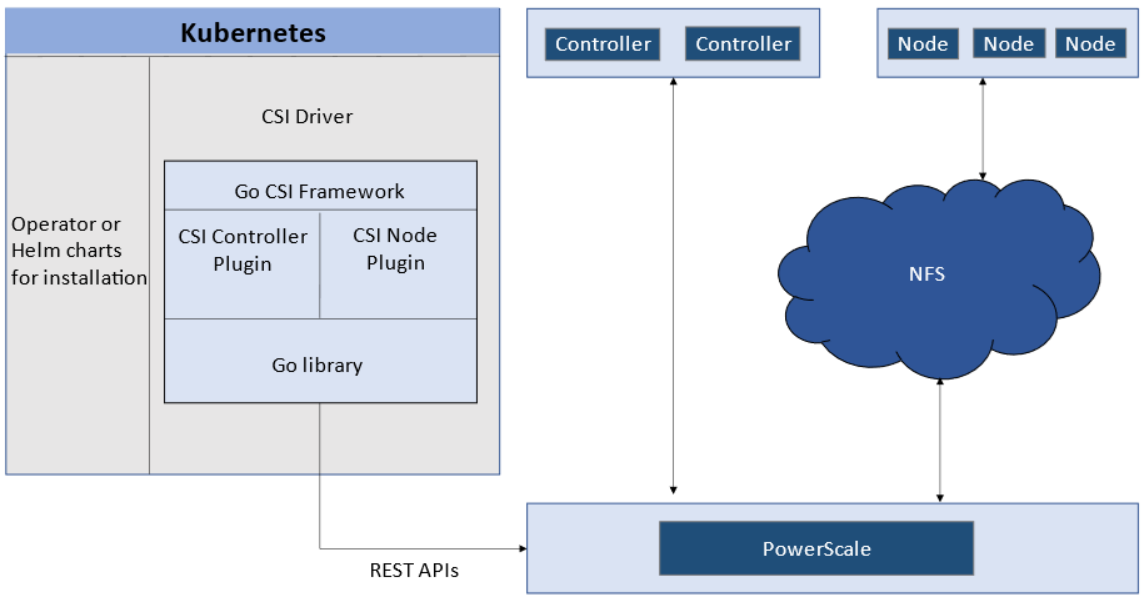
The CSI controller plugin is deployed as a Kubernetes Deployment, typically with two or three replicas for high-availability, with only one instance acting as a leader. The controller is responsible for communicating with PowerScale, using Platform API to manage volumes (to PowerScale it’s to create/delete directories, NFS exports, and quotas), to update the NFS client list when a Pod moves, and so on.
A CSI node plugin is a Kubernetes DaemonSet, running on all nodes by default. It’s responsible for mounting the NFS export from PowerScale, to map the NFS mount path to a Pod as persistent storage, so that applications and users in the Pod can access the data on PowerScale.
Roles, privileges, and access zone
Because CSI needs to access both PAPI (PowerScale Platform API) and NFS data, a single user role typically isn’t secure enough: the role for PAPI access will need more privileges than normal users.
According to the PowerScale CSI manual, CSI requires a user that has the following privileges to perform all CSI functions:
Privilege | Type |
ISI_PRIV_LOGIN_PAPI | Read Only |
ISI_PRIV_NFS | Read Write |
ISI_PRIV_QUOTA | Read Write |
ISI_PRIV_SNAPSHOT | Read Write |
ISI_PRIV_IFS_RESTORE | Read Only |
ISI_PRIV_NS_IFS_ACCESS | Read Only |
ISI_PRIV_IFS_BACKUP | Read Only |
Among these privileges, ISI_PRIV_SNAPSHOT and ISI_PRIV_QUOTA are only available in the System zone. And this complicates things a bit. To fully utilize these CSI features, such as volume snapshot, volume clone, and volume capacity management, you have to allow the CSI to be able to access the PowerScale System zone. If you enable the CSM for replication, the user needs the ISI_PRIV_SYNCIQ privilege, which is a System-zone privilege too.
By contrast, there isn’t any specific role requirement for applications/users in Kubernetes to access data: the data is shared by the normal NFS protocol. As long as they have the right ACL to access the files, they are good. For this data accessing requirement, a non-system zone is suitable and recommended.
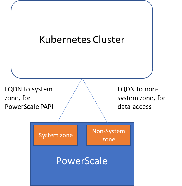
These two access zones are defined in different places in CSI configuration files:
- The PAPI access zone name (FQDN) needs to be set in the secret yaml file as “endpoint”, for example “f200.isilon.com”.
- The data access zone name (FQDN) needs to be set in the storageclass yaml file as “AzServiceIP”, for example “openshift-data.isilon.com”.
If an admin really cannot expose their System zone to the Kubernetes cluster, they have to disable the snapshot and quota features in the CSI installation configuration file (values.yaml). In this way, the PAPI access zone can be a non-System access zone.
The following diagram shows how the Kubernetes cluster connects to PowerScale access zones.
Network
Normally a Kubernetes cluster comes with many networks: a pod inter-communication network, a cluster service network, and so on. Luckily, the PowerScale network doesn’t have to join any of them. The CSI pods can access a host’s network directly, without going through the Kubernetes internal network. This also has the advantage of providing a dedicated high-performance network for data transfer.
For example, on a Kubernetes host, there are two NICs: IP 192.168.1.x and 172.24.1.x. NIC 192.168.1.x is used for Kubernetes, and is aligned with its hostname. NIC 172.24.1.x isn’t managed by Kubernetes. In this case, we can use NIC 172.24.1.x for data transfer between Kubernetes hosts and PowerScale.
Because by default, the CSI driver will use the IP that is aligned with its hostname, to let CSI recognize the second NIC 172.24.1.x, we have explicitly set the IP range in “allowedNetworks” in the values.yaml file in the CSI driver installation. For example:
allowedNetworks: [172.24.1.0/24]
Also, in this network configuration, it’s unlikely that the Kubernetes internal DNS can resolve the PowerScale FQDN. So, we also have to make sure the “dnsPolicy” has been set to “ClusterFirstWithHostNet” in the values.yaml file. With this dnsPolicy, the CSI pods will reach the DNS server in /etc/resolv.conf in the host OS, not the internal DNS server of Kubernetes.
The following diagram shows the configuration mentioned above:
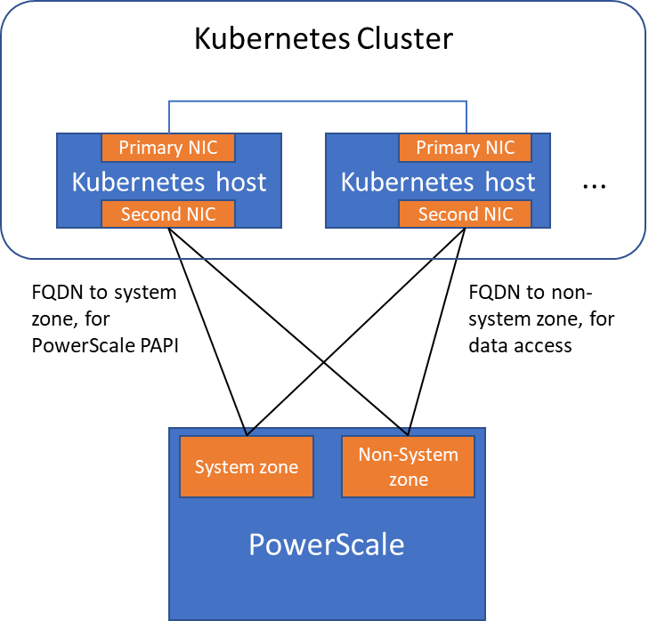
Please note that the “allowedNetworks” setting only affects the data access zone, and not the PAPI access zone. In fact, CSI just uses this parameter to decide which host IP should be set as the NFS client IP on the PowerScale side.
Regarding the network routing, CSI simply follows the OS route configuration. Because of that, if we want the PAPI access zone to go through the primary NIC (192.168.1.x), and have the data access zone to go through the second NIC (172.24.1.x), we have to change the route configuration of the Kubernetes host, not this parameter.
Hopefully this blog helps you understand the network configuration for PowerScale CSI better. Stay tuned for more information on Dell Containers & Storage!
Authors: Sean Zhan, Florian Coulombel

Network Design for PowerScale CSI
Mon, 29 Apr 2024 18:53:12 -0000
|Read Time: 0 minutes
Network connectivity is an essential part of any infrastructure architecture. When it comes to how Kubernetes connects to PowerScale, there are several options to configure the Container Storage Interface (CSI). In this post, we will cover the concepts and configuration you can implement.
The story starts with CSI plugin architecture.
CSI plugins
Like all other Dell storage CSI, PowerScale CSI follows the Kubernetes CSI standard by implementing functions in two components.
- CSI controller plugin
- CSI node plugin
The CSI controller plugin is deployed as a Kubernetes Deployment, typically with two or three replicas for high-availability, with only one instance acting as a leader. The controller is responsible for communicating with PowerScale, using Platform API to manage volumes (to PowerScale it’s to create/delete directories, NFS exports, and quotas), to update the NFS client list when a Pod moves, and so on.
A CSI node plugin is a Kubernetes DaemonSet, running on all nodes by default. It’s responsible for mounting the NFS export from PowerScale, to map the NFS mount path to a Pod as persistent storage, so that applications and users in the Pod can access the data on PowerScale.
Roles, privileges, and access zone
Because CSI needs to access both PAPI (PowerScale Platform API) and NFS data, a single user role typically isn’t secure enough: the role for PAPI access will need more privileges than normal users.
According to the PowerScale CSI manual, CSI requires a user that has the following privileges to perform all CSI functions:
Privilege | Type |
ISI_PRIV_LOGIN_PAPI | Read Only |
ISI_PRIV_NFS | Read Write |
ISI_PRIV_QUOTA | Read Write |
ISI_PRIV_SNAPSHOT | Read Write |
ISI_PRIV_IFS_RESTORE | Read Only |
ISI_PRIV_NS_IFS_ACCESS | Read Only |
ISI_PRIV_IFS_BACKUP | Read Only |
Among these privileges, ISI_PRIV_SNAPSHOT and ISI_PRIV_QUOTA are only available in the System zone. And this complicates things a bit. To fully utilize these CSI features, such as volume snapshot, volume clone, and volume capacity management, you have to allow the CSI to be able to access the PowerScale System zone. If you enable the CSM for replication, the user needs the ISI_PRIV_SYNCIQ privilege, which is a System-zone privilege too.
By contrast, there isn’t any specific role requirement for applications/users in Kubernetes to access data: the data is shared by the normal NFS protocol. As long as they have the right ACL to access the files, they are good. For this data accessing requirement, a non-system zone is suitable and recommended.
These two access zones are defined in different places in CSI configuration files:
- The PAPI access zone name (FQDN) needs to be set in the secret yaml file as “endpoint”, for example “f200.isilon.com”.
- The data access zone name (FQDN) needs to be set in the storageclass yaml file as “AzServiceIP”, for example “openshift-data.isilon.com”.
If an admin really cannot expose their System zone to the Kubernetes cluster, they have to disable the snapshot and quota features in the CSI installation configuration file (values.yaml). In this way, the PAPI access zone can be a non-System access zone.
The following diagram shows how the Kubernetes cluster connects to PowerScale access zones.
Network
Normally a Kubernetes cluster comes with many networks: a pod inter-communication network, a cluster service network, and so on. Luckily, the PowerScale network doesn’t have to join any of them. The CSI pods can access a host’s network directly, without going through the Kubernetes internal network. This also has the advantage of providing a dedicated high-performance network for data transfer.
For example, on a Kubernetes host, there are two NICs: IP 192.168.1.x and 172.24.1.x. NIC 192.168.1.x is used for Kubernetes, and is aligned with its hostname. NIC 172.24.1.x isn’t managed by Kubernetes. In this case, we can use NIC 172.24.1.x for data transfer between Kubernetes hosts and PowerScale.
Because by default, the CSI driver will use the IP that is aligned with its hostname, to let CSI recognize the second NIC 172.24.1.x, we have explicitly set the IP range in “allowedNetworks” in the values.yaml file in the CSI driver installation. For example:
allowedNetworks: [172.24.1.0/24]
Also, in this network configuration, it’s unlikely that the Kubernetes internal DNS can resolve the PowerScale FQDN. So, we also have to make sure the “dnsPolicy” has been set to “ClusterFirstWithHostNet” in the values.yaml file. With this dnsPolicy, the CSI pods will reach the DNS server in /etc/resolv.conf in the host OS, not the internal DNS server of Kubernetes.
The following diagram shows the configuration mentioned above:
Please note that the “allowedNetworks” setting only affects the data access zone, and not the PAPI access zone. In fact, CSI just uses this parameter to decide which host IP should be set as the NFS client IP on the PowerScale side.
Regarding the network routing, CSI simply follows the OS route configuration. Because of that, if we want the PAPI access zone to go through the primary NIC (192.168.1.x), and have the data access zone to go through the second NIC (172.24.1.x), we have to change the route configuration of the Kubernetes host, not this parameter.
Hopefully this blog helps you understand the network configuration for PowerScale CSI better. Stay tuned for more information on Dell Containers & Storage!
Authors: Sean Zhan, Florian Coulombel

Network Design for PowerScale CSI
Mon, 29 Apr 2024 18:52:07 -0000
|Read Time: 0 minutes
Network connectivity is an essential part of any infrastructure architecture. When it comes to how Kubernetes connects to PowerScale, there are several options to configure the Container Storage Interface (CSI). In this post, we will cover the concepts and configuration you can implement.
The story starts with CSI plugin architecture.
CSI plugins
Like all other Dell storage CSI, PowerScale CSI follows the Kubernetes CSI standard by implementing functions in two components.
- CSI controller plugin
- CSI node plugin
The CSI controller plugin is deployed as a Kubernetes Deployment, typically with two or three replicas for high-availability, with only one instance acting as a leader. The controller is responsible for communicating with PowerScale, using Platform API to manage volumes (to PowerScale it’s to create/delete directories, NFS exports, and quotas), to update the NFS client list when a Pod moves, and so on.
A CSI node plugin is a Kubernetes DaemonSet, running on all nodes by default. It’s responsible for mounting the NFS export from PowerScale, to map the NFS mount path to a Pod as persistent storage, so that applications and users in the Pod can access the data on PowerScale.
Roles, privileges, and access zone
Because CSI needs to access both PAPI (PowerScale Platform API) and NFS data, a single user role typically isn’t secure enough: the role for PAPI access will need more privileges than normal users.
According to the PowerScale CSI manual, CSI requires a user that has the following privileges to perform all CSI functions:
Privilege | Type |
ISI_PRIV_LOGIN_PAPI | Read Only |
ISI_PRIV_NFS | Read Write |
ISI_PRIV_QUOTA | Read Write |
ISI_PRIV_SNAPSHOT | Read Write |
ISI_PRIV_IFS_RESTORE | Read Only |
ISI_PRIV_NS_IFS_ACCESS | Read Only |
ISI_PRIV_IFS_BACKUP | Read Only |
Among these privileges, ISI_PRIV_SNAPSHOT and ISI_PRIV_QUOTA are only available in the System zone. And this complicates things a bit. To fully utilize these CSI features, such as volume snapshot, volume clone, and volume capacity management, you have to allow the CSI to be able to access the PowerScale System zone. If you enable the CSM for replication, the user needs the ISI_PRIV_SYNCIQ privilege, which is a System-zone privilege too.
By contrast, there isn’t any specific role requirement for applications/users in Kubernetes to access data: the data is shared by the normal NFS protocol. As long as they have the right ACL to access the files, they are good. For this data accessing requirement, a non-system zone is suitable and recommended.
These two access zones are defined in different places in CSI configuration files:
- The PAPI access zone name (FQDN) needs to be set in the secret yaml file as “endpoint”, for example “f200.isilon.com”.
- The data access zone name (FQDN) needs to be set in the storageclass yaml file as “AzServiceIP”, for example “openshift-data.isilon.com”.
If an admin really cannot expose their System zone to the Kubernetes cluster, they have to disable the snapshot and quota features in the CSI installation configuration file (values.yaml). In this way, the PAPI access zone can be a non-System access zone.
The following diagram shows how the Kubernetes cluster connects to PowerScale access zones.
Network
Normally a Kubernetes cluster comes with many networks: a pod inter-communication network, a cluster service network, and so on. Luckily, the PowerScale network doesn’t have to join any of them. The CSI pods can access a host’s network directly, without going through the Kubernetes internal network. This also has the advantage of providing a dedicated high-performance network for data transfer.
For example, on a Kubernetes host, there are two NICs: IP 192.168.1.x and 172.24.1.x. NIC 192.168.1.x is used for Kubernetes, and is aligned with its hostname. NIC 172.24.1.x isn’t managed by Kubernetes. In this case, we can use NIC 172.24.1.x for data transfer between Kubernetes hosts and PowerScale.
Because by default, the CSI driver will use the IP that is aligned with its hostname, to let CSI recognize the second NIC 172.24.1.x, we have explicitly set the IP range in “allowedNetworks” in the values.yaml file in the CSI driver installation. For example:
allowedNetworks: [172.24.1.0/24]
Also, in this network configuration, it’s unlikely that the Kubernetes internal DNS can resolve the PowerScale FQDN. So, we also have to make sure the “dnsPolicy” has been set to “ClusterFirstWithHostNet” in the values.yaml file. With this dnsPolicy, the CSI pods will reach the DNS server in /etc/resolv.conf in the host OS, not the internal DNS server of Kubernetes.
The following diagram shows the configuration mentioned above:
Please note that the “allowedNetworks” setting only affects the data access zone, and not the PAPI access zone. In fact, CSI just uses this parameter to decide which host IP should be set as the NFS client IP on the PowerScale side.
Regarding the network routing, CSI simply follows the OS route configuration. Because of that, if we want the PAPI access zone to go through the primary NIC (192.168.1.x), and have the data access zone to go through the second NIC (172.24.1.x), we have to change the route configuration of the Kubernetes host, not this parameter.
Hopefully this blog helps you understand the network configuration for PowerScale CSI better. Stay tuned for more information on Dell Containers & Storage!
Authors: Sean Zhan, Florian Coulombel

Announcing CSM Release 1.6!
Mon, 29 Apr 2024 18:40:02 -0000
|Read Time: 0 minutes
Introduction
The first release of 2023 for Kubernetes CSI Driver & Dell Container Storage Modules (CSM) is here!
The official changelog is available in the CHANGELOG directory of the CSM repository.
CSI Features
Supported Kubernetes distributions
The newly supported Kubernetes distributions are:
- Kubernetes 1.26
- MKE 3.6
- RKE 1.4
Note: OpenShift 4.12 official qualification is not there yet. Indeed, these modules have been tested against Kubernetes 1.25 which is based on OpenShift 4.12. But you must install them using Helm package manager, not CSI or CSM Operators.
Installation Wizard
One of the major new features for CSI in CSM 1.6 is the Installation Wizard.
If you are a faithful reader of this blog series, you already know that Dell's CSI and CSM moved to pure Helm Charts and are distributed in our helm chart repository. This paved the way for the wizard installer!
Straight from the documentation portal, you can launch the wizard to configure and install the CSI and CSM modules for PowerStore and PowerMax. All the dependencies between CSI and CSM are managed.
The wizard doesn't aim to cover all use cases but gives an excellent default values.yaml, which can always be tuned later.
It has never been easier to install CSI and CSM!
cert-csi open-source
cert-csi is Dell's test framework to validate and qualify drivers against the Kubernetes distributions.
If all tests from cert-csi pass, we call a platform (Linux OS + Kubernetes distribution) certified and officially supported by the Dell Engineering and Support structure.
With cert-csi open-sourced, the community can validate a platform, even if it’s not in the support matrix yet.
For more details about how to use the cert-csi utility, see the documentation portal.
Other features
The dellctl images CLI prints all the container images needed by Dell CSI drivers.
PowerMax Metro volumes are now fully compliant with the CSI specification for volume expansion, clone, and snapshot.
CSM Features
CSM Operator adds PowerStore support
The CSM Operator is the future of the Operator framework for Dell CSI driver and Dell Container Storage Modules and now integrates the modules for PowerStore.
CSM Resiliency PowerStore support
Kubernetes is notably conservative with StatefulSets on node failures: it won't reschedule them automatically and requires an administrator to force the deletion of the pods.
CSM resiliency solves that problem (and more) by querying the backend storage and getting the volumes' status to allow rescheduling in a few seconds after a node is NotReady for Kubernetes.
PowerStore is now part of the supported storage backends!
CSM Replication PowerFlex support
CSM replication supports PowerFlex and it is now possible to combine it with an offering of PowerFlex in AWS. For these types of designs, it is recommended to have low latency between the source and the target. For example, here is the architecture of our lab:
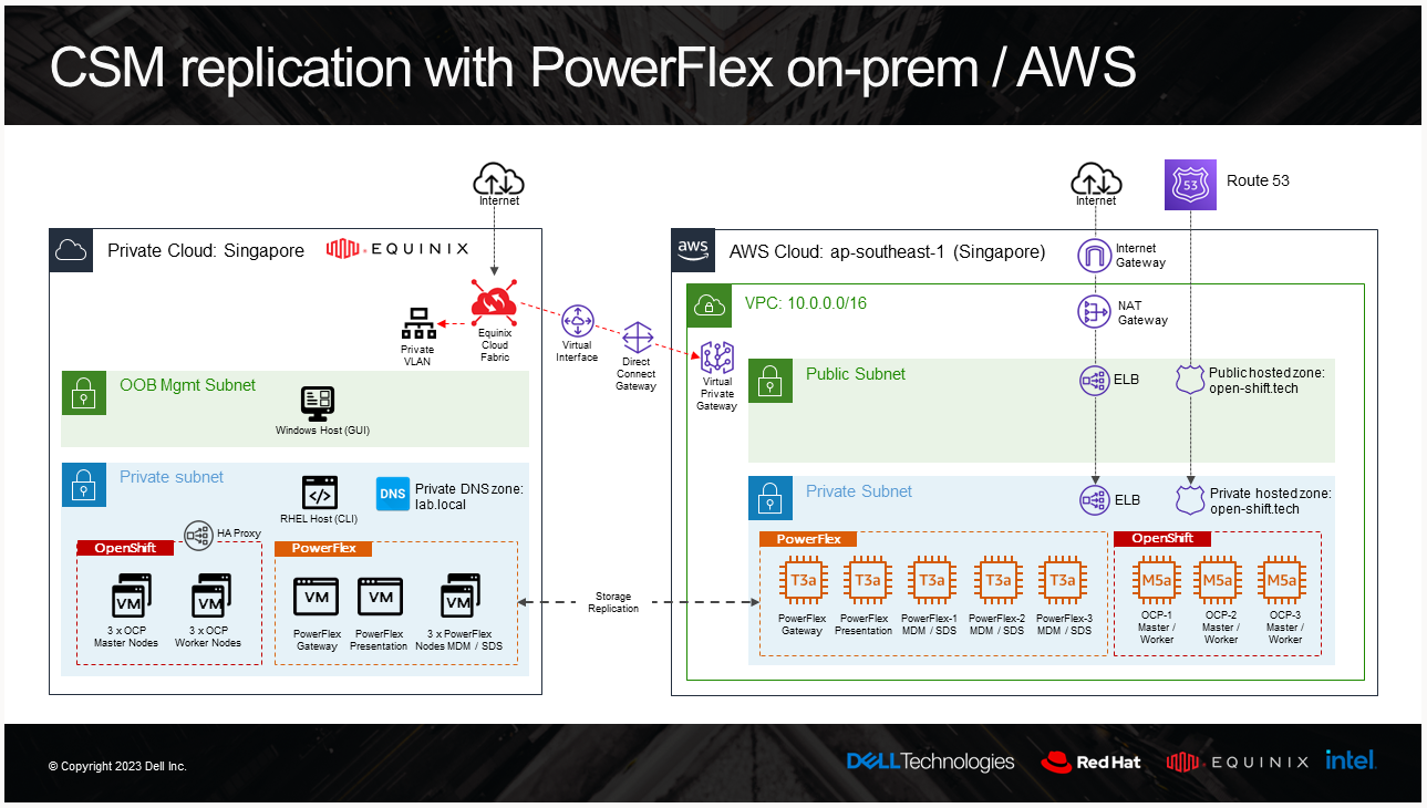
And the result of a replicated volume in PowerFlex UI in AWS looks like this:
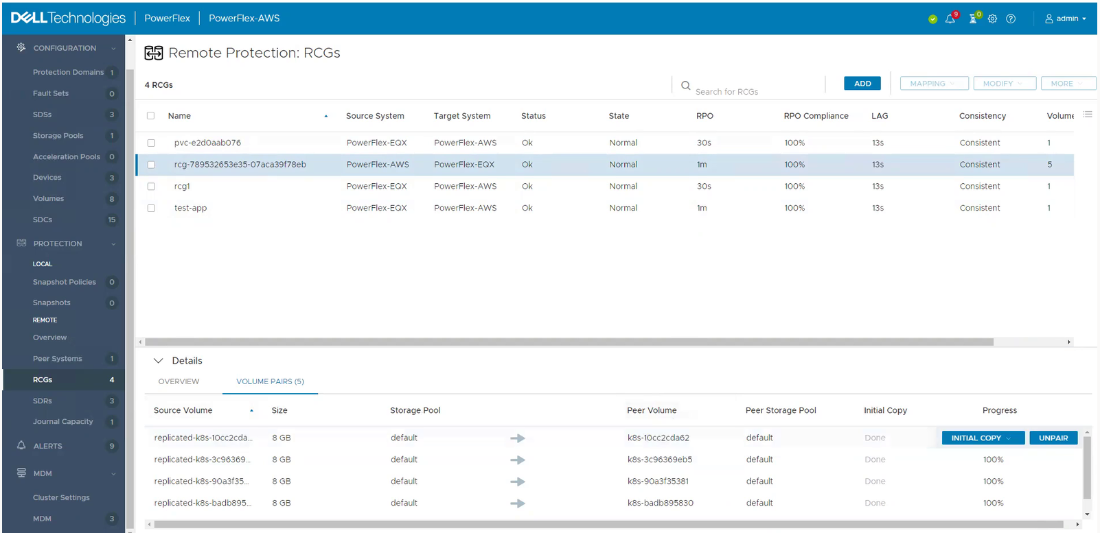
To learn more about PowerFlex in AWS, see the video Dell Project Alpine Gets Real with PowerFlex on AWS and the blog Dell PowerFlex is now available on AWS.
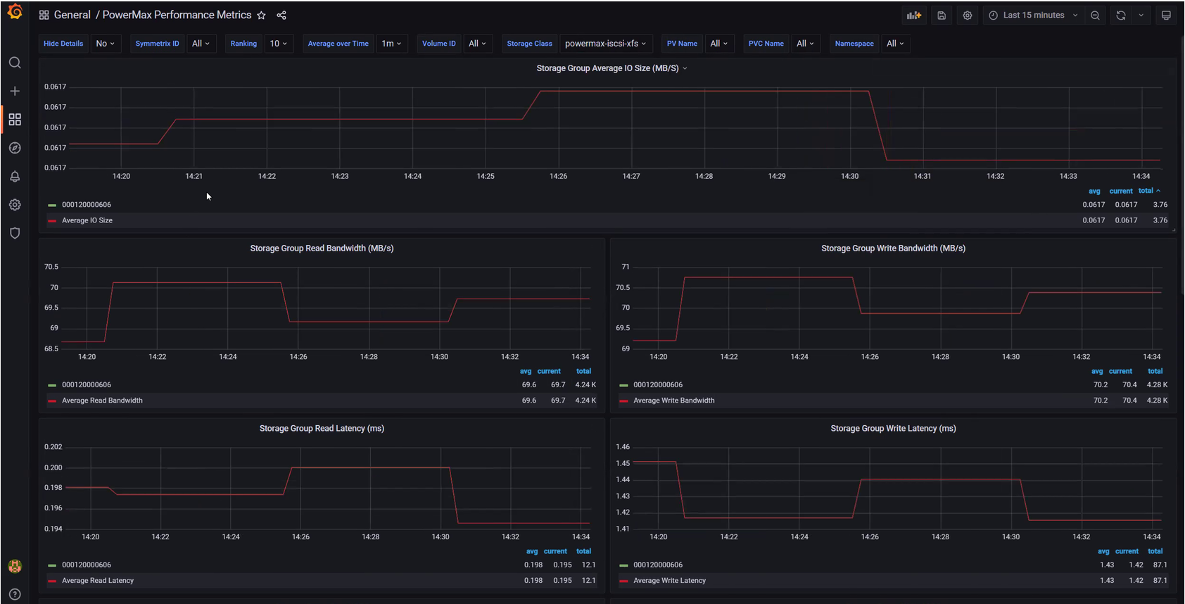
CSM Observability PowerMax support
CSM Observability can collect PowerMax metrics, including the performance of the storage groups that back the PVC, the capacity of the storage resource pool, and more.
Useful links
Stay informed of the latest updates of the Dell CSM eco-system by subscribing to:
- The Dell CSM Github repository
- Our DevOps & Automation Youtube playlist
- The Slack Workspaces at Dell Technologies
- Demo of CSM replication with PowerFlex
Author: Florian Coulombel

CSI drivers 2.0 and Dell EMC Container Storage Modules GA!
Mon, 29 Apr 2024 18:38:49 -0000
|Read Time: 0 minutes
The quarterly update for Dell CSI Driver is here! But today marks a significant milestone because we are also announcing the availability of Dell EMC Container Storage Modules (CSM). Here’s what we’re covering in this blog:
Container Storage Modules
Dell Container Storage Modules is a set of modules that aims to extend Kubernetes storage features beyond what is available in the CSI specification.
The CSM modules will expose storage enterprise features directly within Kubernetes, so developers are empowered to leverage them for their deployment in a seamless way.
Most of these modules are released as sidecar containers that work with the CSI driver for the Dell storage array technology you use.
CSM modules are open-source and freely available from : https://github.com/dell/csm.
Volume Group Snapshot
Many stateful apps can run on top of multiple volumes. For example, we can have a transactional DB like Postgres with a volume for its data and another for the redo log, or Cassandra that is distributed across nodes, each having a volume, and so on.
When you want to take a recoverable snapshot, it is vital to take them consistently at the exact same time.
Dell CSI Volume Group Snapshotter solves that problem for you. With the help of a CustomResourceDefinition, an additional sidecar to the Dell CSI drivers, and leveraging vanilla Kubernetes snapshots, you can manage the life cycle of crash-consistent snapshots. This means you can create a group of volumes for which the drivers create snapshots, restore them, or move them with one shot simultaneously!
To take a crash-consistent snapshot, you can either use labels on your PersistantVolumeClaim, or be explicit and pass the list of PVCs that you want to snap. For example:
apiVersion: v1
apiVersion: volumegroup.storage.dell.com/v1alpha2
kind: DellCsiVolumeGroupSnapshot
metadata:
  # Name must be 13 characters or less in length
  name: "vg-snaprun1"
spec:
  driverName: "csi-vxflexos.dellemc.com"
  memberReclaimPolicy: "Retain"
  volumesnapshotclass: "poweflex-snapclass"
  pvcLabel: "vgs-snap-label"
  # pvcList:
  #   - "pvcName1"
  #   - "pvcName2"
For the first release, CSI for PowerFlex supports Volume Group Snapshot.
Observability
The CSM Observability module is delivered as an open-telemetry agent that collects array-level metrics to scrape them for storage in a Prometheus DB.
The integration is as easy as creating a Prometheus ServiceMonitor for Prometheus. For example:
apiVersion: monitoring.coreos.com/v1
kind: ServiceMonitor
metadata:
  name: otel-collector
  namespace: powerstore
spec:
  endpoints:
  - path: /metrics
    port: exporter-https
    scheme: https
    tlsConfig:
      insecureSkipVerify: true
  selector:
    matchLabels:
      app.kubernetes.io/instance: karavi-observability
      app.kubernetes.io/name: otel-collector
With the observability module, you will gain visibility on the capacity of the volume you manage with Dell CSI drivers and their performance, in terms of bandwidth, IOPS, and response time.
Thanks to pre-canned Grafana dashboards, you will be able to go through these metrics’ history and see the topology between a Kubernetes PersistentVolume (PV) until its translation as a LUN or fileshare in the backend array.
The Kubernetes admin can also collect array level metrics to check the overall capacity performance directly from the familiar Prometheus/Grafana tools.
For the first release, Dell EMC PowerFlex and Dell EMC PowerStore support CSM Observability.
Replication
Each Dell storage array supports replication capabilities. It can be asynchronous with an associated recovery point objective, synchronous replication between sites, or even active-active.
Each replication type serves a different purpose related to the use-case or the constraint you have on your data centers.
The Dell CSM replication module allows creating a persistent volume that can be of any of three replication types -- synchronous, asynchronous, and metro -- assuming the underlying storage box supports it.
The Kubernetes architecture can build on a stretched cluster between two sites or on two or more independent clusters. The module itself is composed of three main components:
- The Replication controller whose role is to manage the CustomResourceDefinition that abstracts the concept of Replication across the Kubernetes cluster
- The Replication sidecar for the CSI driver that will convert the Replication controller request to an actual call on the array side
- The repctl utility, to simplify managing replication objects across multiple Kubernetes clusters
The usual workflow is to create a PVC that is replicated with a classic Kubernetes directive by just picking the right StorageClass. You can then use repctl or edit the DellCSIReplicationGroup CRD to launch operations like Failover, Failback, Reprotect, Suspend, Synchronize, and so on.
For the first release, Dell EMC PowerMax and Dell EMC PowerStore support CSM Replication.
Authorization
With CSM Authorization we are giving back more control of storage consumption to the storage administrator.
The authorization module is an independent service, installed and owned by the storage admin.
Within that module, the storage administrator will create access control policies and storage quotas to make sure that Kubernetes consumers are not overconsuming storage or trying to access data that doesn’t belong to them.
CSM Authorization makes multi-tenant architecture real by enforcing Role-Based Access Control on storage objects coming from multiple and independent Kubernetes clusters.
The authorization module acts as a proxy between the CSI driver and the backend array. Access is granted with an access token that can be revoked at any point in time. Quotas can be changed on the fly to limit or increase storage consumption from the different tenants.
For the first release, Dell EMC PowerMax and Dell EMC PowerFlex support CSM Authorization.
Resilency
When dealing with StatefulApp, if a node goes down, vanilla Kubernetes is pretty conservative.
Indeed, from the Kubernetes control plane, the failing node is seen as not ready. It can be because the node is down, or because of network partitioning between the control plane and the node, or simply because the kubelet is down. In the latter two scenarios, the StatefulApp is still running and possibly writing data on disk. Therefore, Kubernetes won’t take action and lets the admin manually trigger a Pod deletion if desired.
The CSM Resiliency module (sometimes named PodMon) aims to improve that behavior with the help of collected metrics from the array.
Because the driver has access to the storage backend from pretty much all other nodes, we can see the volume status (mapped or not) and its activity (are there IOPS or not). So when a node goes into NotReady state, and we see no IOPS on the volume, Resiliency will relocate the Pod to a new node and clean whatever leftover objects might exist.
The entire process happens in seconds between the moment a node is seen down and the rescheduling of the Pod.
To protect an app with the resiliency module, you only have to add the label podmon.dellemc.com/driver to it, and it is then protected.
For more details on the module’s design, you can check the documentation here.
For the first release, Dell EMC PowerFlex and Dell EMC Unity support CSM Resiliency.
Installer
Each module above is released either as an independent helm chart or as an option within the CSI Drivers.
For more complex deployments, which may involve multiple Kubernetes clusters or a mix of modules, it is possible to use the csm installer.
The CSM Installer, built on top of carvel gives the user a single command line to create their CSM-CSI application and to manage them outside the Kubernetes cluster.
For the first release, all drivers and modules support the CSM Installer.
New CSI features
Across portfolio
For each driver, this release provides:
- Support of OpenShift 4.8
- Support of Kubernetes 1.22
- Support of Rancher Kubernetes Engine 2
- Normalized configurations between drivers
- Dynamic Logging Configuration
- New CSM installer
VMware Tanzu Kubernetes Grid
VMware Tanzu offers storage management by means of its CNS-CSI driver, but it doesn’t support ReadWriteMany access mode.
If your workload needs concurrent access to the filesystem, you can now rely on CSI Driver for PowerStore, PowerScale and Unity through the NFS protocol. The three platforms are officially supported and qualified on Tanzu.
NFS behind NAT
NFS Driver, PowerStore, PowerScale, and Unity have all been tested and work when the Kubernetes cluster is behind a private network.
PowerScale
By default, the CSI driver creates volumes with 777 POSIX permission on the directory.
Now with the isiVolumePathPermissions parameter, you can use ACLs or any more permissive POSIX rights.
The isiVolumePathPermissions can be configured as part of the ConfigMap with the PowerScale settings or at the StorageClass level. The accepted parameter values are: private_read, private, public_read, public_read_write, and public for the ACL or any combination of [POSIX Mode].
Useful links
For more details you can:
- Watch CSM demos on our VP Youtube channel : https://www.youtube.com/user/itzikreich/
- Ask for help from the Dell container community website
- Subscribe to Github notification and be informed of the latest releases on: https://github.com/dell/csm
- Chat with us on Slack
Author: Florian Coulombel

Looking Ahead: Dell Container Storage Modules 1.2
Mon, 29 Apr 2024 18:36:49 -0000
|Read Time: 0 minutes
The quarterly update for Dell CSI Drivers & Dell Container Storage Modules (CSM) is here! Here’s what we’re planning.
CSM Features
New CSM Operator!
Dell Container Storage Modules (CSM) add data services and features that are not in the scope of the CSI specification today. The new CSM Operator simplifies the deployment of CSMs. With an ever-growing ecosystem and added features, deploying a driver and its affiliated modules need to be carefully studied before beginning the deployment.
The new CSM Operator:
- Serves as a one-stop-shop for deploying all Dell CSI driver and Container Storage Modules
- Simplifies the install and upgrade operations
- Leverages the Operator framework to give a clear status of the deployment of the resources
- Is certified by Red Hat OpenShift
In the short/middle term, the CSM Operator will deprecate the experimental CSM Installer.
Replication support with PowerScale
For disaster recovery protection, PowerScale implements data replication between appliances by means of the the SyncIQ feature. SyncIQ replicates the data between two sites, where one is read-write while the other is read-only, similar to Dell storage backends with async or sync replication.
The role of the CSM replication module and underlying CSI driver is to provision the volume within Kubernetes clusters and prepare the export configurations, quotas, and so on.
CSM Replication for PowerScale has been designed and implemented in such a way that it won’t collide with your existing Superna Eyeglass DR utility.
A live-action demo will be posted in the coming weeks on our VP YouTube channel: https://www.youtube.com/user/itzikreich/.
CSI features
Across the portfolio
In this release, each CSI driver:
- Supports OpenShift 4.9
- Supports Kubernetes 1.23
- Supports the CSI Spec 1.5
- Updates the latest UBI-minimal image
- Supports fsGroupPolicy
fsGroupPolicy support
Kubernetes v1.19 introduced the fsGroupPolicy to give more control to the CSI driver over the permission sets in the securityContext.
There are three possible options:
- None -- which means that the fsGroup directive from the securityContext will be ignored
- File -- which means that the fsGroup directive will be applied on the volume. This is the default setting for NAS systems such as PowerScale or Unity-File.
- ReadWriteOnceWithFSType -- which means that the fsGroup directive will be applied on the volume if it has fsType defined and is ReadWriteOnce. This is the default setting for block systems such as PowerMax and PowerStore-Block.
In all cases, Dell CSI drivers let kubelet perform the change ownership operations and do not do it at the driver level.
Standalone Helm install
Drivers for PowerFlex and Unity can now be installed with the help of the install scripts we provide under the dell-csi-installer directory.
A standalone Helm chart helps to easily integrate the driver installation with the agent for Continuous Deployment like Flux or Argo CD.
Note: To ensure that you install the driver on a supported Kubernetes version, the Helm charts take advantage of the kubeVersion field. Some Kubernetes distributions use labels in kubectl version (such as v1.21.3-mirantis-1 and v1.20.7-eks-1-20-7) that require manual editing.
Volume Health Monitoring support
Drivers for PowerFlex and Unity implement Volume Health Monitoring.
This feature is currently in alpha in Kubernetes (in Q1-2022), and is disabled with a default installation.
Once enabled, the drivers will expose the standard storage metrics, such as capacity usage and inode usage through the Kubernetes /metrics endpoint. The metrics will flow natively in popular dashboards like the ones built-in OpenShift Monitoring:
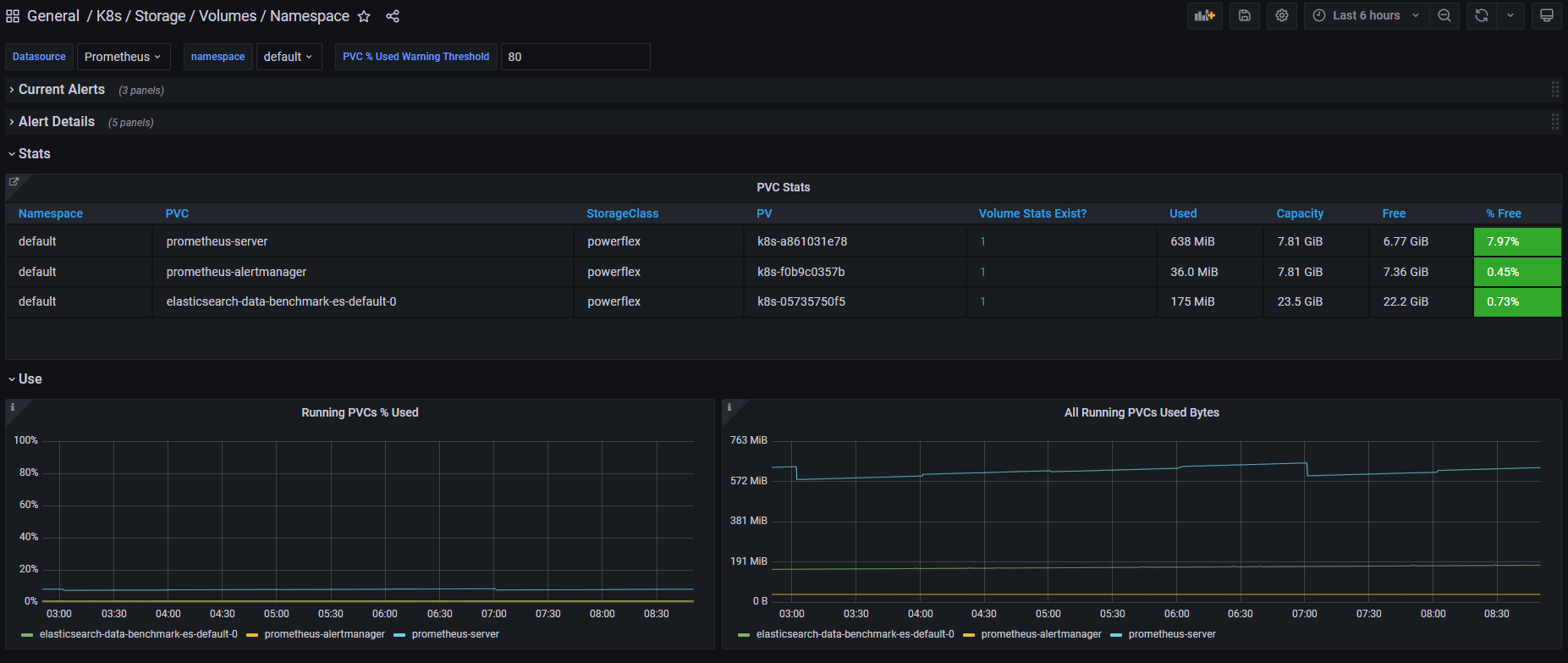
Pave the way for full open source!
All Dell drivers and dependencies like gopowerstore, gobrick, and more are now on Github and will be fully open-sourced. The umbrella project is and remains https://github.com/dell/csm, from which you can open tickets and see the roadmap.
Google Anthos 1.9
The Dell partnership with Google continues, and the latest CSI drivers for PowerScale and PowerStore support Anthos v1.9.
NFSv4 POSIX and ACL support
Both CSI PowerScale and PowerStore now allow setting the default permissions for the newly created volume. To do this, you can use POSIX octal notation or ACL.
- In PowerScale, you can use plain ACL or built-in values such as private_read, private, public_read, public_read_write, public or custom ones;
- In PowerStore, you can use the custom ones such as A::OWNER@:RWX, A::GROUP@:RWX, and A::OWNER@:rxtncy.
Useful links
For more details you can:
- Watch these great CSM demos on our VP YouTube channel: https://www.youtube.com/user/itzikreich/
- Subscribe to Github notification and be informed of the latest releases on: https://github.com/dell/csm
- Ask for help or chat with us on Slack
Author: Florian Coulombel

How to Build a Custom Dell CSI Driver
Mon, 29 Apr 2024 18:15:25 -0000
|Read Time: 0 minutes
With all the Dell Container Storage Interface (CSI) drivers and dependencies being open-source, anyone can tweak them to fit a specific use case.
This blog shows how to create a patched version of a Dell CSI Driver for PowerScale.
The premise
As a practical example, the following steps show how to create a patched version of Dell CSI Driver for PowerScale that supports a longer mounted path.
The CSI Specification defines that a driver must accept a max path of 128 bytes minimal:
// SP SHOULD support the maximum path length allowed by the operating
// system/filesystem, but, at a minimum, SP MUST accept a max path
// length of at least 128 bytes.
Dell drivers use the gocsi library as a common boilerplate for CSI development. That library enforces the 128 bytes maximum path length.
The PowerScale hardware supports path lengths up to 1023 characters, as described in the File system guidelines chapter of the PowerScale spec. We’ll therefore build a csi-powerscale driver that supports that maximum length path value.
Steps to patch a driver
Dependencies
The Dell CSI drivers are all built with golang and, obviously, run as a container. As a result, the prerequisites are relatively simple. You need:
- Golang (v1.16 minimal at the time of the publication of that post)
- Podman or Docker
- And optionally make to run our Makefile
Clone, branch, and patch
The first thing to do is to clone the official csi-powerscale repository in your GOPATH source directory.
cd $GOPATH/src/github.com/
git clone git@github.com:dell/csi-powerscale.git dell/csi-powerscale
cd dell/csi-powerscale
You can then pick the version of the driver you want to patch; git tag gives the list of versions.
In this example, we pick the v2.1.0 with git checkout v2.1.0 -b v2.1.0-longer-path.
The next step is to obtain the library we want to patch.
gocsi and every other open-source component maintained for Dell CSI are available on https://github.com/dell.
The following figure shows how to fork the repository on your private github:
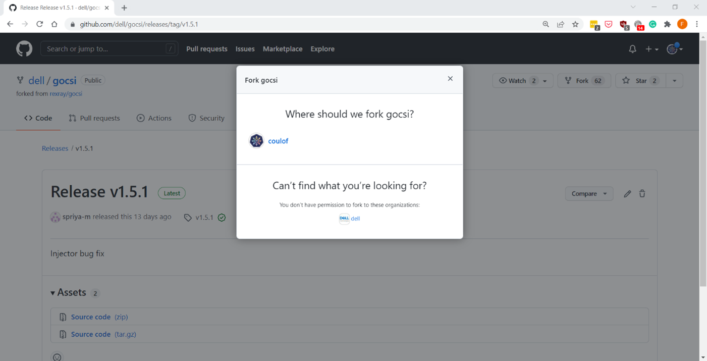
Now we can get the library with:
cd $GOPATH/src/github.com/
git clone git@github.com:coulof/gocsi.git coulof/gocsi
cd coulof/gocsi
To simplify the maintenance and merge of future commits, it is wise to add the original repo as an upstream branch with:
git remote add upstream git@github.com:dell/gocsi.gitThe next important step is to pick and choose the correct library version used by our version of the driver.
We can check the csi-powerscale dependency file with: grep gocsi $GOPATH/src/github.com/dell/csi-powerscale/go.mod and create a branch of that version. In this case, the version is v1.5.0, and we can branch it with: git checkout v1.5.0 -b v1.5.0-longer-path.
Now it’s time to hack our patch! Which is… just a oneliner:
--- a/middleware/specvalidator/spec_validator.go
+++ b/middleware/specvalidator/spec_validator.go
@@ -770,7 +770,7 @@ func validateVolumeCapabilitiesArg(
 }

 const (
-       maxFieldString = 128
+       maxFieldString = 1023
        maxFieldMap    = 4096
        maxFieldNodeId = 256
 )
We can then commit and push our patched library with a nice tag:
git commit -a -m 'increase path limit'
git push --set-upstream origin v1.5.0-longer-path
git tag -a v1.5.0-longer-path
git push --tags
Build
With the patch committed and pushed, it’s time to build the CSI driver binary and its container image.
Let’s go back to the csi-powerscale main repo: cd $GOPATH/src/github.com/dell/csi-powerscale
As mentioned in the introduction, we can take advantage of the replace directive in the go.mod file to point to the patched lib. In this case we add the following:
diff --git a/go.mod b/go.mod
index 5c274b4..c4c8556 100644
--- a/go.mod
+++ b/go.mod
@@ -26,6 +26,7 @@ require (
 )

 replace (
+       github.com/dell/gocsi => github.com/coulof/gocsi v1.5.0-longer-path
        k8s.io/api => k8s.io/api v0.20.2
        k8s.io/apiextensions-apiserver => k8s.io/apiextensions-apiserver v0.20.2
        k8s.io/apimachinery => k8s.io/apimachinery v0.20.2
When that is done, we obtain the new module from the online repo with: go mod download
Note: If you want to test the changes locally only, we can use the replace directive to point to the local directory with:
replace github.com/dell/gocsi => ../../coulof/gocsiWe can then build our new driver binary locally with: make build
After compiling it successfully, we can create the image. The shortest path to do that is to replace the csi-isilon binary from the dellemc/csi-isilon docker image with:
cat << EOF > Dockerfile.patch
FROM dellemc/csi-isilon:v2.1.0
COPY "csi-isilon" .
EOF


docker build -t coulof/csi-isilon:v2.1.0-long-path -f Dockerfile.patch .
Alternatively, you can rebuild an entire docker image using provided Makefile.
By default, the driver uses a Red Hat Universal Base Image minimal. That base image sometimes misses dependencies, so you can use another flavor, such as:
BASEIMAGE=registry.fedoraproject.org/fedora-minimal:latest REGISTRY=docker.io IMAGENAME=coulof/csi-powerscale IMAGETAG=v2.1.0-long-path make podman-buildThe image is ready to be pushed in whatever image registry you prefer. In this case, this is hub.docker.com: docker push coulof/csi-isilon:v2.1.0-long-path.
Update CSI Kubernetes deployment
The last step is to replace the driver image used in your Kubernetes with your custom one.
Again, multiple solutions are possible, and the one to choose depends on how you deployed the driver.
If you used the helm installer, you can add the following block at the top of the myvalues.yaml file:
images:
  driver: docker.io/coulof/csi-powerscale:v2.1.0-long-path
Then update or uninstall/reinstall the driver as described in the documentation.
If you decided to use the Dell CSI Operator, you can simply point to the new image:
apiVersion: storage.dell.com/v1
kind: CSIIsilon
metadata:
  name: isilon
spec:
  driver:
    common:
      image: "docker.io/coulof/csi-powerscale:v2.1.0-long-path"
...
Or, if you want to do a quick and dirty test, you can create a patch file (here named path_csi-isilon_controller_image.yaml) with the following content:
spec:
  template:
    spec:
      containers:
      - name: driver
        image: docker.io/coulof/csi-powerscale:v2.1.0-long-path
You can then apply it to your existing install with: kubectl patch deployment -n powerscale isilon-controller --patch-file path_csi-isilon_controller_image.yaml
In all cases, you can check that everything works by first making sure that the Pod is started:
kubectl get pods -n powerscale and that the logs are clean:
kubectl logs -n powerscale -l app=isilon-controller -c driver.Wrap-up and disclaimer
As demonstrated, thanks to the open source, it’s easy to fix and improve Dell CSI drivers or Dell Container Storage Modules.
Keep in mind that Dell officially supports (through tickets, Service Requests, and so on) the image and binary, but not the custom build.
Thanks for reading and stay tuned for future posts on Dell Storage and Kubernetes!
Author: Florian Coulombel

Looking Ahead: Dell Container Storage Modules 1.2
Mon, 29 Apr 2024 18:11:07 -0000
|Read Time: 0 minutes
The quarterly update for Dell CSI Drivers & Dell Container Storage Modules (CSM) is here! Here’s what we’re planning.
CSM Features
New CSM Operator!
Dell Container Storage Modules (CSM) add data services and features that are not in the scope of the CSI specification today. The new CSM Operator simplifies the deployment of CSMs. With an ever-growing ecosystem and added features, deploying a driver and its affiliated modules need to be carefully studied before beginning the deployment.
The new CSM Operator:
- Serves as a one-stop-shop for deploying all Dell CSI driver and Container Storage Modules
- Simplifies the install and upgrade operations
- Leverages the Operator framework to give a clear status of the deployment of the resources
- Is certified by Red Hat OpenShift
In the short/middle term, the CSM Operator will deprecate the experimental CSM Installer.
Replication support with PowerScale
For disaster recovery protection, PowerScale implements data replication between appliances by means of the the SyncIQ feature. SyncIQ replicates the data between two sites, where one is read-write while the other is read-only, similar to Dell storage backends with async or sync replication.
The role of the CSM replication module and underlying CSI driver is to provision the volume within Kubernetes clusters and prepare the export configurations, quotas, and so on.
CSM Replication for PowerScale has been designed and implemented in such a way that it won’t collide with your existing Superna Eyeglass DR utility.
A live-action demo will be posted in the coming weeks on our VP YouTube channel: https://www.youtube.com/user/itzikreich/.
CSI features
Across the portfolio
In this release, each CSI driver:
- Supports OpenShift 4.9
- Supports Kubernetes 1.23
- Supports the CSI Spec 1.5
- Updates the latest UBI-minimal image
- Supports fsGroupPolicy
fsGroupPolicy support
Kubernetes v1.19 introduced the fsGroupPolicy to give more control to the CSI driver over the permission sets in the securityContext.
There are three possible options:
- None -- which means that the fsGroup directive from the securityContext will be ignored
- File -- which means that the fsGroup directive will be applied on the volume. This is the default setting for NAS systems such as PowerScale or Unity-File.
- ReadWriteOnceWithFSType -- which means that the fsGroup directive will be applied on the volume if it has fsType defined and is ReadWriteOnce. This is the default setting for block systems such as PowerMax and PowerStore-Block.
In all cases, Dell CSI drivers let kubelet perform the change ownership operations and do not do it at the driver level.
Standalone Helm install
Drivers for PowerFlex and Unity can now be installed with the help of the install scripts we provide under the dell-csi-installer directory.
A standalone Helm chart helps to easily integrate the driver installation with the agent for Continuous Deployment like Flux or Argo CD.
Note: To ensure that you install the driver on a supported Kubernetes version, the Helm charts take advantage of the kubeVersion field. Some Kubernetes distributions use labels in kubectl version (such as v1.21.3-mirantis-1 and v1.20.7-eks-1-20-7) that require manual editing.
Volume Health Monitoring support
Drivers for PowerFlex and Unity implement Volume Health Monitoring.
This feature is currently in alpha in Kubernetes (in Q1-2022), and is disabled with a default installation.
Once enabled, the drivers will expose the standard storage metrics, such as capacity usage and inode usage through the Kubernetes /metrics endpoint. The metrics will flow natively in popular dashboards like the ones built-in OpenShift Monitoring:
Pave the way for full open source!
All Dell drivers and dependencies like gopowerstore, gobrick, and more are now on Github and will be fully open-sourced. The umbrella project is and remains https://github.com/dell/csm, from which you can open tickets and see the roadmap.
Google Anthos 1.9
The Dell partnership with Google continues, and the latest CSI drivers for PowerScale and PowerStore support Anthos v1.9.
NFSv4 POSIX and ACL support
Both CSI PowerScale and PowerStore now allow setting the default permissions for the newly created volume. To do this, you can use POSIX octal notation or ACL.
- In PowerScale, you can use plain ACL or built-in values such as private_read, private, public_read, public_read_write, public or custom ones;
- In PowerStore, you can use the custom ones such as A::OWNER@:RWX, A::GROUP@:RWX, and A::OWNER@:rxtncy.
Useful links
For more details you can:
- Watch these great CSM demos on our VP YouTube channel: https://www.youtube.com/user/itzikreich/
- Subscribe to Github notification and be informed of the latest releases on: https://github.com/dell/csm
- Ask for help or chat with us on Slack
Author: Florian Coulombel

CSI drivers 2.0 and Dell EMC Container Storage Modules GA!
Mon, 29 Apr 2024 17:44:07 -0000
|Read Time: 0 minutes
The quarterly update for Dell CSI Driver is here! But today marks a significant milestone because we are also announcing the availability of Dell EMC Container Storage Modules (CSM). Here’s what we’re covering in this blog:
Container Storage Modules
Dell Container Storage Modules is a set of modules that aims to extend Kubernetes storage features beyond what is available in the CSI specification.
The CSM modules will expose storage enterprise features directly within Kubernetes, so developers are empowered to leverage them for their deployment in a seamless way.
Most of these modules are released as sidecar containers that work with the CSI driver for the Dell storage array technology you use.
CSM modules are open-source and freely available from : https://github.com/dell/csm.
Volume Group Snapshot
Many stateful apps can run on top of multiple volumes. For example, we can have a transactional DB like Postgres with a volume for its data and another for the redo log, or Cassandra that is distributed across nodes, each having a volume, and so on.
When you want to take a recoverable snapshot, it is vital to take them consistently at the exact same time.
Dell CSI Volume Group Snapshotter solves that problem for you. With the help of a CustomResourceDefinition, an additional sidecar to the Dell CSI drivers, and leveraging vanilla Kubernetes snapshots, you can manage the life cycle of crash-consistent snapshots. This means you can create a group of volumes for which the drivers create snapshots, restore them, or move them with one shot simultaneously!
To take a crash-consistent snapshot, you can either use labels on your PersistantVolumeClaim, or be explicit and pass the list of PVCs that you want to snap. For example:
apiVersion: v1
apiVersion: volumegroup.storage.dell.com/v1alpha2
kind: DellCsiVolumeGroupSnapshot
metadata:
  # Name must be 13 characters or less in length
  name: "vg-snaprun1"
spec:
  driverName: "csi-vxflexos.dellemc.com"
  memberReclaimPolicy: "Retain"
  volumesnapshotclass: "poweflex-snapclass"
  pvcLabel: "vgs-snap-label"
  # pvcList:
  #   - "pvcName1"
  #   - "pvcName2"
For the first release, CSI for PowerFlex supports Volume Group Snapshot.
Observability
The CSM Observability module is delivered as an open-telemetry agent that collects array-level metrics to scrape them for storage in a Prometheus DB.
The integration is as easy as creating a Prometheus ServiceMonitor for Prometheus. For example:
apiVersion: monitoring.coreos.com/v1
kind: ServiceMonitor
metadata:
  name: otel-collector
  namespace: powerstore
spec:
  endpoints:
  - path: /metrics
    port: exporter-https
    scheme: https
    tlsConfig:
      insecureSkipVerify: true
  selector:
    matchLabels:
      app.kubernetes.io/instance: karavi-observability
      app.kubernetes.io/name: otel-collector
With the observability module, you will gain visibility on the capacity of the volume you manage with Dell CSI drivers and their performance, in terms of bandwidth, IOPS, and response time.
Thanks to pre-canned Grafana dashboards, you will be able to go through these metrics’ history and see the topology between a Kubernetes PersistentVolume (PV) until its translation as a LUN or fileshare in the backend array.
The Kubernetes admin can also collect array level metrics to check the overall capacity performance directly from the familiar Prometheus/Grafana tools.
For the first release, Dell EMC PowerFlex and Dell EMC PowerStore support CSM Observability.
Replication
Each Dell storage array supports replication capabilities. It can be asynchronous with an associated recovery point objective, synchronous replication between sites, or even active-active.
Each replication type serves a different purpose related to the use-case or the constraint you have on your data centers.
The Dell CSM replication module allows creating a persistent volume that can be of any of three replication types -- synchronous, asynchronous, and metro -- assuming the underlying storage box supports it.
The Kubernetes architecture can build on a stretched cluster between two sites or on two or more independent clusters. The module itself is composed of three main components:
- The Replication controller whose role is to manage the CustomResourceDefinition that abstracts the concept of Replication across the Kubernetes cluster
- The Replication sidecar for the CSI driver that will convert the Replication controller request to an actual call on the array side
- The repctl utility, to simplify managing replication objects across multiple Kubernetes clusters
The usual workflow is to create a PVC that is replicated with a classic Kubernetes directive by just picking the right StorageClass. You can then use repctl or edit the DellCSIReplicationGroup CRD to launch operations like Failover, Failback, Reprotect, Suspend, Synchronize, and so on.
For the first release, Dell EMC PowerMax and Dell EMC PowerStore support CSM Replication.
Authorization
With CSM Authorization we are giving back more control of storage consumption to the storage administrator.
The authorization module is an independent service, installed and owned by the storage admin.
Within that module, the storage administrator will create access control policies and storage quotas to make sure that Kubernetes consumers are not overconsuming storage or trying to access data that doesn’t belong to them.
CSM Authorization makes multi-tenant architecture real by enforcing Role-Based Access Control on storage objects coming from multiple and independent Kubernetes clusters.
The authorization module acts as a proxy between the CSI driver and the backend array. Access is granted with an access token that can be revoked at any point in time. Quotas can be changed on the fly to limit or increase storage consumption from the different tenants.
For the first release, Dell EMC PowerMax and Dell EMC PowerFlex support CSM Authorization.
Resilency
When dealing with StatefulApp, if a node goes down, vanilla Kubernetes is pretty conservative.
Indeed, from the Kubernetes control plane, the failing node is seen as not ready. It can be because the node is down, or because of network partitioning between the control plane and the node, or simply because the kubelet is down. In the latter two scenarios, the StatefulApp is still running and possibly writing data on disk. Therefore, Kubernetes won’t take action and lets the admin manually trigger a Pod deletion if desired.
The CSM Resiliency module (sometimes named PodMon) aims to improve that behavior with the help of collected metrics from the array.
Because the driver has access to the storage backend from pretty much all other nodes, we can see the volume status (mapped or not) and its activity (are there IOPS or not). So when a node goes into NotReady state, and we see no IOPS on the volume, Resiliency will relocate the Pod to a new node and clean whatever leftover objects might exist.
The entire process happens in seconds between the moment a node is seen down and the rescheduling of the Pod.
To protect an app with the resiliency module, you only have to add the label podmon.dellemc.com/driver to it, and it is then protected.
For more details on the module’s design, you can check the documentation here.
For the first release, Dell EMC PowerFlex and Dell EMC Unity support CSM Resiliency.
Installer
Each module above is released either as an independent helm chart or as an option within the CSI Drivers.
For more complex deployments, which may involve multiple Kubernetes clusters or a mix of modules, it is possible to use the csm installer.
The CSM Installer, built on top of carvel gives the user a single command line to create their CSM-CSI application and to manage them outside the Kubernetes cluster.
For the first release, all drivers and modules support the CSM Installer.
New CSI features
Across portfolio
For each driver, this release provides:
- Support of OpenShift 4.8
- Support of Kubernetes 1.22
- Support of Rancher Kubernetes Engine 2
- Normalized configurations between drivers
- Dynamic Logging Configuration
- New CSM installer
VMware Tanzu Kubernetes Grid
VMware Tanzu offers storage management by means of its CNS-CSI driver, but it doesn’t support ReadWriteMany access mode.
If your workload needs concurrent access to the filesystem, you can now rely on CSI Driver for PowerStore, PowerScale and Unity through the NFS protocol. The three platforms are officially supported and qualified on Tanzu.
NFS behind NAT
NFS Driver, PowerStore, PowerScale, and Unity have all been tested and work when the Kubernetes cluster is behind a private network.
PowerScale
By default, the CSI driver creates volumes with 777 POSIX permission on the directory.
Now with the isiVolumePathPermissions parameter, you can use ACLs or any more permissive POSIX rights.
The isiVolumePathPermissions can be configured as part of the ConfigMap with the PowerScale settings or at the StorageClass level. The accepted parameter values are: private_read, private, public_read, public_read_write, and public for the ACL or any combination of [POSIX Mode].
Useful links
For more details you can:
- Watch CSM demos on our VP Youtube channel : https://www.youtube.com/user/itzikreich/
- Ask for help from the Dell container community website
- Subscribe to Github notification and be informed of the latest releases on: https://github.com/dell/csm
- Chat with us on Slack
Author: Florian Coulombel

Kubernetes Node Non-Graceful Shutdown and Remediation: Insights from Dell Technologies
Tue, 12 Dec 2023 18:16:57 -0000
|Read Time: 0 minutes
Introduction
Kubernetes has become a pivotal technology in managing containerized applications, but it's not without its challenges, particularly when dealing with Stateful Apps and non-graceful shutdown scenarios. This article delves into the intricacies of handling such situations, drawing insights from Dell Technologies' expertise and more importantly, how to enable it.
Understanding Graceful vs. Non-Graceful Node Shutdowns in Kubernetes
A 'graceful' node shutdown in Kubernetes is an orchestrated process. When kubelet detects a node shutdown event, it terminates the pods on that node properly, releasing resources before the actual shutdown. This orderly process allows critical pods to be terminated after regular pods, ensuring an application continues operating as long as possible. This process is vital for maintaining high availability and resilience in applications.
However, issues arise with a non-graceful shutdown, like a hard stop or node crash. In such cases, kubelet fails to detect a clean shutdown event. This leads to Kubernetes marking the node ‘NotReady', and Pods in a Stateful Set can remain stuck in 'Terminating' mode indefinitely!
Kubernetes adopts a cautious approach in these scenarios since it cannot ascertain if the issue is a total node failure, a kubelet problem, or a network glitch. This distinction is critical, especially for stateful apps, where rescheduling amidst active data writing could lead to severe data corruption.
Role of Dell's Container Storage Module (CSM) for Resiliency
Dell's CSM for Resiliency plays a crucial role in automating decision-making in these complex scenarios, aiming to minimize manual intervention and maximize uptime. The module's functionality is highlighted through a typical workflow:
- Consider a pod with two mounted volumes, annotated for protection with CSM resiliency.
- Upon an abrupt node power-off, the Kubernetes API detects the failure, marking the node as 'Not Ready'.
- The podmon controller of CSM Resiliency then interrogates the storage array, querying its status regarding the node and volumes.
- Depending on its findings and a set heuristic, the module determines whether it's safe to reschedule the pod.
- If rescheduling is deemed safe, the module quickly fences off access for the failed node, removes the volume attachment, and force-deletes the pod, enabling Kubernetes to reschedule it efficiently.
The following tutorial allow to test the functionality live: https://dell.github.io/csm-docs/docs/interactive-tutorials/
How to enable the module ?
To take advantage of the CSM resiliency you need two things:
- Enable it for your driver, for example with PowerFlex
- With the CSM wizard, just check the resiliency box
- With the Operator just set enable: true in the section .spec.modules.name['resiliency']
- With the helm chart set enable: true in the section .csi-vxflexos.podmon
- Then protect you application by adding the magic label podmon.dellemc.com/driver: csi-vxflexos
Conclusion:
Managing non-graceful shutdowns in Kubernetes, particularly for stateful applications, is a complex but essential aspect of ensuring system resilience and data integrity.
Tools like Dell's CSM for Resiliency are instrumental in navigating these challenges, offering automated, intelligent solutions that keep applications running smoothly even in the face of unexpected failures.
Sources
Stay informed of the latest updates of Dell CSM eco-system by subscribing to:
* The Dell CSM Github repository
* Our DevOps & Automation Youtube playlist
* The Slack

Kubernetes on Z with PowerMax: Modern Software Running on Mainframe

Mon, 02 Oct 2023 13:21:45 -0000
|Read Time: 0 minutes
Benefits of Kubernetes on System Z and LinuxOne
When I was a customer, I consistently evaluated how to grow the technical influence of the mainframe platform. If I were talking about the financials of the platform, I would evaluate the total cost of ownership (TCO) alongside various IT solutions and the value deduced thereof. If discussing existing technical pain points, I would evaluate technical solutions that may alleviate the issue.
For example, when challenged with finding a solution for a client organization aiming to refresh various x86 servers, I searched online presentations, YouTube videos, and technical websites for a spark. The client organization had already identified the pain point. The hard part was how.
Over time, I found the ability to run Linux on a mainframe (called Linux on Z), using an Integrated Facility for Linux (IFL) engine. Once the idea was formed, I started baking the cake. I created a proof-of-concept environment installing Linux and a couple of applications and began testing.
The light-bulb moment came not in resolving the original pain point, but in discovering new opportunities I had not originally thought of. More specifically:
- Physical server consolidation – I’ll create a plethora of virtual servers when needed
- License Consolidation – Certain applications with x86 were licensed on a per engine basis. A quad core x86 server may need four application licenses to function. I needed one license for my Linux on Z environment (at the time of testing)
- Scalability – I could scale horizontally by adding more virtual machines and vertically by increasing the network ports accessible to the server and adding more memory/storage
- Reliability – Mainframe technology has been known to be reliable, utilizing fault tolerant mechanisms within the software and hardware to continue business operations
With the 2023 addition of Kubernetes on LinuxOne (mainframe that only runs Linux), you can scale, reduce TCO, and build that hybrid cloud your IT management requires. With Kubernetes providing container orchestration irrelevant of the underlying hardware and architecture, you can leverage the benefits of LinuxOne to deploy your applications in a structured fashion.
Benefits when deploying Kubernetes to Linux on Z may include:
- Enablement of DevOps processes
- Container Scalability – using one LinuxOne box with hundreds (if not thousands) of containers
- Hybrid Cloud Strategy – where LinuxOne is servicing various internal business organizations with their compute and storage needs
With Dell providing storage to mainframe environments with PowerMax 8500/2500, a Container Storage Interface (CSI) was created to simplify your experience with allocating storage to Kubernetes environments when using Linux on Z with Kubernetes.
The remaining content will focus on the CSI for PowerMax. Continue reading to explore what’s possible.
Deploy Kubernetes
Linux on IBM Z runs on s390x architecture. This means that all the software we use needs to be compiled with that architecture in mind.
Luckily, Kubernetes, CSI sidecars, and Dell CSI drivers are built in Golang. Since the early days of Go, the portability and support of different OS and architectures has been one of the goals of the project. You can get the list of compatible OS and architecture with your go version using the command:
go tool dist listThe easiest and most straightforward way of trying Kubernetes on LinuxOne is by using the k3s distro. It installs with the following one-liner:
curl -sfL https://get.k3s.io | sh -
Build Dell CSI driver
The Dell CSI Driver for PowerMax is composed of a container to run all actions against Unisphere and mount a LUN to a pod, with a set of official CSI sidecars to interact with Kubernetes calls.
The Kubernetes official sidecars are published for multiple architectures including s390x while Dell publishes only images for x86_64.
To build the driver, we will first build the binary and then the image.
Binary
First, let’s clone the driver from https://github.com/dell/csi-powermax in your GOPATH. To build the driver, go in the directory and just execute:
CGO_ENABLED=0 GOOS=linux GOARCH=s390x GO111MODULE=on go buildAt the end of the build, you must have a single binary with static libs compiled for the s390x:
file csi-powermax
csi-powermax: ELF 64-bit MSB executable, IBM S/390, version 1 (SYSV), statically linked, Go BuildID=…, with debug_info, not stripped
Container
The distributed driver uses minimal Red Hat Universal Base Image. There is no s390x compatible UBI image. Therefore, we need to rebuild the container image from a Fedora base-image.
The following is the Dockerfile:
# Dockerfile to build PowerMax CSI Driver
FROM docker.io/fedora:37

# dependencies, following by cleaning the cache
RUN yum install -y \
     util-linux \
     e2fsprogs \
     which \
     xfsprogs \
     device-mapper-multipath \
     && \
     yum clean all \
     && \
     rm -rf /var/cache/run

# validate some cli utilities are found
RUN which mkfs.ext4
RUN which mkfs.xfs

COPY "csi-powermax" .
COPY "csi-powermax.sh" .
ENTRYPOINT ["/csi-powermax.sh"]
We can now build our container image with the help of docker buildx, which makes building cross-architecture a breeze:
docker buildx build -o type=registry -t coulof/csi-powermax:v2.8.0 --platform=linux/s390x -f Dockerfile.s390x .The last step is to change the image in the helm chart to point to the new one: https://github.com/dell/helm-charts/blob/main/charts/csi-powermax/values.yaml
Et voilà! Everything else is the same as with a regular CSI driver.
Wrap-up, limitations, and disclaimer
Thanks to the open-source model of Kubernetes and Dell CSM, it’s easy to build and utilize them for many different architectures.
The CSI driver for PowerMax supports FBA devices via Fiber Channel and iSCSI. There is no support for CKD devices which require code changes.
The CSI driver for PowerMax allows CSI-compliant calls.
Note: Dell officially supports (through Github tickets, Service Requests, and Slack) the image and binary, but not the custom build.
Useful links
Stay informed of the latest updates of the Dell CSM eco-system by subscribing to:
Authors: Justin Bastin & Florian Coulombel

CSM 1.8 Release is Here!
Fri, 22 Sep 2023 21:29:12 -0000
|Read Time: 0 minutes
Introduction
This is already the third release of Dell Container Storage Modules (CSM)!
The official changelog is available in the CHANGELOG directory of the CSM repository.
CSI Features
Supported Kubernetes distributions
The newly supported Kubernetes distributions are :
- Kubernetes 1.28
- OpenShift 4.13
SD-NAS support for PowerMax and PowerFlex
Historically, PowerMax and PowerFlex are Dell’s high-end and SDS for block storage. Both of these backends recently introduced support for software defined NAS.
This means that the respective CSI drivers can now provision PVC with the ReadWriteMany access mode for the volume type file. In other words, thanks to the NFS protocol different nodes from the Kubernetes cluster can access the same volume concurrently. This feature is particularly useful for applications, such as log management tools like Splunk or Elastic Search, that need to process logs coming from multiple Pods.
CSI Specification compliance
Storage capacity tracking
Like PowerScale in v1.7.0, PowerMax and Dell Unity allow you to check the storage capacity on a node before deploying storage to that node. This isn't that relevant in the case of shared storage, because shared storage generally will always show the same capacity to each node in the cluster. However, it could prove useful if the array lacks available storage.
Using this feature, an object from the CSIStorageCapacity type is created by the CSI driver in the same namespace as the CSI driver, one for each storageClass.
An example:
kubectl get csistoragecapacities -n unity # This shows one object per storageClass.
Volume Limits
The Volume Limits feature is added to both PowerStore and PowerFlex. All Dell storage platforms now implement this feature.
This option limits the maximum number of volumes to which a Kubernetes worker node can connect. This can be configured on a per-node basis, or cluster-wide. Setting this variable to zero disables the limit.
Here are some PowerStore examples.
Per node:
kubectl label node <node name> max-powerstore-volumes-per-node=<volume_limit>
For the entire cluster (all worker nodes):
Specify maxPowerstoreVolumesPerNode or maxVxflexVolumesPerNode in the values.yaml file upon Helm installation.
If you opted-in for the CSP Operator deployment, you can control it by specifying X_CSI_MAX_VOLUMES_PER_NODES in the CRD.
Useful links
Stay informed of the latest updates of the Dell CSM eco-system by subscribing to:
- The Dell CSM Github repository
- Our DevOps & Automation Youtube playlist
- Slack (under the Dell Infrastructure namespace)
- Live streaming on Twitch
Author: Florian Coulombel

CSM 1.7 Release is Here!
Fri, 30 Jun 2023 13:42:36 -0000
|Read Time: 0 minutes
Introduction
The second release of 2023 for Kubernetes CSI Driver & Dell Container Storage Modules (CSM) is here!
The official changelog is available in the CHANGELOG directory of the CSM repository.
As you may know, Dell Container Storage Modules (CSM) bring powerful enterprise storage features and functionality to your Kubernetes workloads running on Dell primary storage arrays, and provide easier adoption of cloud native workloads, improved productivity, and scalable operations. Read on to learn more about what’s in this latest release.
CSI features
Supported Kubernetes distributions
The newly supported Kubernetes distributions are:
- Kubernetes 1.27
- OpenShift 4.12
- Amazon EKS Anywhere
- k3s on Debian
CSI PowerMax
For the last couple of versions, the CSI PowerMax reverseproxy is enabled by default. The TLS certificate secret creation is now pre-packaged using cert-manager, to avoid manual steps for the administrator.
A volume can be mounted to a Pod as `readOnly`. This is the default behavior for a `configMap` or `secret`. That option is now also supported for RawBlock devices.
apiVersion: v1
kind: Pod
metadata:
  name: task-pv-pod
spec:
  volumes:
    - name: task-pv-storage
       persistentVolumeClaim:
        claimName: task-pv-claim
        # What ever is the accessMode it will be read-only for the Pod
        readOnly: true
...
CSM v1.5 introduced the capacity to provision Fibre Channel LUNs to Kubernetes worker nodes through VMware Raw Device Mapping. One limitation of the RDM/LUN was that it was sticky to a single ESXi host, meaning that the Pod could not move to another worker node.
The auto-RDM feature works at the HostGroup level in PowerMax and therefore supports clusters with multiple ESXi hosts.
We are exposing the host I/O limits on the storage groups parameter using the StorageClass. The Host I/O limit is here to implement QoS at the worker node level and to prevent any noisy neighbor behavior.
CSI PowerScale
Storage Capacity Tracking is used by the Kubernetes scheduler to make sure that the node and backend storage have enough capacity for Pod/PVC.
The user can now set Quota limit parameters from the PVC and StorageClass requests. This allows the user to have better control of the quota parameters (including Soft Limit, AdvisoryLimit, Softgrace period) attached to each PVC
The PVC settings take precedence if quota limit values are specified in both StorageClass and PVC.
CSM features
CSM Operator
One can now use the CSM Operator to install Dell Unity and PowerMax CSI drivers and affiliated modules.
The CSM Operator now provides CSM resiliency and CSM-Replication for CSI-PowerFlex.
A detailed matrix of supported CSM components is available here.
CSM Installation Wizard
The CSM Installation Wizard is the easiest and most straight forward way to install the Dell CSI drivers and Container Storage Modules.
In this release, we are adding support for Dell Unity, PowerScale, and PowerFlex.
To keep it simple, we removed the option to install the driver and modules in separate namespaces.
CSM Authorization
In this release of CSM, Secrets Encryption is enabled by default.
- All secrets are encrypted by default, using the AES-CBC key type.
- After installation/upgrade, all secrets will be encrypted.
- AES-CBC is the default key type.
- AES-CBC is the only supported key type.
CSM Replication
When you use CSM replication, two volumes are created: the active volume and the replica. Prior to CSM v1.7, if you removed the two PVs, the physical replica wasn't deleted.
Now on PV deletion, we cascade the removal to all objects, including the replica block volumes in PowerStore, PowerMax, and PowerFlex, so that there are no more orphan volumes.
Useful links
Stay informed of the latest updates of the Dell CSM eco-system by subscribing to:
- The Dell CSM Github repository
- Our DevOps & Automation Youtube playlist
- Slack (under the Dell Infrastructure namespace)
Author: Florian Coulombel

Announcing Terraform Providers for Dell Infrastructure
Mon, 20 Mar 2023 14:03:34 -0000
|Read Time: 0 minutes
HashiCorp’s Terraform enables DevOps organizations to provision, configure and modify infrastructure using human-readable configuration files or plans written in HashiCorp Configuration Language (HCL). Information required to configure various infrastructure components are provided within pre-built Terraform providers so that the end user can easily discover the infrastructure properties that can be used to effect configuration changes. The configuration files can be versioned, reused, and shared, enabling more consistent workflows for managing infrastructure. These configurations, when executed, change the state of the infrastructure to bring it to the desired state. The idempotency feature of Terraform ensures that only the necessary changes are made to the infrastructure to reach the desired state even when the same configuration is run multiple times, thereby avoiding unwanted drift of infrastructure state.
Today we are announcing the availability of the following Terraform providers for the Dell infrastructure portfolio:
- Version 1.0 of Terraform provider for PowerFlex
- Version 1.0 of Terraform provider for PowerStore
- Tech preview (beta) of Terraform provider for PowerMax
- Tech preview (beta) of Terraform provider for Open Manage Enterprise
Anatomy of a Terraform project
Code in Terraform files is organized as distinct code blocks and is declarative in style to declare the various components of infrastructure. This is very much in contrast with a sequence of steps to be executed in a typical imperative style programming or scripting language. In the simplest of terms, a declarative approach provides the end state or result rather than the step-by- step process. Here are the main elements used as building blocks to define various infrastructure components in a Terraform project:
- Provider: A provider is a plug-in that enables Terraform to interact with a particular type of infrastructure. For example, different Dell storage platforms like PowerFlex, PowerStore, and PowerMax have their own providers. Similarly, providers exist for all major environments like VMware, Kubernetes, and major public cloud services. Each provider has its own set of resources, data sources, and configuration options. Providers are defined in the provider block of Terraform configuration files.
- Resource: A resource is an object that represents an infrastructure component that needs to be created, modified, or deleted. In the case of storage platforms, the resources are volumes, volume groups, snapshots, and so on. More generally, resources can be virtual machines, Kubernetes nodes, databases, load balancers, or any other infrastructure component. Resources are defined in the resource block of Terraform configuration files. Each resource type has a specific set of configuration options that can be used to customize the resource. The table in the next section shows the resources that come with Terraform providers for Dell infrastructure products.
- Data source: A data source is an object that allows Terraform to retrieve information about an existing resource that has been created outside of Terraform. Data sources can be used to query information about resources that already exist in the infrastructure or have been created by a Terraform project. This is like the gather information section of Ansible playbooks. Data sources are defined in the data block of Terraform configuration files. The table in the next section shows the data sources that come with Terraform providers for Dell infrastructure products.
- Module: A module is a self-contained collection of Terraform resources, data sources, and variables that can be used across multiple Terraform projects. Modules make it easy to reference and reuse different infrastructure classes while making the project more modular and readable. Modules are defined in the module block of Terraform configuration files.
- Output: An output is a value that is generated by Terraform after the resources have been created. Outputs can be used to retrieve information about resources that were created during the Terraform run. Outputs are defined in the output block of Terraform configuration files.
These elements are organized into different .tf files in a way that is suitable for the project. However, as a norm, Terraform projects are organized with the following files in the project root directory or a module directory:
- main.tf: This file contains the main configuration for the resources to be created. It is the entry point for Terraform to process and execute the desired state for the infrastructure. This file includes the definition of the resources to be created and the configuration parameters to be used for each resource.
- versions.tf: All the required provider definitions for the project or module are organized into the versions.tf file. In addition to specifying the version of the provider, the file also specifies authentication details, endpoint URLs, and other provider-specific configuration details.
- variables.tf: As the name suggests, this file contains the declaration of input variables that are used throughout the Terraform project. Input variables allow users to dynamically configure the Terraform resources at runtime, without changing the code. This file also defines the default values, types, and descriptions for the input variables.
- outputs.tf: This file contains the definition of output values that are generated after the Terraform resources have been created. Output values can be used to provide useful information to the user or to pass on to other Terraform projects.
Terraform provider details
Following are the details of the resources and data sources that come with the different providers for Dell infrastructure:
| Resources | Data sources | |
|---|---|---|
PowerFlex |
|
|
PowerStore |
|
|
PowerMax |
|
|
OpenManage Enterprise |
|
|
Demos
We invite you to check out the following videos to get started!

Use Go Debugger’s Delve with Kubernetes and CSI PowerFlex
Wed, 15 Mar 2023 14:41:14 -0000
|Read Time: 0 minutes
Some time ago, I faced a bug where it was important to understand the precise workflow.
One of the beauties of open source is that the user can also take the pilot seat!
In this post, we will see how to compile the Dell CSI driver for PowerFlex with a debugger, configure the driver to allow remote debugging, and attach an IDE.
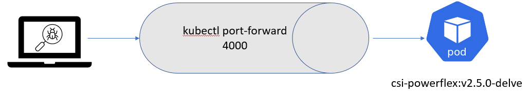
Compilation
Base image
First, it is important to know that Dell and RedHat are partners, and all CSI/CSM containers are certified by RedHat.
This comes with a couple of constraints, one being that all containers use the Red Hat UBI Minimal image as a base image and, to be certified, extra packages must come from a Red Hat official repo.
CSI PowerFlex needs the e4fsprogs package to format file systems in ext4, and that package is missing from the default UBI repo. To install it, you have these options:
- If you build the image from a registered and subscribed RHEL host, the repos of the server are automatically accessible from the UBI image. This only works with podman build.
- If you have a Red Hat Satellite subscription, you can update the Dockerfile to point to that repo.
- You can use a third-party repository.
- You go the old way and compile the package yourself (the source of that package is in UBI source-code repo).
Here we’ll use an Oracle Linux mirror, which allows us to access binary-compatible packages without the need for registration or payment of a Satellite subscription.
The Oracle Linux 8 repo is:
[oracle-linux-8-baseos]
name=Oracle Linux 8 - BaseOS
baseurl=http://yum.oracle.com/repo/OracleLinux/OL8/baseos/latest/x86_64
gpgcheck = 0
enabled = 1
And we add it to final image in the Dockerfile with a COPY directive:
# Stage to build the driver image
FROM $BASEIMAGE@${DIGEST} AS final
# install necessary packages
# alphabetical order for easier maintenance
COPY ol-8-base.repo /etc/yum.repos.d/
RUN microdnf update -y && \
...
Delve
There are several debugger options available for Go. You can use the venerable GDB, a native solution like Delve, or an integrated debugger in your favorite IDE.
For our purposes, we prefer to use Delve because it allows us to connect to a remote Kubernetes cluster.
Our Dockerfile employs a multi-staged build approach. The first stage is for building (and named builder) from the Golang image; we can add Delve with the directive:
RUN go install github.com/go-delve/delve/cmd/dlv@latest
And then compile the driver.
On the final image that is our driver, we add the binary as follows:
# copy in the driver
COPY --from=builder /go/src/csi-vxflexos /
COPY --from=builder /go/bin/dlv /
In the build stage, we download Delve with:
RUN go get github.com/go-delve/delve/cmd/dlv
In the final image we copy the binary with:
COPY --from=builder /go/bin/dlv /
To achieve better results with the debugger, it is important to disable optimizations when compiling the code.
This is done in the Makefile with:
CGO_ENABLED=0 GOOS=linux GO111MODULE=on go build -gcflags "all=-N -l"
After rebuilding the image with make docker and pushing it to your registry, you need to expose the Delve port for the driver container. You can do this by adding the following lines to your Helm chart. We need to add the lines to the driver container of the Controller Deployment.
          ports:
          - containerPort: 40000
Alternatively, you can use the kubectl edit -n powerflex deployment command to modify the Kubernetes deployment directly.
Usage
Assuming that the build has been completed successfully and the driver is deployed on the cluster, we can expose the debugger socket locally by running the following command:
kubectl port-forward -n powerflex pod/csi-powerflex-controller-uid 40000:40000
Next, we can open the project in our favorite IDE and ensure that we are on the same branch that was used to build the driver.
In the following screenshot I used Goland, but VSCode can do remote debugging too.
We can now connect the IDE to that forwarded socket and run the debugger live:
And here is the result of a breakpoint on CreateVolume call: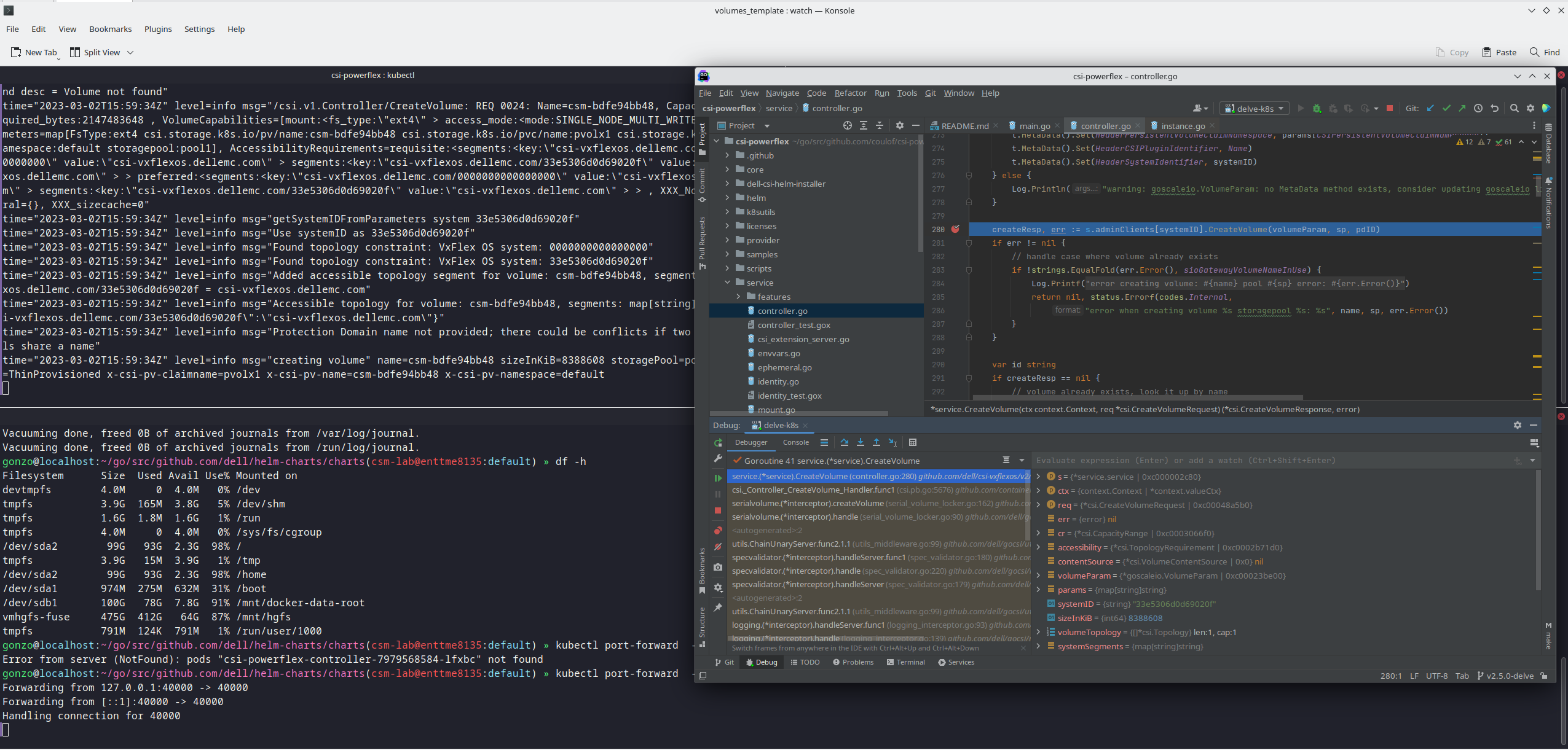
The full code is here: https://github.com/dell/csi-powerflex/compare/main...coulof:csi-powerflex:v2.5.0-delve.
If you liked this information and need more deep-dive details on Dell CSI and CSM, feel free to reach out at https://dell-iac.slack.com.
Author: Florian Coulombel

Introducing Terraform Provider for PowerMax v1.0

Mon, 13 Mar 2023 19:06:05 -0000
|Read Time: 0 minutes
There are a number of tools for managing your Infrastructure as Code, from Basic REST API commands that you can script together in the language of your choice to more sophisticated engine tools like Ansible, Terraform, Chef, SaltStack or Cloud Formation.
Dell already provides comprehensive support for REST API and Ansible Collections for Dell storage arrays and is now releasing providers for Terraform for server and storage products. (A Terraform provider is a plugin that enables Terraform to interact with the vendor API.) Initially Dell will publish providers for PowerMax, PowerStore, and PowerFlex storage on Terraform registry to enable user access to published resources to manage these storage arrays.
Terraform is an open-source infrastructure-as-code software tool created by HashiCorp. In Terraform, users define data center infrastructure using a declarative configuration language known as HashiCorp Configuration Language (HCL), which is relatively simple and similar to YAML. Terraform encourages a declarative style where you write code that describes your desired end state of your configuration, and Terraform figures out how to get to that end state. Terraform is also aware of any state it created in the past as it tracks whether the configuration is a state file stored locally or in version control.
A Terraform configuration is a complete document in the Terraform language that tells Terraform how to manage a given collection of infrastructure. A configuration can consist of multiple files and directories. This blog takes you through a basic configuration with the PowerMax provider.
(Note: Sample code is published on the Dell GitHub page where the Terraform provider is hosted. This first PowerMax provider for Terraform concentrates on storage provisioning operations, creating masking views, and managing the storage volumes for your applications. More features will come online with later releases based on customer feedback.)
Setting up the PowerMax provider for Terraform
Before configuring anything, it is important to note that the Terraform provider will communicate with Unisphere for PowerMax using REST. At a minimum you will need a user account with storage administrator privileges for the arrays that you need to manage.
To start working with Terraform you will need to install Terraform. See Terraform guides for official documentation. In my case, the host was Red Hat so I simply ran
yum install terraform
After you have installed Terraform, you need to set up any third-party providers you will work with. These are located on the Terraform registry (think of it as an Appstore).
To install the PowerMax provider, copy and paste the code snippet from the Use Provider link for your Terraform configuration file. For example:
terraform {
  required_providers {
    powermax = {
      source = "dell/powermax"
      version = "1.0.0-beta"
    }
  }
}
provider "powermax" {
  # Configuration options
}
In my case, I have a flat directory structure with a few files in it. The first file is provider.tf that contains this text shown here.
When the provider file has the required code for the vendor providers, run
terraform init
At this point, the system is set up and ready to run Terraform with PowerMax storage.
Defining PowerMax configurations in Terraform
With Terraform installed and and the provider set up, we now need to explore the other files we’ll need to manage a configuration with Terraform.
All Terraform configurations store configuration in a state file (usually terraform.tfstate). This file keeps track of configuration information about managed objects and is used for the idempotency features of Terraform configurations. The state file can be local to the Terraform host but if you have multiple users, or if you are using automation and CI/CD pipelines to run Terraform, the state file needs to be accessible, place the state file on shared storage. Grant permissions as needed. Here’s what my state file looks like, pointing to a shared storage location on an S3 bucket:
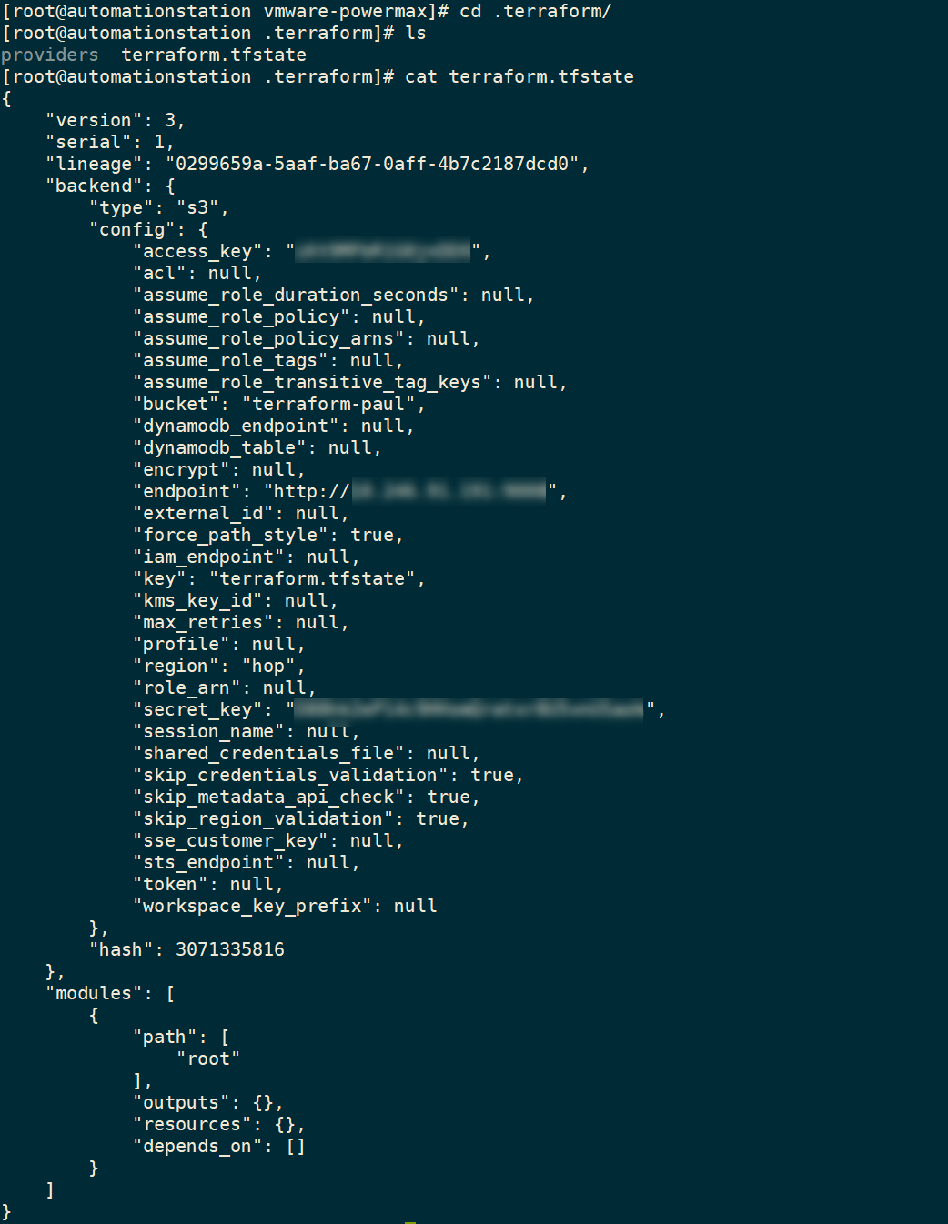
Now that we’ve set up a shared state file, I can create my configurations for managing my PowerMax Storage configurations.
Creating configurations in Terraform for PowerMax
There are three stages to creating a configuration with Terraform:
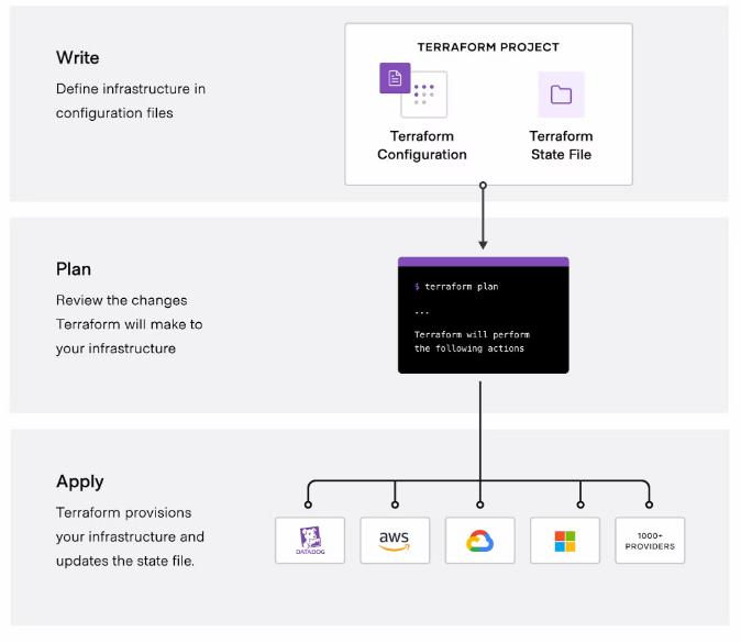
(Image credit https://developer.hashicorp.com/terraform/intro.)
Write the configuration
To write configuration files for PowerMax infrastructure, you can use the sample code snippets for each of the resources, available on the Terraform registry or on the Dell GitHub for the Terraform provider. You can copy and customize the code to meet your requirements.
In the following example configuration, the file defines resources for the storage group, volumes, masking view, port group, host, and host group. The configuration also defines some VMware resources to create a datastore from the newly configured PowerMax device.
resource "powermax_storage_group" "tmevcenter_sg" {
  name          = "tmevcenter_sg"
  srpid         = "SRP_1"
  service_level = "Diamond"
}
resource "powermax_host_group" "BETA_CLUSTER" {
  name       ="BETA_CLUSTER"
  host_flags = {}
  host_ids   = ["DELL52", "DELL55"]
}
resource "powermax_host" "DELL52" {
  name       = "DELL52"
  initiators = [
               "100000109b56a004",
               "100000109b56a007"]
  host_flags = {}
}
resource "powermax_host" "DELL55" {
  name       = "DELL55"
  initiators = [
                 "100000109b56a016",
                "100000109b56a0ca"]
  host_flags = {}
}
resource "powermax_port_group" "tmevcenter_pg" {
  name     = "tmevcenter_pg"
  protocol = "SCSI_FC"
  ports = [
    {
      director_id = "OR-1C"
      port_id     = "0"
    },
    {
      director_id = "OR-2C"
      port_id      = "0"
    },
    {
      director_id = "OR-2C"
      port_id     = "1"
    },
    {
      director_id = "OR-2C"
      port_id     = "1"
    }
  ]
}
resource "powermax_volume" "volume_1" {
  name               = "vcenter_ds_by_terraform_volume_1"
  size               = 20
  cap_unit           = "GB"
  sg_name            = "tmevcenter_sg"
  enable_mobility_id = false
}
resource "powermax_masking_view" "tmevcenter_mv" {
  name           ="tmevcenter_mv"
  storage_group_id = powermax_storage_group.tmevcenter_sg.id
  port_group_id = powermax_port_group.tmevcenter_pg.id
  host_group_id = powermax_host_group.BETA_CLUSTER.id
}
data "vsphere_vmfs_disks" "available" {
  host_system_id = data.vsphere_host.main_esxi_host.id
  rescan         = true
  filter         = "naa"
}
resource "vsphere_vmfs_datastore" "datastore" {
  name           = "terraform-test"
  host_system_id = data.vsphere_host.main_esxi_host.id
  disks = ["naa.${lower(powermax_volume.volume_1.wwn)}"]
}
Plan the configuration
Running the plan command from the configuration directory will output any changes needed on the PowerMax array and vCenter without executing. You can compare the plan against your change requests to ensure that it will produce the expected results.
terraform plan
The following output from the terraform plan command shows objects that will be created by applying the plan outlined in the configuration.
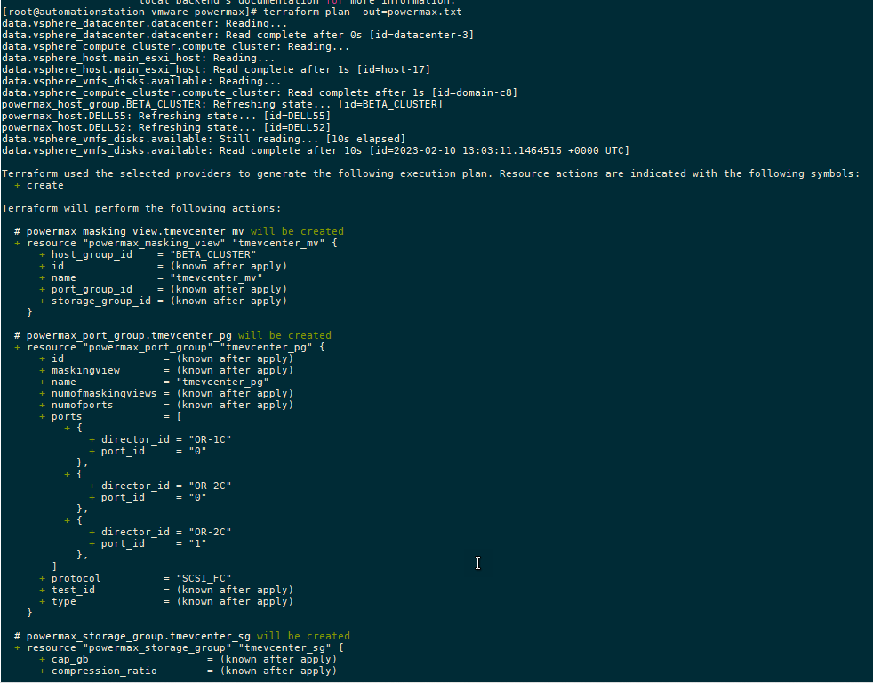
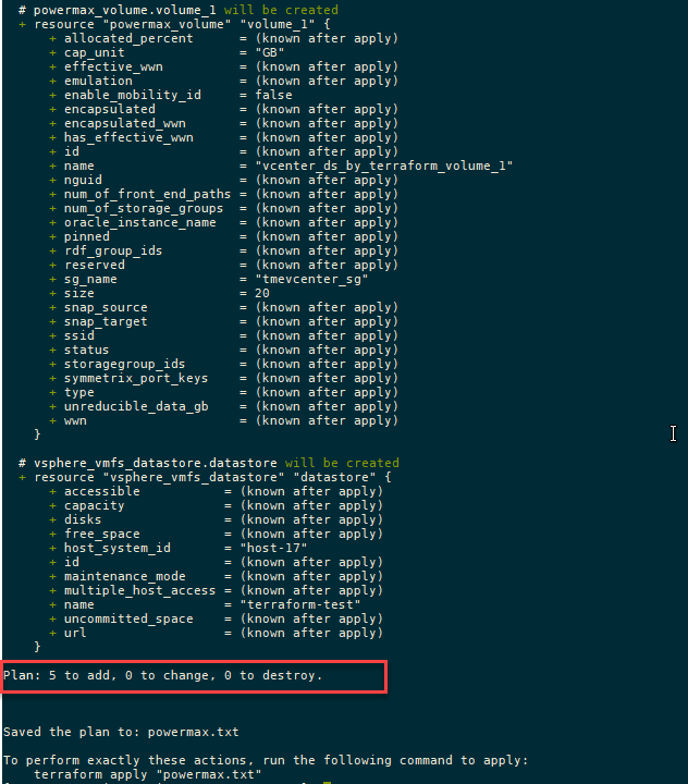
After creating the plan, we get a summary of the output. In this case, Terraform will add five objects and create the datastore, storage group, volumes, port group, and masking view.
A note about working with existing storage objects
If you are working with existing objects, you must import them into the Terraform state file before applying and executing your configuration. To do this, run terraform import command.
For example, to import a host group resource called MY_CLUSTER, specify:
terraform import powermax_host_group.MY_CLUSTER MY_CLUSTER
To view the state of any managed object in your state file, you can check it with the terraform state show command, as shown here:
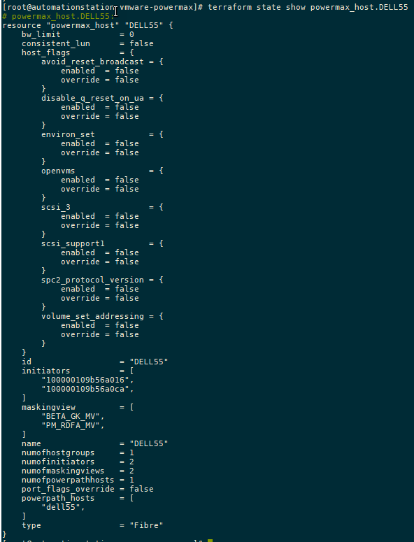
Apply the configuration
Executing the plan with the apply command runs the configuration changes:
terraform apply
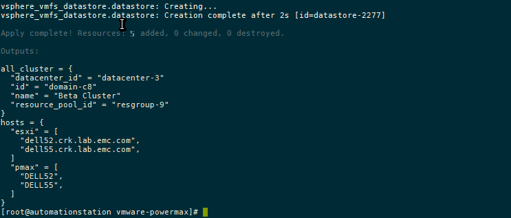
Conclusion
As I mentioned earlier, this is the first installment of the Terraform provider for PowerMax. As you can see, the main functionality is around the provisioning of storage. In future releases we’ll add more functionality.
To provide any feedback, use the issues section on the GitHub. If you are already using Terraform to manage your configuration, the PowerMax provider will no doubt prove useful in assisting your automation journey!
Authors: Paul Martin, Florian Coulombel

Getting Started with REST API
Fri, 27 Jan 2023 18:41:52 -0000
|Read Time: 0 minutes
What is REST API?
REST stands for Representational State Transfer, and it is an architectural style for building APIs, or application programming interfaces. JSON stands for JavaScript Object Notation, a lightweight format for storing and transmitting data between a server and a client application. REST and JSON are popular technologies in building web APIs.
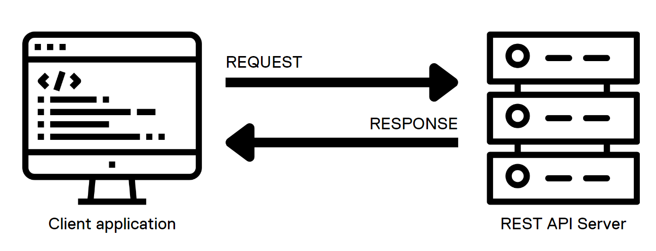 .
.
HTML methods in REST API calls
The server interface for a REST API is organized as resources that can be accessed through a uniform resource identifier (URI) to access resources and perform actions. HTTP methods like GET and PUT perform one of CRUD: CREATE, READ, UPDATE and DELETE operations on the resources.
REST API calls can be used from almost any modern programming language with the following HTTP methods to communicate with the web server:
- GET: the GET method is used to retrieve a resource from the server. It is heavily used for things like loading a dynamic web page. When used programmatically, the output of this method is captured in a variable of the programming language and then parsed to retrieve different components of the output.
- PUT: the PUT method is used to create or update an existing resource on the server. Note that the body of the request should contain the entire object structure of the resource. When the resource doesn’t exist, PUT creates a new resource.
- POST: the POST method is used to create a new resource on the server. The body of a POST request has all the details of the new record and is usually validated on the server side for expected type of data and completeness of the record. Note that the main difference between POST and PUT is that PUT requests are idempotent. That is, calling the same PUT request multiple times will always produce the same result. By contrast, calling a POST request repeatedly creates the same resource multiple times.
- DELETE: the DELETE method is used to delete a resource.
- PATCH: The PATCH method is used to apply partial modifications to a resource. Unlike PUT requests, PATCH requests apply a partial update to the resource.
JSON and the anatomy of a REST API call
In response to the API calls, the web service provides a response in JSON format. JSON is a lightweight, human-readable format for representing structured data. The response includes the status of the call, information requested, and any errors using specific codes. This response is further parsed and processed by the client application.
Here is how a simple GET request looks like when used on a shell CLI with the CURL command:
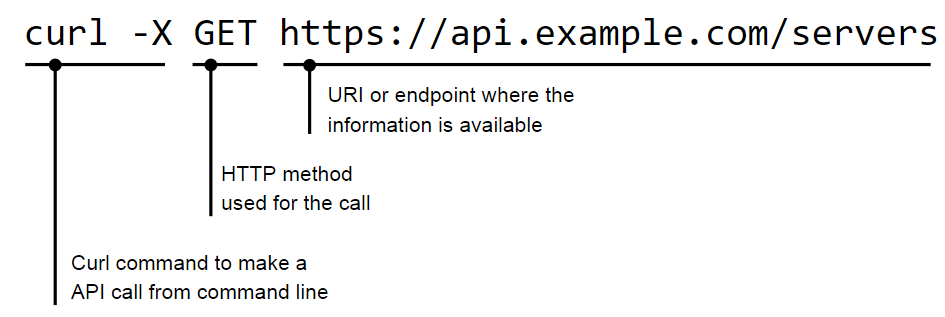
The JSON response to a call is provided in a <name>:<value> format:
  "servers": [
    {
      "id": 123,
      "name": "alice"
    },
    {
      "id": 456,
      "name": "bob"
    }
  ]
}
JSON supports nested structures, which allow an object or array to contain other objects and arrays. For example, consider the following JSON data:
{
    "name": "John Doe",
    "age": 35,
    "address": {
        "street": "123 Main St",
        "city": "New York",
        "state": "NY"
    },
     "phoneNumbers": [
        {
             "type": "home",
            "number": "212-555-1212"
        },
        {
             "type": "office",
             "number": "646-555-1212"
        }
    ]
}
HTTP return codes
In a REST API, HTTP status codes indicate the outcome of an API request. Here are some common HTTP status codes that a REST API might return, along with their meanings and suggestions for how a client application could handle them:
- 200 OK: The request was successful! The response body contains the requested data. The client can continue to process the response as normal.
- 201 Created: The request resulted in the creation of a new resource. The response body may contain the newly created resource; the Location header of the response will contain the URL of the new resource. The client should store this URL for future reference.
- 204 No Content: The request was successful, but the response body is empty. The client should continue processing as normal, but should not try to parse the response body.
- 400 Bad Request: The request was not valid, for example because it contained invalid parameters or was missing required data. The response body may contain more detailed error information. The client should check the error details and adjust the request as needed before trying again.
- 401 Unauthorized: The request requires the client to authenticate itself, but the client did not provide a valid authentication token. The client should prompt the user for their credentials and try the request again with a valid authentication token.
- 404 Not Found: The requested resource does not exist. The client should check that the URL of the request is correct and adjust it if necessary before trying again.
- 500 Internal Server Error: The server encountered an unexpected error while processing the request. The client should try the request again at a later time, because the issue may be temporary.
Client applications must handle these different HTTP status codes properly to provide a good user experience. For example, if a client receives a 404 Not Found error, it could display a message to the user indicating that the requested resource was not found, rather than just displaying an empty screen.
Authentication
There are several popular authentication mechanisms for REST APIs, including:
1. Basic authentication: This simple authentication scheme uses a username and password to authenticate a user. The username and password are typically sent in the request header.
curl -X GET 'https://api.example.com/server' \
   -H 'Content-Type: application/json' \
   -H 'Authorization: Basic dXNlcm5hbWU6cGFzc3dvcmQ='
In this example, the Authorization header is set to Basic dXNlcm5hbWU6cGFzc3dvcmQ=, where dXNlcm5hbWU6cGFzc3dvcmQ= is the base64-encoded representation of the string username:password.
2. Token-based authentication: In this scheme, the client exchanges a username and password for a token. The token is then included in subsequent requests to authenticate the user.
curl -X GET 'https://api.example.com/users' \
   -H 'Content-Type: application/json' \
   -H 'Authorization: Bearer abc123'
In this example, the Authorization header is set to Bearer abc123, where abc123 is the token that was issued to the client.
3. OAuth: This open-standard authorization framework provides a way for users to authorize access to APIs securely. OAuth involves a client, a resource server, and an authorization server.
4. OpenID Connect: This is a protocol built on top of OAuth 2.0 that provides a way to authenticate users using a third-party service, such as Google or Facebook.
Resources
The Dell Technologies infrastructure portfolio has extensive APIs covering all IT infrastructure operations. You can learn more about the API implementation of the different Dell infrastructure products on the Info Hub:
- PowerStore REST API: Using Filtering to Fine Tune Your Queries
- REST API examples for PowerMax snapshot operations
- REST - The Power of Network Automation Using REST APIs
- ECS Management REST API: Postman Collection
- VxRail API—Updated List of Useful Public Resources
- What’s New in PowerMax REST API 10.0
You can also explore Dell infrastructure APIs by visiting the API documentation portal: https://developer.dell.com/apis.
Authors: Florian Coulombel and Parasar Kodati

Dell Container Storage Modules—A GitOps-Ready Platform!
Thu, 26 Jan 2023 19:04:30 -0000
|Read Time: 0 minutes
One of the first things I do after deploying a Kubernetes cluster is to install a CSI driver to provide persistent storage to my workloads; coupled with a GitOps workflow; it takes only seconds to be able to run stateful workloads.
The GitOps process is nothing more than a few principles:
- Git as a single source of truth
- Resource explicitly declarative
- Pull based
Nonetheless, to ensure that the process runs smoothly, you must make certain that the application you will manage with GitOps complies with these principles.
This article describes how to use the Microsoft Azure Arc GitOps solution to deploy the Dell CSI driver for Dell PowerMax and affiliated Container Storage Modules (CSMs).
The platform we will use to implement the GitOps workflow is Azure Arc with GitHub. Still, other solutions are possible using Kubernetes agents such as Argo CD, Flux CD, and GitLab.
Azure GitOps itself is built on top of Flux CD.
Install Azure Arc
The first step is to onboard your existing Kubernetes cluster within the Azure portal.
Obviously, the Azure agent will connect to the Internet. In my case, the installation of the Arc agent fails from the Dell network with the error described here: https://docs.microsoft.com/en-us/answers/questions/734383/connect-openshift-cluster-to-azure-arc-secret-34ku.html
Certain URLs (even when bypassing the corporate proxy) don't play well when communicating with Azure. I have seen some services get a self-signed certificate, causing the issue.
The solution for me was to put an intermediate transparent proxy between the Kubernetes cluster and the corporate cluster. That way, we can have better control over the responses given by the proxy.

In this example, we install Squid on a dedicated box with the help of Docker. To make it work, I used the Squid image by Ubuntu and made sure that Kubernetes requests were direct with the help of always_direct:
docker run -d --name squid-container ubuntu/squid:5.2-22.04_beta ; docker cp squid-container:/etc/squid/squid.conf ./ ; egrep -v '^#' squid.conf > my_squid.conf
docker rm -f squid-container
Then add the following section:
acl k8s        port 6443        # k8s https
always_direct allow k8s
You can now install the agent per the following instructions: https://docs.microsoft.com/en-us/azure/azure-arc/kubernetes/quickstart-connect-cluster?tabs=azure-cli#connect-using-an-outbound-proxy-server.
export HTTP_PROXY=http://mysquid-proxy.dell.com:3128
export HTTPS_PROXY=http://mysquid-proxy.dell.com:3128
export NO_PROXY=https://kubernetes.local:6443

az connectedk8s connect --name AzureArcCorkDevCluster \
                        --resource-group AzureArcTestFlorian \
                        --proxy-https http://mysquid-proxy.dell.com:3128 \
                        --proxy-http http://mysquid-proxy.dell.com:3128 \
                        --proxy-skip-range 10.0.0.0/8,kubernetes.default.svc,.svc.cluster.local,.svc \
                        --proxy-cert /etc/ssl/certs/ca-bundle.crt
If everything worked well, you should see the cluster with detailed info from the Azure portal:
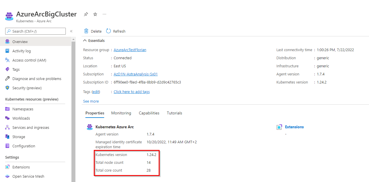
Add a service account for more visibility in Azure portal
To benefit from all the features that Azure Arc offers, give the agent the privileges to access the cluster.
The first step is to create a service account:
kubectl create serviceaccount azure-user
kubectl create clusterrolebinding demo-user-binding --clusterrole cluster-admin --serviceaccount default:azure-user
kubectl apply -f - <<EOF
apiVersion: v1
kind: Secret
metadata:
  name: azure-user-secret
  annotations:
    kubernetes.io/service-account.name: azure-user
type: kubernetes.io/service-account-token
EOF
Then, from the Azure UI, when you are prompted to give a token, you can obtain it as follows:
kubectl get secret azure-user-secret -o jsonpath='{$.data.token}' | base64 -d | sed $'s/$/\\\n/g'Then paste the token in the Azure UI.
Install the GitOps agent
The GitOps agent installation can be done with a CLI or in the Azure portal.
As of now, the Microsoft documentation presents in detail the deployment that uses the CLI; so let's see how it works with the Azure portal:
Organize the repository
The Git repository organization is a crucial part of the GitOps architecture. It hugely depends on how internal teams are organized, the level of information you want to expose and share, the location of the different clusters, and so on.
In our case, the requirement is to connect multiple Kubernetes clusters owned by different teams to a couple of PowerMax systems using only the latest and greatest CSI driver and affiliated CSM for PowerMax.
Therefore, the monorepo approach is suited.
The organization follows this structure:
.
├── apps
│ ├── base
│ └── overlays
│ ├── cork-development
│ │ ├── dev-ns
│ │ └── prod-ns
│ └── cork-production
│ └── prod-ns
├── clusters
│ ├── cork-development
│ └── cork-production
└── infrastructure
├── cert-manager
├── csm-replication
├── external-snapshotter
└── powermax
- apps: Contains the applications to be deployed on the clusters.
- We have different overlays per cluster.
- cluster: Usually contains the cluster-specific Flux CD main configuration; using Azure Arc, none is needed.
- Infrastructure: Contains the deployments that are used to run the infrastructure services; they are common to every cluster.
- cert-manager: Is a dependency of powermax reverse-proxy
- csm-replication: Is a dependency of powermax to support SRDF replication
- external-snapshotter: Is a dependency of powermax to snapshot
- powermax: Contains the driver installation
You can see all files in https://github.com/coulof/fluxcd-csm-powermax.
Note: The GitOps agent comes with multi-tenancy support; therefore, we cannot cross-reference objects between namespaces. The Kustomization and HelmRelease must be created in the same namespace as the agent (here, flux-system) and have a corresponding targetNamespace to the resource to be installed.
Conclusion
This article is the first of a series exploring the GitOps workflow. Next, we will see how to manage application and persistent storage with the GitOps workflow, how to upgrade the modules, and so on.
Resources

Dell Container Storage Modules 1.5 Release
Thu, 12 Jan 2023 19:27:23 -0000
|Read Time: 0 minutes
Made available on December 20th, 2022, the 1.5 release of our flagship cloud-native storage management products, Dell CSI Drivers and Dell Container Storage Modules (CSM), is here!
See the official changelog in the CHANGELOG directory of the CSM repository.
First, this release extends support for Red Hat OpenShift 4.11 and Kubernetes 1.25 to every CSI Driver and Container Storage Module.
Featured in the previous CSM release (1.4), avid customers may recall a few new additions to the portfolio made available in tech preview. Primarily:
- CSM Application Mobility: Enables the movement of Kubernetes resources and data from one cluster to another no matter the source and destination (on-prem, co-location, cloud) and any type of backend storage (Dell or non-Dell)
- CSM Secure: Allows for on-the-fly encryption of PV data
- CSM Operator: Manages CSI and CSM as a single stack
Building on these three new modules, Dell Technologies is adding deeper capabilities and major improvements as part of today’s 1.5 release for CSM, including:
- CSM Application Mobility: Users can now schedule backups
- CSM Secure: Users can now “rekey” an encrypted PV
- CSM Operator: Support added for Dell’s PowerFlex CSI Driver, the Authorization Proxy Server, and the CSM Observability module for Dell PowerFlex and Dell PowerScale
For the platform updates included in today’s 1.5 release, the major new features are:
- It is now possible to set the Quality of Service of a Dell PowerFlex persistent volume. Two new parameters can be set in the StorageClass (bandwidthLimitInKbps and iopsLimit) to limit the consumption of a volume. Watch this short video to learn how it works.
- For Dell PowerScale, when a Kubernetes node is decommissioned from the cluster, the NFS export created by the driver will “Ignore the Unresolvable Hosts” and clean them later.
- Last but not least, when you have a Kubernetes cluster that runs on top of Virtual Machines backed by VMware, the CSI driver can mount FiberChannel attached LUNs.
This feature is named “Auto RDM over FC” in the CSI/CSM documentation.
The concept is that the CSI driver will connect to both Unisphere and vSphere API to create the respective objects.
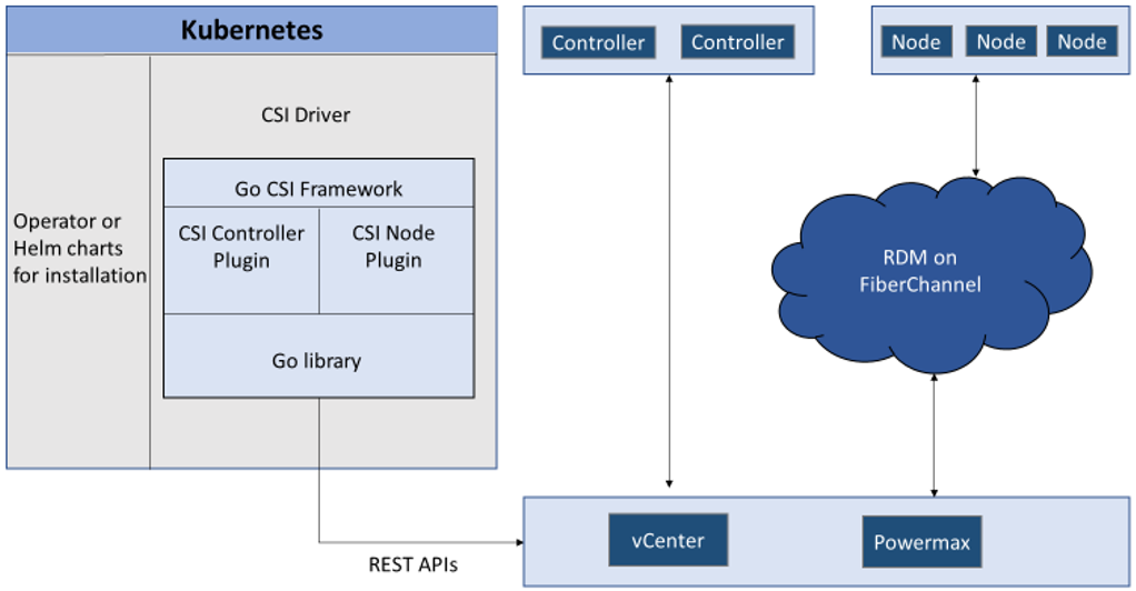
When deployed with “Auto-RDM” the driver can only function in that mode. It is not possible to combine iSCSI and FC access within the same driver installation.
The same limitation applies for RDM usage. You can learn more about it at RDM Considerations and Limitations on the VMware website.
That’s all for CSM 1.5! Feel free to share feedback or send questions to the Dell team on Slack: https://dell-csm.slack.com.
Author: Florian Coulombel

Velero Backup to PowerScale S3 Bucket
Fri, 23 Dec 2022 21:50:39 -0000
|Read Time: 0 minutes
Velero is one of the most popular tools for backup and restore of Kubernetes resources.
You can use Velero for different backup options to protect your Kubernetes cluster. The three modes are:
- Protect the Kubernetes resource objects such as Pod, Namespace, and so on, with CRDs included
- Protect the PersistentVolume data with the help of VolumeSnapshot
- Protect the content of the PVs with the help of restic
In all cases, Velero syncs the information (YAML and restic data) to a storage object.
PowerScale is Dell Technologies’ leading scale-out NAS solution. It supports many different access protocols including NFS, SMB, HTTP, FTP, HDFS, and, in the case that interests us, S3!
Note: PowerScale is not 100% compatible with the AWS S3 protocol (for details, see the PowerScale OneFS S3 API Guide).
For a simple backup solution of a few terabytes of Kubernetes data, PowerScale and Velero are a perfect duo.
Deployment
To deploy this solution, you need to configure PowerScale and then install and configure Velero.
PowerScale S3 configuration
Prepare PowerScale to be a target for the backup as follows:
- Make sure the S3 protocol is enabled.
You can check that in the UI under Protocols > Object Storage (S3) > Global Settings or in the CLI.
In the UI:
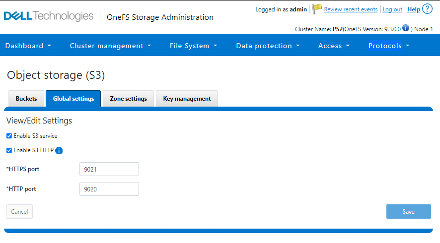
In the CLI:
PS1-1% isi s3 settings global view
         HTTP Port: 9020
        HTTPS Port: 9021
        HTTPS only: No
S3 Service Enabled: Yes
2. Create a bucket with the permission to write objects (at a minimum).
That action can also be done from the UI or CLI.
In the UI:
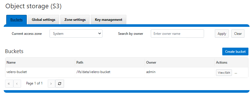
In the CLI:
See isi S3 buckets create in the PowerScale OneFS CLI Command Reference.
3. Create a key for the user that will be used to upload the objects.
Important notes:
- The username is the one indicated in the interface, not the one from the file system or provider (for example, here, the admin user is 1_admin_accid S3 user)
- The key is only displayed upon creation and cannot be retrieved later. Be sure to copy it right away.
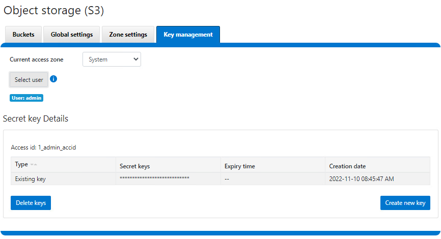
Now that PowerScale is ready, we can proceed with the Velero deployment.
Velero installation and configuration
We assume that the Velero binary is installed and has access to the Kubernetes cluster. If not, see the Velero installation document for the deployment instructions.
Configure Velero:
- Create a file with the credentials previously obtained from PowerScale.
$ cat ~/credentials-velero
[default]
aws_access_key_id = 1_admin_accid
aws_secret_access_key = 0**************************i
…
- Optionally, obtain the PowerScale SSL certificate.
In our case, the HTTPS endpoint uses a self-signed certificate, so we have to get it and pass it to Velero. Note that we can use HTTP protocol, and that step can be skipped at the cost of plain text data transit. For more information on the self-signed certificates in the context of Velero, see https://velero.io/docs/v1.9/self-signed-certificates/. - Install Velero itself:
$ velero install \
    --provider aws \
    --plugins velero/velero-plugin-for-aws:v1.5.1 \
    --bucket velero-backup \
    --secret-file ./credentials-velero \
    --use-volume-snapshots=false \
    --cacert ./ps2-cacert.pem \
    --backup-location-config region=powerscale,s3ForcePathStyle="true",s3Url=https://192.168.1.21:9021
…
The preceding command shows how to use Velero most simplistically and securely.
It is possible to add parameters to enable protection with snapshots. Every Dell CSI driver has snapshot support. To take advantage of that support, we use the install command with this addition:
velero install \
--features=EnableCSI \
--plugins=velero/velero-plugin-for-aws:v1.5.1,velero/velero-plugin-for-csi:v0.3.0 \
--use-volume-snapshots=true
...
Now that CSI snaps are enabled, we can enable restic to move data out of those snapshots into our backup target by adding:
--use-restic
As you can see, we are using the velero/velero-plugin-for-aws:v1.5.1 image, which is the latest available at the time of the publication of this article. You can obtain the current version from GitHub: https://github.com/vmware-tanzu/velero-plugin-for-aws
After the Velero installation is done, check that everything is correct:
kubectl logs -n velero deployment/velero
If you have an error with the certificates, you should see it quickly.
You can now back up and restore your Kubernetes resources with the usual Velero commands. For example, to protect the entire Kubernetes except kube-system, including the data with PV snapshots:
velero backup create backup-all --exclude-namespaces kube-system
You can check the actual content directly from PowerScale file system explorer:
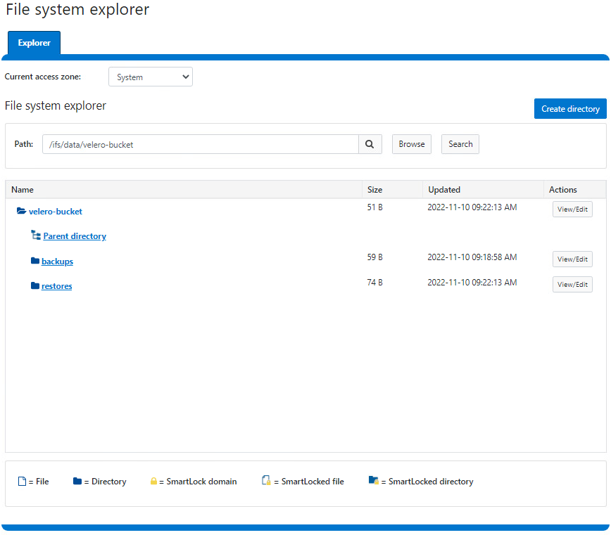
Here is a demo:
Conclusion
For easy protection of small Kubernetes clusters, Velero combined with PowerScale S3 is a great solution. If you are looking for broader features (for a greater amount of data or more destinations that go beyond Kubernetes), look to Dell PowerProtect Data Manager, a next-generation, comprehensive data protection solution.
Interestingly, Dell PowerProtect Data Manager uses the Velero plug-in to protect Kubernetes resources!
Resources

Dell Container Storage Modules—A GitOps-Ready Platform!
Mon, 26 Sep 2022 15:17:45 -0000
|Read Time: 0 minutes
One of the first things I do after deploying a Kubernetes cluster is to install a CSI driver to provide persistent storage to my workloads; coupled with a GitOps workflow; it takes only seconds to be able to run stateful workloads.
The GitOps process is nothing more than a few principles:
- Git as a single source of truth
- Resource explicitly declarative
- Pull based
Nonetheless, to ensure that the process runs smoothly, you must make certain that the application you will manage with GitOps complies with these principles.
This article describes how to use the Microsoft Azure Arc GitOps solution to deploy the Dell CSI driver for Dell PowerMax and affiliated Container Storage Modules (CSMs).
The platform we will use to implement the GitOps workflow is Azure Arc with GitHub. Still, other solutions are possible using Kubernetes agents such as Argo CD, Flux CD, and GitLab.
Azure GitOps itself is built on top of Flux CD.
Install Azure Arc
The first step is to onboard your existing Kubernetes cluster within the Azure portal.
Obviously, the Azure agent will connect to the Internet. In my case, the installation of the Arc agent fails from the Dell network with the error described here: https://docs.microsoft.com/en-us/answers/questions/734383/connect-openshift-cluster-to-azure-arc-secret-34ku.html
Certain URLs (even when bypassing the corporate proxy) don't play well when communicating with Azure. I have seen some services get a self-signed certificate, causing the issue.
The solution for me was to put an intermediate transparent proxy between the Kubernetes cluster and the corporate cluster. That way, we can have better control over the responses given by the proxy.
In this example, we install Squid on a dedicated box with the help of Docker. To make it work, I used the Squid image by Ubuntu and made sure that Kubernetes requests were direct with the help of always_direct:
docker run -d --name squid-container ubuntu/squid:5.2-22.04_beta ; docker cp squid-container:/etc/squid/squid.conf ./ ; egrep -v '^#' squid.conf > my_squid.conf
docker rm -f squid-container
Then add the following section:
acl k8s        port 6443        # k8s https
always_direct allow k8s
You can now install the agent per the following instructions: https://docs.microsoft.com/en-us/azure/azure-arc/kubernetes/quickstart-connect-cluster?tabs=azure-cli#connect-using-an-outbound-proxy-server.
export HTTP_PROXY=http://mysquid-proxy.dell.com:3128
export HTTPS_PROXY=http://mysquid-proxy.dell.com:3128
export NO_PROXY=https://kubernetes.local:6443

az connectedk8s connect --name AzureArcCorkDevCluster \
                        --resource-group AzureArcTestFlorian \
                        --proxy-https http://mysquid-proxy.dell.com:3128 \
                        --proxy-http http://mysquid-proxy.dell.com:3128 \
                        --proxy-skip-range 10.0.0.0/8,kubernetes.default.svc,.svc.cluster.local,.svc \
                        --proxy-cert /etc/ssl/certs/ca-bundle.crt
If everything worked well, you should see the cluster with detailed info from the Azure portal:
Add a service account for more visibility in Azure portal
To benefit from all the features that Azure Arc offers, give the agent the privileges to access the cluster.
The first step is to create a service account:
kubectl create serviceaccount azure-user
kubectl create clusterrolebinding demo-user-binding --clusterrole cluster-admin --serviceaccount default:azure-user
kubectl apply -f - <<EOF
apiVersion: v1
kind: Secret
metadata:
  name: azure-user-secret
  annotations:
    kubernetes.io/service-account.name: azure-user
type: kubernetes.io/service-account-token
EOF
Then, from the Azure UI, when you are prompted to give a token, you can obtain it as follows:
kubectl get secret azure-user-secret -o jsonpath='{$.data.token}' | base64 -d | sed $'s/$/\\\n/g'Then paste the token in the Azure UI.
Install the GitOps agent
The GitOps agent installation can be done with a CLI or in the Azure portal.
As of now, the Microsoft documentation presents in detail the deployment that uses the CLI; so let's see how it works with the Azure portal:
Organize the repository
The Git repository organization is a crucial part of the GitOps architecture. It hugely depends on how internal teams are organized, the level of information you want to expose and share, the location of the different clusters, and so on.
In our case, the requirement is to connect multiple Kubernetes clusters owned by different teams to a couple of PowerMax systems using only the latest and greatest CSI driver and affiliated CSM for PowerMax.
Therefore, the monorepo approach is suited.
The organization follows this structure:
.
├── apps
│ ├── base
│ └── overlays
│ ├── cork-development
│ │ ├── dev-ns
│ │ └── prod-ns
│ └── cork-production
│ └── prod-ns
├── clusters
│ ├── cork-development
│ └── cork-production
└── infrastructure
├── cert-manager
├── csm-replication
├── external-snapshotter
└── powermax
- apps: Contains the applications to be deployed on the clusters.
- We have different overlays per cluster.
- cluster: Usually contains the cluster-specific Flux CD main configuration; using Azure Arc, none is needed.
- Infrastructure: Contains the deployments that are used to run the infrastructure services; they are common to every cluster.
- cert-manager: Is a dependency of powermax reverse-proxy
- csm-replication: Is a dependency of powermax to support SRDF replication
- external-snapshotter: Is a dependency of powermax to snapshot
- powermax: Contains the driver installation
You can see all files in https://github.com/coulof/fluxcd-csm-powermax.
Note: The GitOps agent comes with multi-tenancy support; therefore, we cannot cross-reference objects between namespaces. The Kustomization and HelmRelease must be created in the same namespace as the agent (here, flux-system) and have a corresponding targetNamespace to the resource to be installed.
Conclusion
This article is the first of a series exploring the GitOps workflow. Next, we will see how to manage application and persistent storage with the GitOps workflow, how to upgrade the modules, and so on.
Resources
- Tutorial: Implement CI/CD with GitOps (Flux v2)
- GitOps Flux v2 configurations with AKS and Azure Arc-enabled Kubernetes