


PowerEdge MX7000 100 GbE Networking
Tue, 09 May 2023 14:01:03 -0000
|Read Time: 0 minutes
100 Gigabit Ethernet networking has arrived on the Dell PowerEdge Platform! The Dell Networking MX8116n Fabric Expander Module is now available to deploy with the PowerSwitch Z9432F-ON as a Fabric Switching Engine.
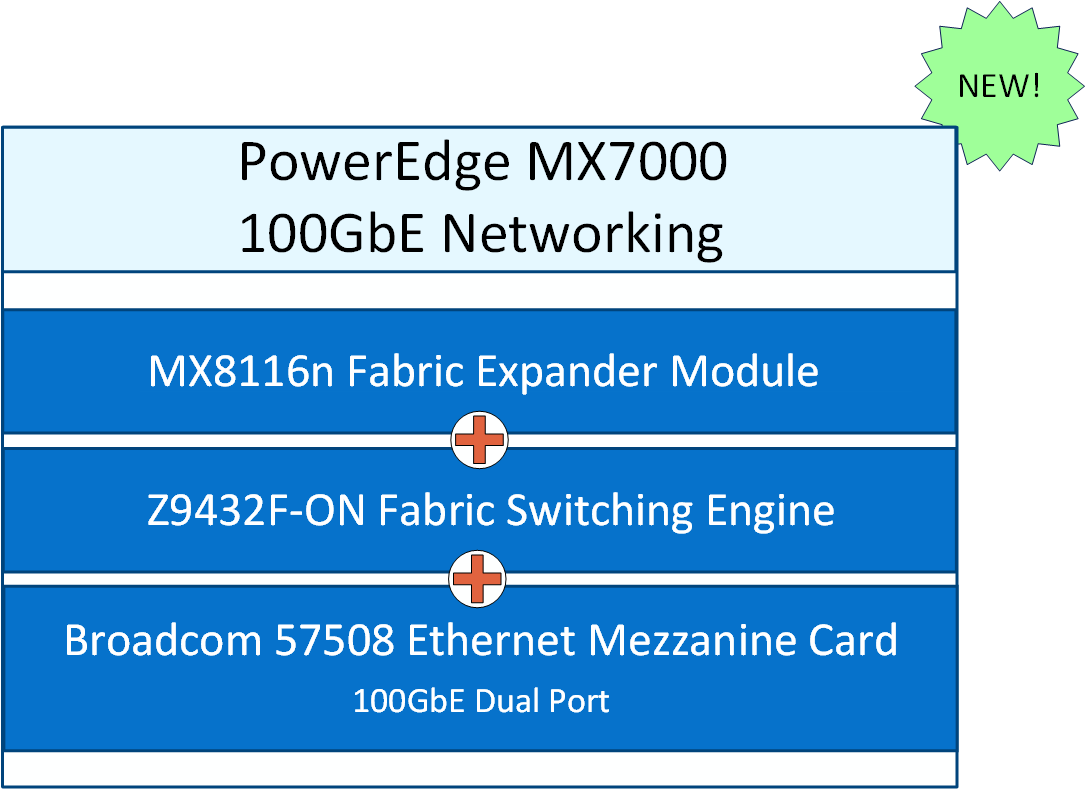
The MX8116n FEM can be installed in fabric A and B. Each 400GbE port connects to the Z9432F-ON FSE, supporting a single 100GbE connection for four compute sleds.
The MX Scalable Fabric Architecture allows the Z9432F-ON FSE to support up to a maximum of 14 MX7000 chassis and 112 MX compute sleds in a single fabric deployment. The Z9432F-ON FSE operates on Dell Networking SmartFabric OS10 in Full Switch mode only.
Here are some common deployment options for the 100GbE solution.
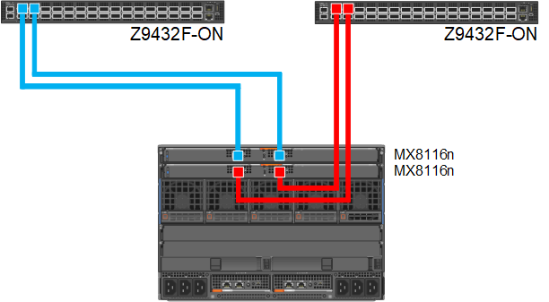
Figure 1. 100GbE single fabric deployment
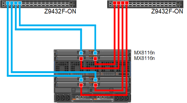
Figure 2. 100GbE dual fabric deployment
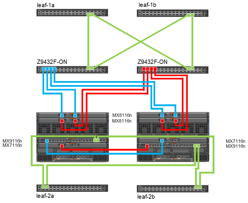
Figure 3. Combination MX8116n/Z9432F-ON and MX9116n/MX7116n deployment
For additional deployment options and detailed technical documentation on the new 100GbE networking solution see the updated Dell Technologies PowerEdge MX Networking Deployment Guide.
Another great source for hardware specifications, deployment diagrams, and cables/optics is the PowerEdge MX I/O Guide.
Related Blog Posts

MX8116n Fabric Expander Modular (FEM) port mapping with external Fabric Switching Engine (FSE)
Fri, 14 Jul 2023 13:16:33 -0000
|Read Time: 0 minutes
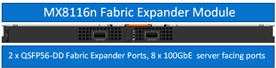
The Dell Networking MX8116n FEM acts as an Ethernet repeater, taking signals from an attached compute sled and repeating those signals to the associated lane on the external QSFP56-DD connector. The MX8116n FEM includes two QSFP56-DD interfaces, with each interface providing up to four 100 Gbps connections to the chassis and eight internal 100 GbE server facing ports.
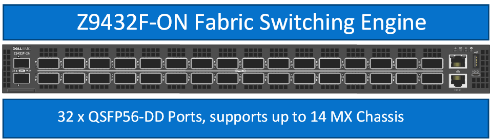
The Dell PowerSwitch Z9432F-ON fixed switch serves as the designated FSE of the MX platform and can support MX chassis deployed with 100 GbE or 25 GbE-based compute sleds. The switch comes equipped with 32 QSFP56-DD ports that provide uplinks, Virtual Link Trunking interconnect (VLTi), and fabric expansion connections.
The goal of this blog is to help you understand port-mapping information about MX8116n FEM, where the module is connected to NIC cards in compute sleds internally on one side and Fabric Switching Engine on the other side on external ports.
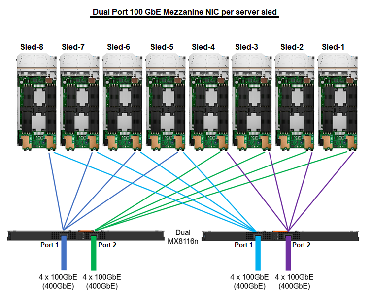
Figure 1. Port mapping of dual MX8116n FEM ports to NIC ports
Sled 1 through Sled 4 use Port 2 on the MX8116n, while Sled 5 through Sled 8 use Port 1.

Figure 2. MX8116n internal port mapping
The MX7000 chassis supports up to four MX8116n FEMs in Fabric A and Fabric B. Figure 3 shows one MX8116n FEM module that has two QSFP56-DD 400 GbE ports that can be split into 4x100 GbE to FSE facing ports and 8x100 GbE to facing internal sled NIC ports.
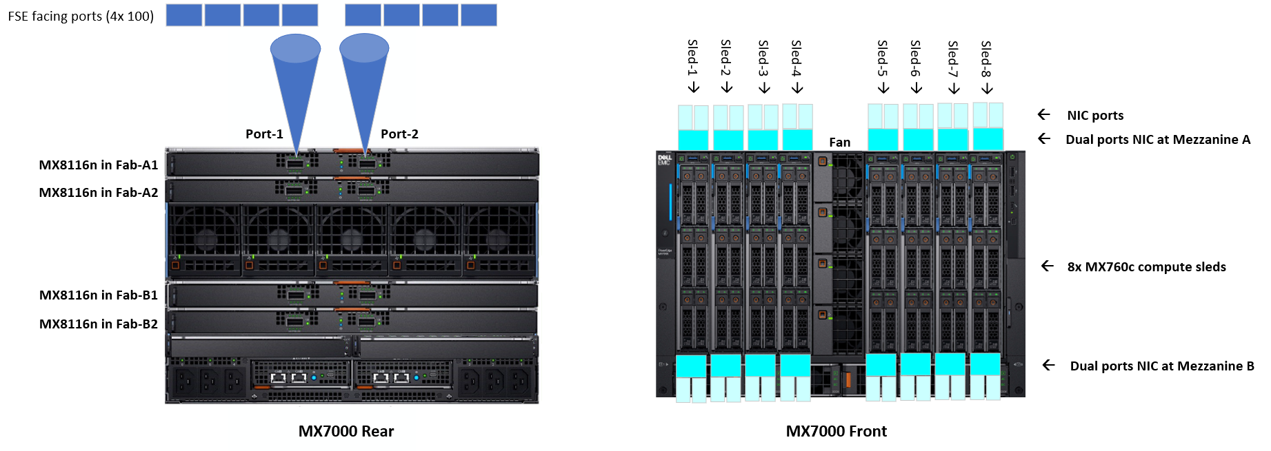
Figure 3. MX7000 chassis front and back physical view with IOMs and sleds port mapping
The MX8116n FEM can operate at 25 GbE and 100 GbE. The 25 GbE solution can support on both dual and quad port NICs, while the 100 GbE solution is supported on dual port NIC only. For the following examples in this blog, the PowerSwitch Z9432F-ON port mapping on 100 GbE dual port NIC using QSFP56-DD cables and 25 GbE dual port and quad port NICs using QSFP56-DD and QSFP28-DD.
The interfaces used on the Z9432F-ON are arbitrary. QSFP56-DD interfaces on the Z9432F-ON can be connected in any order.
Each port group in PowerSwitch Z9432F-ON contains two physical interfaces. The following examples shows the ports of the first port group 1/1/1 that contain interfaces 1/1/1-1/1/2 and the ports of the last port group 1/1/16 that contain interfaces 1/1/31-1/1/32. The port mode for each port interface can be configured in the port group configuration.
Compute sleds with 100 GbE dual port mezzanine cards
The following port group settings are required for 100 GbE dual port mezzanine cards for the Z9432F-ON:
port-group 1/1/1
profile unrestricted
port 1/1/1 mode Eth 100g-4x
port 1/1/2 mode Eth 100g-4x
port-group 1/1/16
profile unrestricted
port 1/1/31 mode Eth 100g-4x
port 1/1/32 mode Eth 100g-4x
Once the port modes are configured and the connections are made, the MX8116n ports auto negotiate to match the port operating mode of the Z9432F-ON interfaces. The internal servers facing ports of the MX8116n auto-negotiate with the mezzanine card port speed of 100 GbE.
Figure 4 shows the interface numbering for each sled and corresponding MX8116n port when using a QSFP56DD based optic or cable:
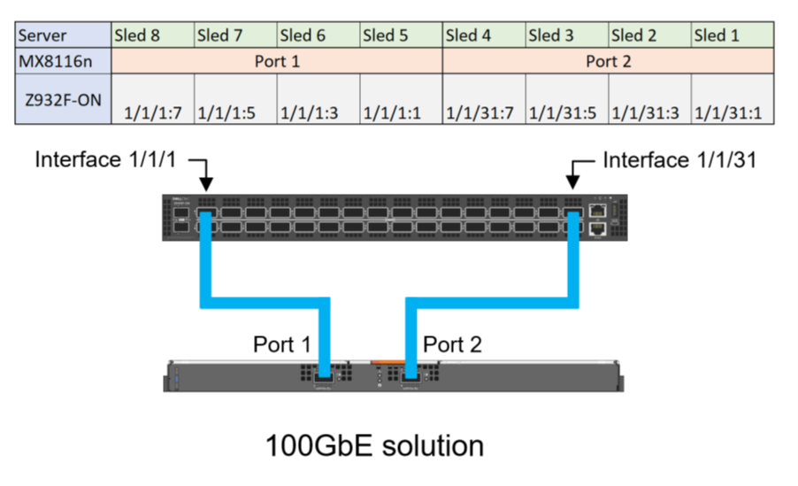
Figure 4. Z9432F-ON port mapping for 100 GbE solution
Compute sleds with 25 GbE quad port NIC using QSFP56-DD
The following port group settings are required for 25 GbE quad port NIC using QSFP56-DD on the Z9432F-ON:
- For the required 25g-8x port mode operation, the profile must first be set to restricted. This restriction means that the second port interface in the port group can only operate in a restricted mode.
- The restriction on the second port means that it must operate in a 1x mode, making the even ports unsuitable for connections to the MX8116n. Therefore, only the odd ports can be used for connections to the MX8116n.
port-group 1/1/1
profile restricted
port 1/1/1 mode Eth 25g-8x
port 1/1/2 mode Eth 400g-1x
port-group 1/1/16
profile restricted
port 1/1/31 mode Eth 25g-8x
port 1/1/32 mode Eth 400g-1x
Figure 5 shows the interface numbering for each sled and corresponding MX8116n port when using a QSFP56DD based optic or cable:
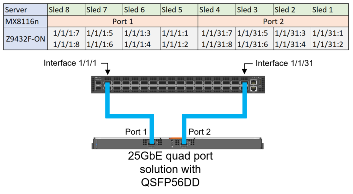
Figure 5. Z9432F-ON Port mapping for 25 GbE quad port solution for QSFP56DD based optics and cables
Compute sleds with 25 GbE quad port NIC using QSFP28-DD
The 25 GbE quad port NIC solution can use QSF28-DD based optics and cables. The following configuration shows the final state required for 25 GbE quad port NICs:
port-group 1/1/1
profile restricted
port 1/1/1 mode Eth 25g-8x
port 1/1/2 mode Eth 400g-1x
port-group 1/1/16
profile restricted
port 1/1/31 mode Eth 25g-8x
port 1/1/32 mode Eth 400g-1x
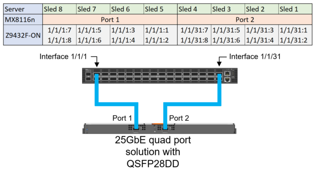
Figure 6. Z9432F-ON Port mapping for 25 GbE quad port solution with QSFP28-DD based optics and cables
Compute sleds with 25 GbE dual port NIC using QSFP56-DD
For the required 25g-4x port mode operation, the profile should stay in the default unrestricted setting. Unlike quad port deployments, dual port deployments can use both even and odd ports on the Z9432F-ON.
port-group 1/1/1
profile unrestricted
port 1/1/1 mode Eth 25g-8x
port 1/1/2 mode Eth 400g-1x
port-group 1/1/16
profile unrestricted
port 1/1/31 mode Eth 25g-8x
port 1/1/32 mode Eth 400g-1x
Figure 7 shows the interface numbering for each sled and corresponding MX8116n port when using a QSFP56DD based optic or cable:
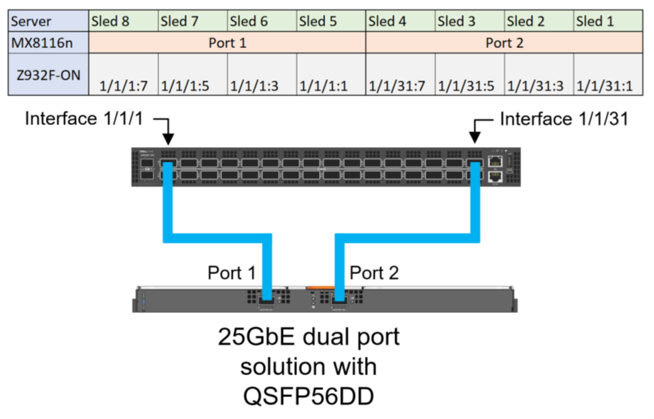
Figure 7. Z9432F-ON Port mapping for 25 GbE dual port solution for QSFP56DD based optic or cable
Compute sleds with 25 GbE dual port NIC using QSFP28-DD
The following configuration shows the final state required for 25 GbE dual port mezzanine cards, the profile should stay in the default unrestricted setting:
port-group 1/1/1
profile unrestricted
port 1/1/1 mode Eth 25g-4x
port 1/1/2 mode Eth 400g-1x
port-group 1/1/16
profile unrestricted
port 1/1/31 mode Eth 25g-4x
port 1/1/32 mode Eth 400g-1x
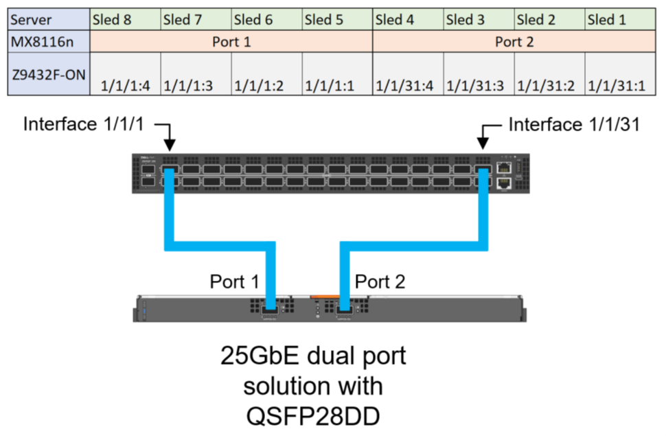
Figure 8. Z9432F-ON Port mapping for 25 GbE dual port solution with QSFP28-DD based optics and cables
References
Dell PowerEdge MX Networking Deployment Guide
Dell Technologies PowerEdge MX 100 GbE Solution with external FSE blog
Dell PowerEdge MX7000 Chassis User Guide

Dell Technologies PowerEdge MX with Cisco ACI Integration
Thu, 09 Feb 2023 20:05:01 -0000
|Read Time: 0 minutes
Introduction
This paper provides an example of integrating the Dell PowerEdge MX platform running Dell SmartFabric Services (SFS) with Cisco Application Centric Infrastructure (ACI).
The example in this blog assumes that the PowerEdge MX7000 chassis are configured in a Multi Chassis Management Group (MCM) and that you have a basic understanding of the PowerEdge MX platform.
As part of the PowerEdge MX platform, the SmartFabric OS10 network operating system includes SmartFabric Services, a network automation and orchestration solution that is fully integrated with the MX platform.
Configuration Requirements
Configuration of SmartFabric on PowerEdge MX with Cisco ACI makes the following assumptions:
- All MX7000 chassis and management modules are cabled correctly and in an MCM group.
- VLTi cables between MX Fabric Switching Engines (FSE) and Fabric Expander Modules (FEM) are connected correctly.
- PowerEdge and Cisco ACI platforms are in healthy status and are running updated software.
The example setup is validated using the following software versions:
- MX chassis: 2.00.00
- MX IOMs (MX9116n): 10.5.4.1.29
- Cisco APIC: 5.2(6e).
- Cisco leaf switches: 4.2(7u)
Refer to the Dell Networking Support and Interoperability Matrix for the latest validated versions.
Hardware and Logical Topology
The validated Cisco ACI environment includes a pair of Nexus C93180YC-EX switches as leafs. These switches are connected to a single Nexus C9336-PQ switch as the spine using 40GbE connections. MX9116n FSE switches are connected to the C93180YC-EX leafs using 100GbE cables.
The following section provides an overview of the topology and configuration steps. For detailed configuration instructions, refer to the Dell EMC PowerEdge MX SmartFabric and Cisco ACI Integration Guide.
Caution: The connection of an MX switch directly to the ACI spine is not supported.
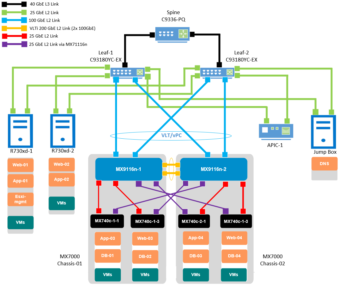
Figure 1 Validated SmartFabric and ACI environment logical topology
This blog is categorized into four major parts:
- Cisco Application Policy Infrastructure Controller (APIC)
- Dell PowerEdge MX OpenManage Enterprise-Modular (OME-M)
- VMware vCenter Server Appliance (VCSA)
- Dell OpenManage Network Integration (OMNI)
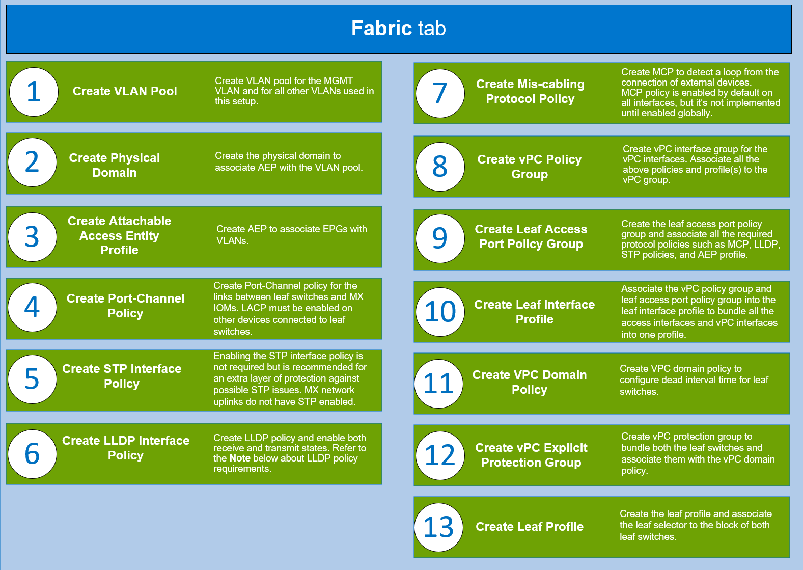
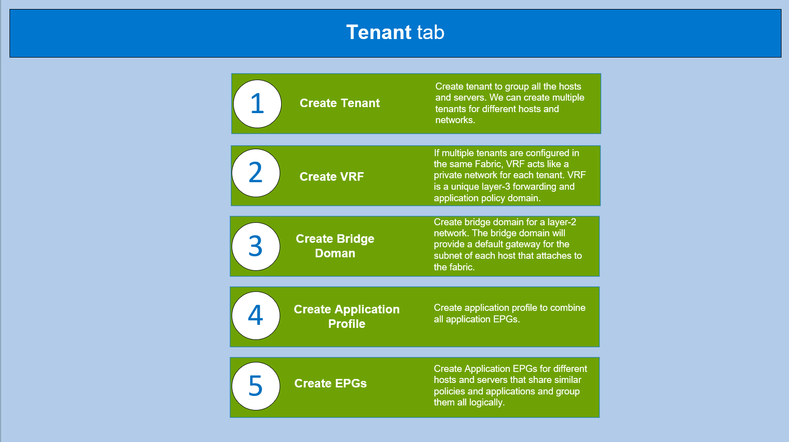
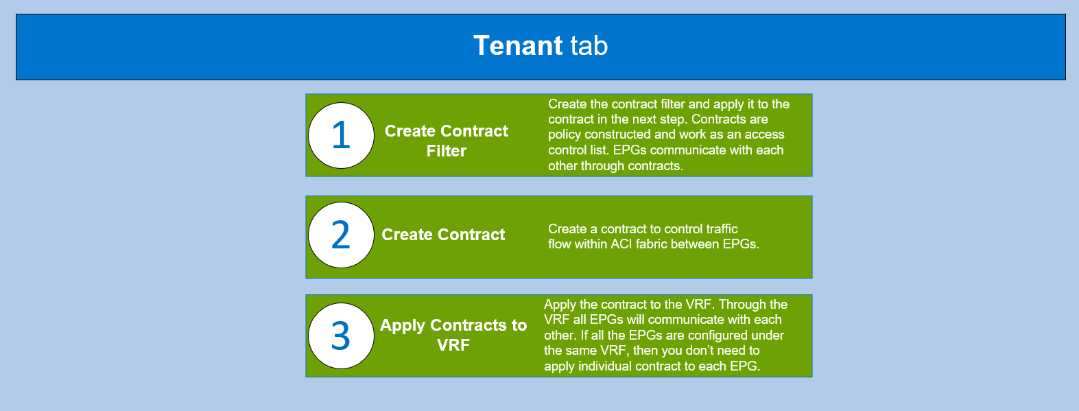
Cisco APIC
Cisco APIC provides a single point of automation and fabric element management in both virtual and physical environments. It helps the operators build fully automated and scalable multi-tenant networks.
To understand the required protocols, policies, and features that you must configure to set up the Cisco ACI, log in to the Cisco APIC controller and complete the steps shown in the following flowcharts.
CAUTION: Ensure all the required hardware is in place and all the connections are made as shown in the above logical topology.

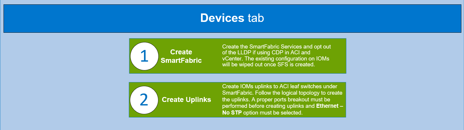
Note: If a storage area network protocol (such as FCoE) is configured, Dell Technologies suggest that you use CDP as a discovery protocol on ACI and vCenter, while LLDP remains disabled on the MX SmartFabric.
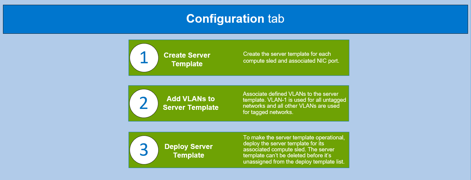
PowerEdge MX OME-M
The PowerEdge MX platform is a unified, high-performance data center infrastructure. It provides the agility, resiliency, and efficiency to optimize a wide variety of traditional and new, emerging data center workloads and applications. With its kinetic architecture and agile management, PowerEdge MX dynamically configures compute, storage, and fabric; increases team effectiveness; and accelerates operations. The responsive design delivers the innovation and longevity that customers need for their IT and digital business transformations.


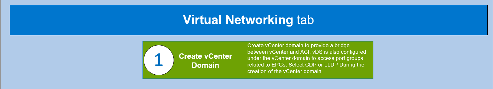
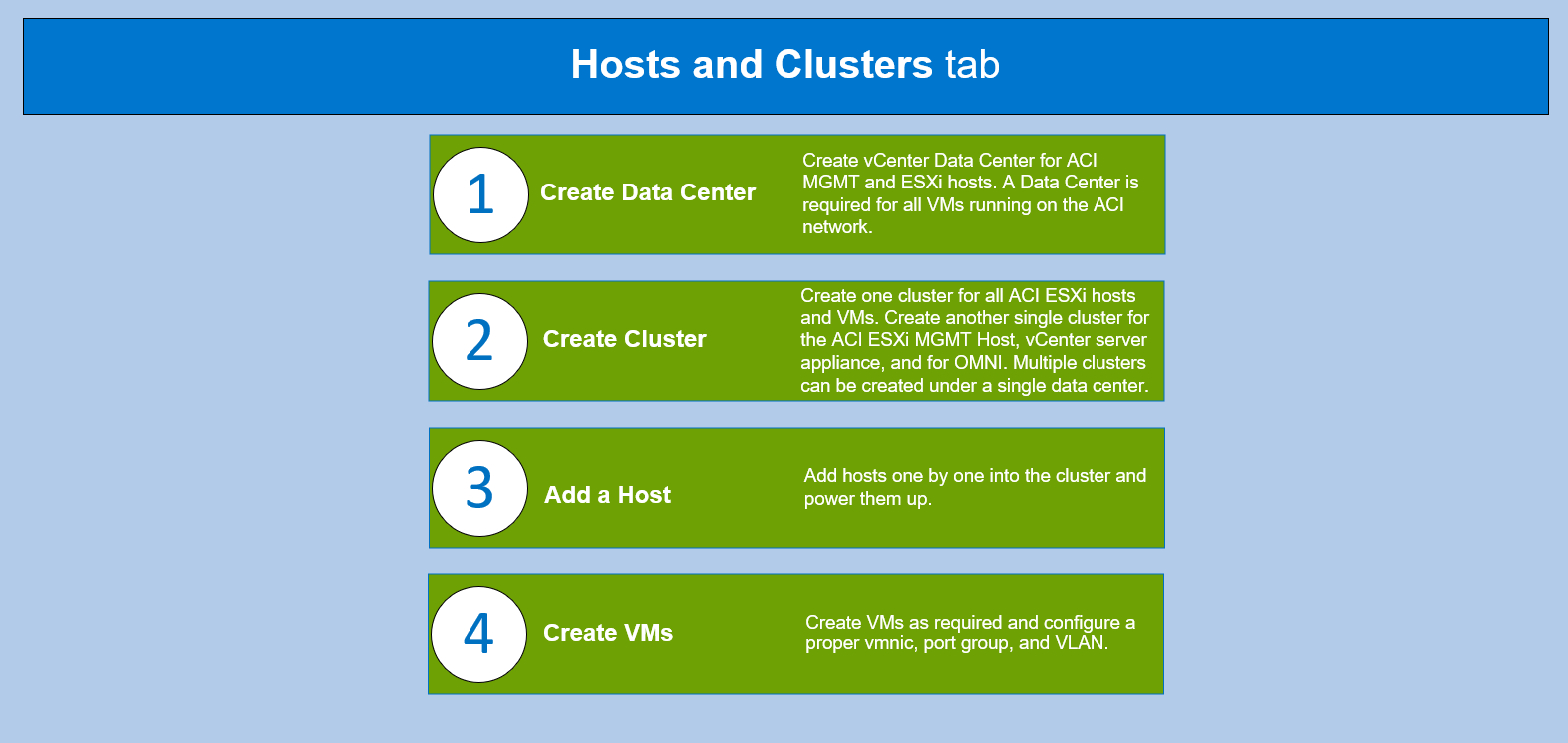
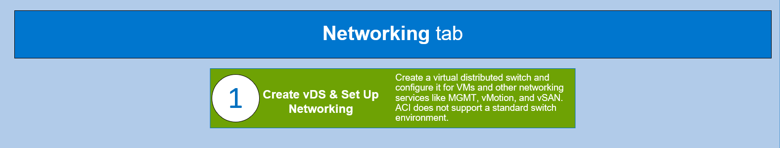
VMware vCenter
VMware vCenter is an advanced management centralized platform application. The flowchart below assumes that you have completed the following prerequisites:
- Install the vCenter server appliance on the ESXi MGMT server.
- Install the ESXi VMvisor on the ESXi host servers for the MX SmartFabric and Cisco ACI integration environment.
OMNI
OMNI is an external plug-in for VMware vCenter that is designed to complement SFS by integrating with VMware vCenter to perform fabric automation. This integration automates VLAN changes that occur in VMware vCenter and propagates those changes into the related SFS instances running on the MX platform, as shown in the following flowchart figure.
The combination of OMNI and Cisco ACI vCenter integration creates a fully automated solution. OMNI and the Cisco APIC recognize and allow a VLAN change to be made in vCenter, and this change will flow through the entire solution without any manual intervention.
For more information about OMNI, see the SmartFabric Services for OpenManage Network Integration User Guide on the Dell EMC OpenManage Network Integration for VMware vCenter documentation page.
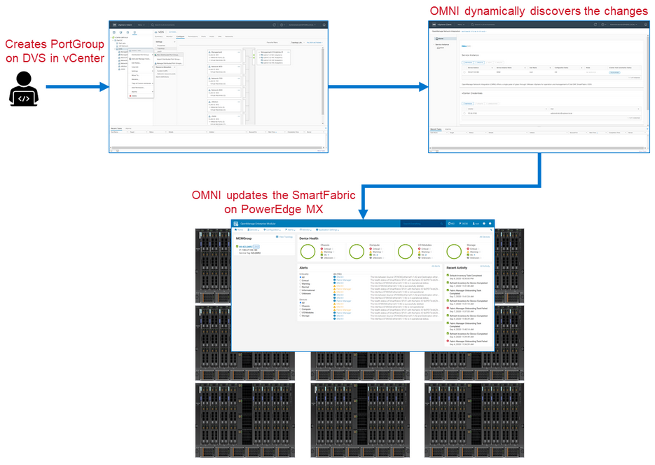
Figure 2 OMNI integration workflow
MX Single Chassis Deployment for ACI Integration
A single MX7000 chassis may also join an existing Cisco ACI environment by using the MX5108n ethernet switch. The MX chassis in this example has two MX5108n ethernet switches and two MX compute sleds.
The connections between the ACI environment and the MX chassis are made using a double-sided multi-chassis link aggregation group (MLAG). The MLAG is called a vPC on the Cisco ACI side and a VLT on the PowerEdge MX side. The following figure shows the environment.
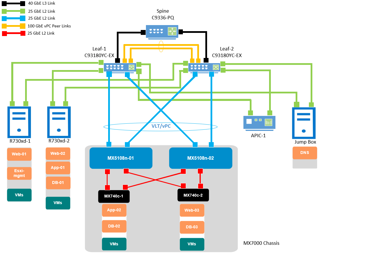
Figure 3 SmartFabric and ACI environment using MX5108n Ethernet switches logical topology
Reference
List of Acronyms
ACI: Cisco Application Centric Infrastructure (ACI) AEP: Attachable Access Entity Profile APIC: Cisco Application Policy Infrastructure Controller CDP: Cisco Discovery Protocol EPG: End Point Groups LLDP: Link Local Discovery Protocol MCP: Mis-Cabling Protocol MCM: Multi Chassis Management Group MLAG: Multi-chassis link aggregation group MX FSE: Dell MX Fabric Switching Engines MX FEM: Dell MX Fabric Expander Modules MX IOMs: Dell MX I/O Modules | MX MCM: Dell MX Multichassis Management Group OME-M: Dell OpenManage Enterprise-Modular OMNI: Dell OpenManage Network Integration PC: Port Channel STP: Spanning Tree Protocol VCSA: VMware vCenter Server Appliance vDS: Virtual Distributed Switch VLAN: Virtual Local Area Network VM: virtual machine VMM: VMware Virtual Machine Manager vPC: Virtual Port Channel VRF: Virtual Routing Forwarding |
Documentation and Support
Dell EMC PowerEdge MX Networking Deployment Guide
Dell EMC PowerEdge MX SmartFabric and Cisco ACI Integration Guide.
Networking Support & Interoperability Matrix
Dell EMC PowerEdge MX VMware ESXi with SmartFabric Services Deployment Guide