In this deployment example, the uplink is required for the VxRail nodes to access the DNS & NTP services. Uplinks to the existing network may be configured as Layer 2, Layer 3 routed, or Layer 3 VLAN. This section covers Layer 2 uplinks.
The switches are cabled as shown in the figure below. When Layer 2 uplink configuration is complete, Leaf1A and Leaf1B connect with a VLT port channel to the external switch pair. In this example, an existing DNS/NTP server also connects to the external switches using a VLT port channel. All VLT port channels use LACP in this guide. All ports on the four switches that are shown in the following figure are in the External Management VLAN, 1811.
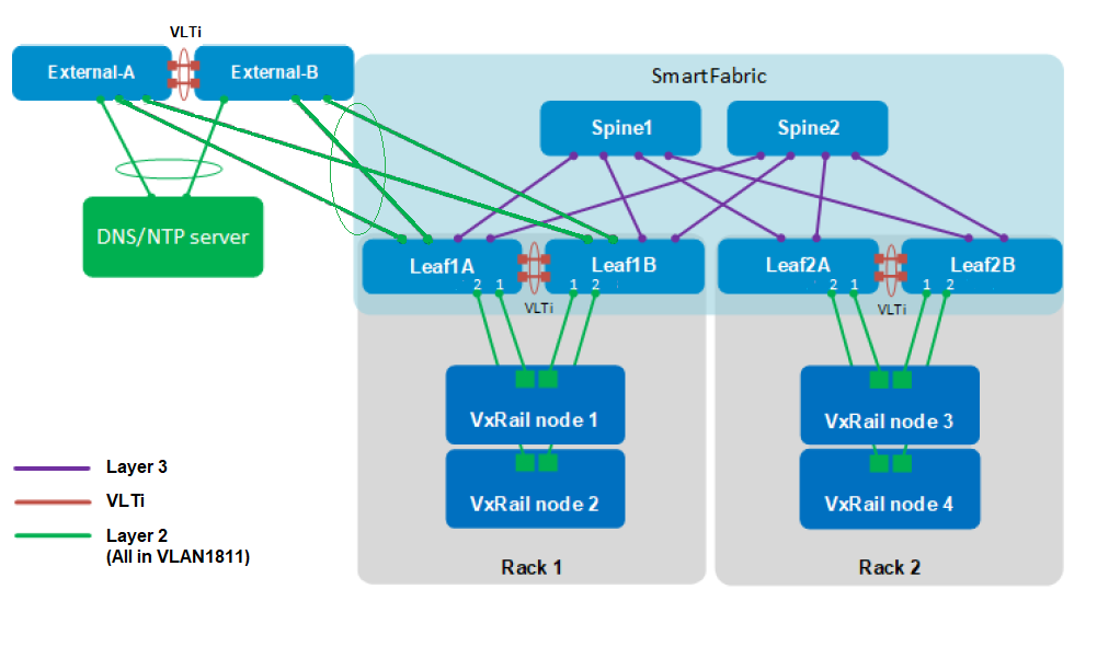
Any ports available on the leaf switches may be used as uplinks, provided they are compatible with the corresponding ports on the external switches.
To configure Layer 2 uplinks to the external network, perform the following steps:
- In the SFS UI, select the Uplink tab.
- Under Uplink, click +CREATE
Figure 34. SFS UI Uplink tab 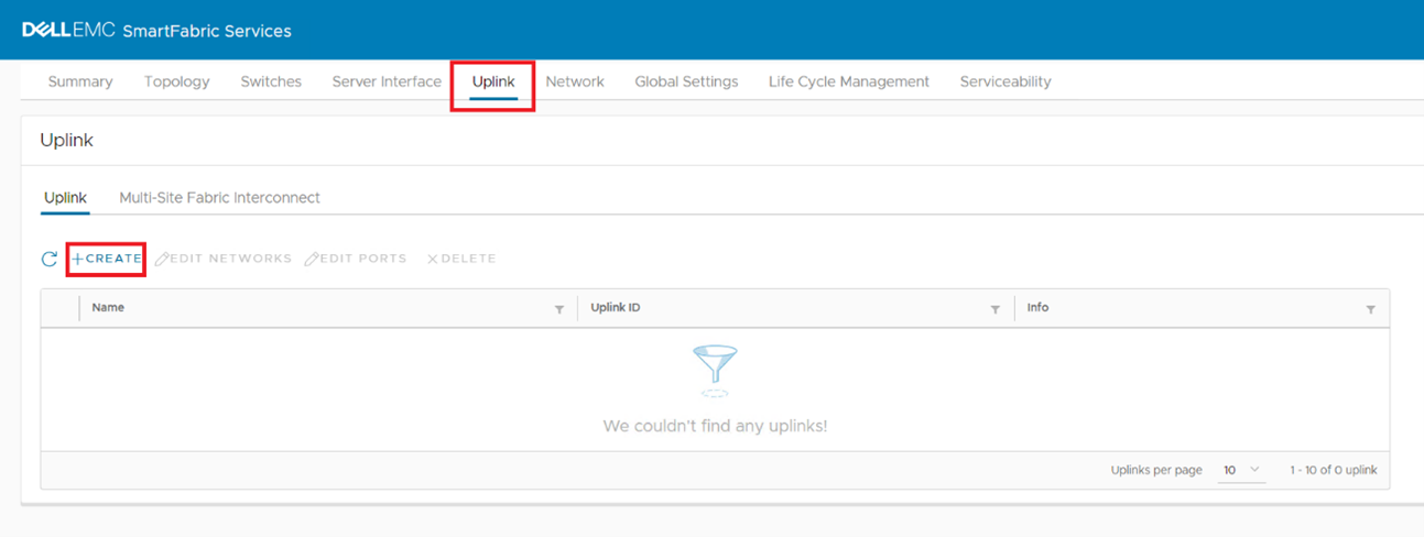
- On the Uplink Details page:
- Set Uplink Port Type to L2.
- Enter a Name (required) and Description (optional).
Figure 35. Uplink Details page 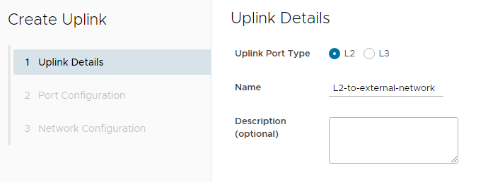
- Click NEXT.
- On the Port Configuration page:
- Next to Select Rack to Create Uplink on, select the rack that contains the switches with the uplinks. In this example, Rack 1 is selected.
- Under each leaf, select the interface or interfaces that you will use for the uplink. In this example, 100 GbE interfaces 1/1/53 and 1/1/54 are selected on each leaf. The Port Channel mode is kept at its default setting, LACP. Note: Be sure to configure the corresponding ports on the external switches with the same port channel mode. External switch configuration examples using LACP are provided in the Configure external switches for L2 connections section of this guide.
Figure 36. Port Configuration page 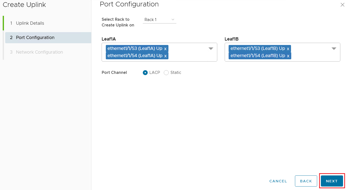
- Click NEXT.
- In the Network Selection box, select the External Management VLAN created earlier, extmgmt (VLAN-1811). This makes the uplinks the tagged members of the External Management VLAN. Note: In this example, an untagged network is not selected.
- If networks automatically created through vCenter integration are to be extended on this uplink, select Yes. Otherwise, select No (default). No is used in this example. Note: Networks created through vCenter integration refers to networks that are created in vCenter that are automatically configured on the SmartFabric switches by OMNI.
Figure 37. Network configuration 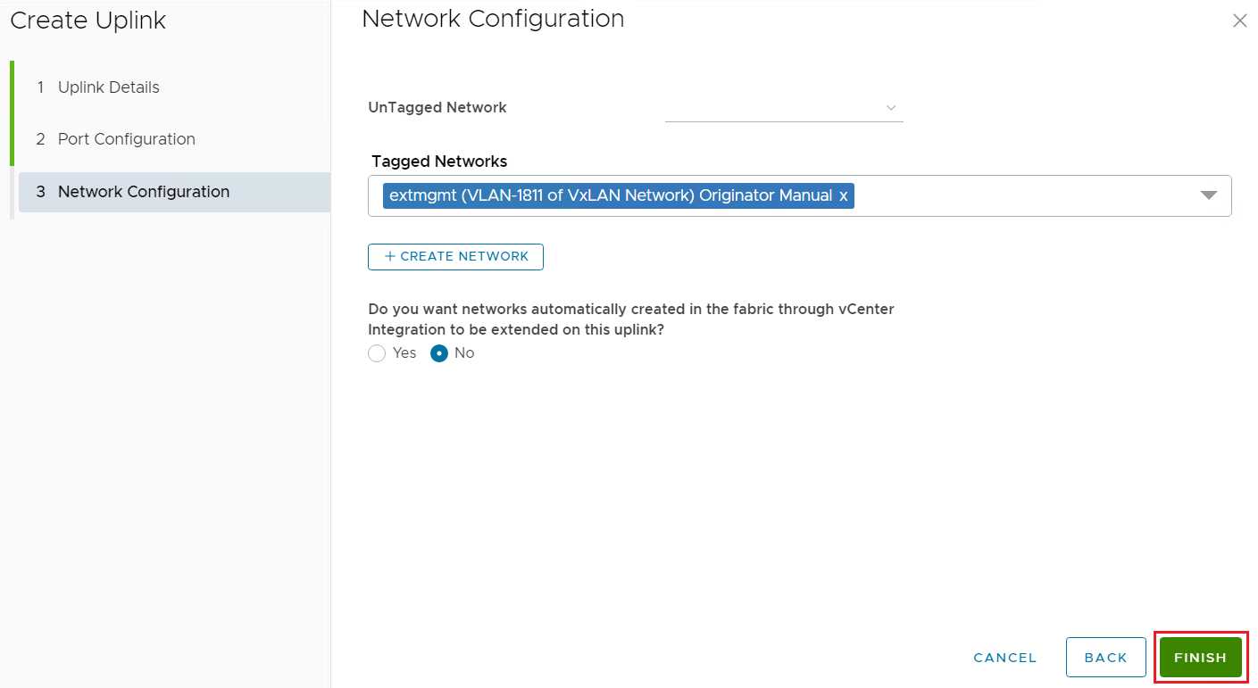
- Click FINISH to apply the settings. After configuration, the uplink is listed on the Uplink page of the SFS UI, along with a series of Success messages. Note: You may need to click the blue Refresh icon for the uplink to display.
Figure 38. Uplink page after L2 uplink is configured 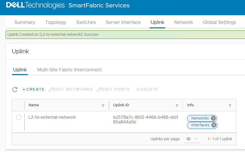
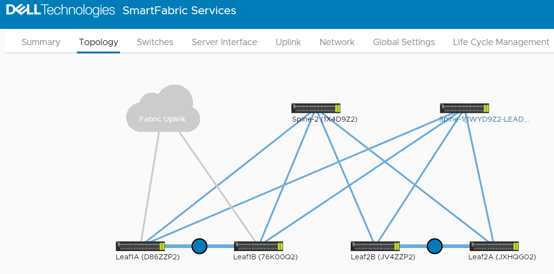
- Click the Topology tab. The uplink connections are added to the topology as shown in the following figure.
Figure 39. Topology with L2 uplink created