

Assets

Dell PowerStore: vVol Replication with PowerCLI
Wed, 14 Jun 2023 14:57:44 -0000
|Read Time: 0 minutes
Overview
In PowerStoreOS 2.0, we introduced asynchronous replication of vVol-based VMs. In addition to using VMware SRM to manage and control the replication of vVol-based VMs, you can also use VMware PowerCLI to replicate vVols. This blog shows you how.
To protect vVol-based VMs, the replication leverages vSphere storage policies for datastores. Placing VMs in a vVol storage container with a vSphere storage policy creates a replication group. The solution uses VASA 3.0 storage provider configurations in vSphere to control the replication of all individual configuration-, swap-, and data vVols in a vSphere replication group on PowerStore. All vVols in a vSphere replication group are managed in a single PowerStore replication session.
Requirements for PowerStore asynchronous vVol replication with PowerCLI:
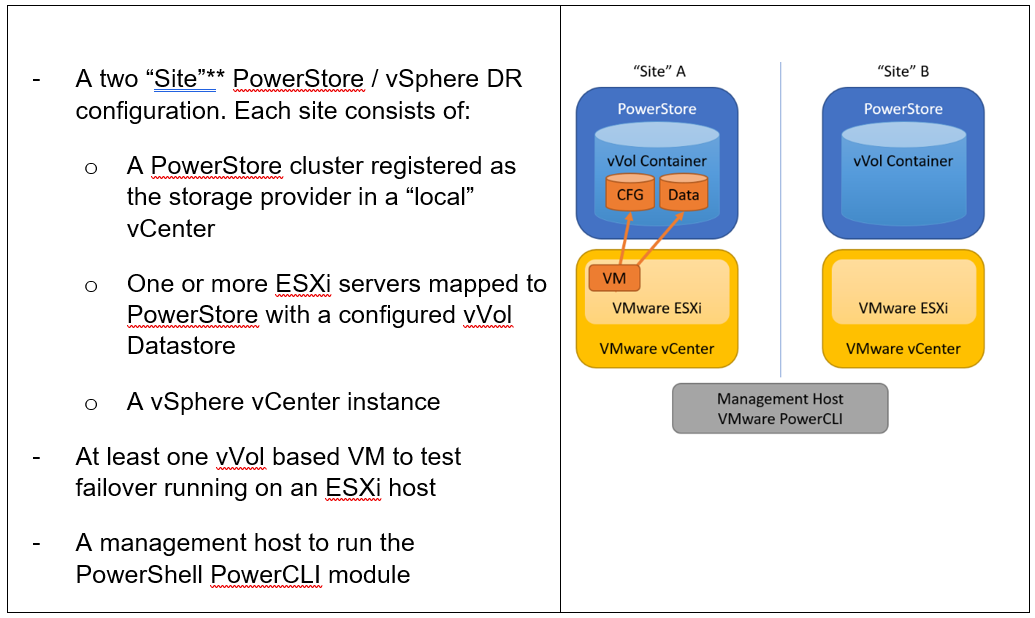
**As in VMware SRM, I’m using the term “site” to differentiate between primary and DR installation. However,
depending on the use case, all systems could also be located at a single location.
Let’s start with some terminology used in this blog.
PowerStore cluster | A configured PowerStore system that consists of one to four PowerStore appliances. |
PowerStore appliance | A single PowerStore entity that comes with two nodes (node A and node B). |
PowerStore Remote Systems (pair) | Definition of a relationship of two PowerStore clusters, used for replication. |
PowerStore Replication Rule | A replication configuration used in policies to run asynchronous replication. The rule provides information about the remote systems pair and the targeted recovery point objective time (RPO). |
PowerStore Replication Session | One or more storage objects configured with a protection policy that include a replication rule. The replication session controls and manages the replication based on the replication rule configuration. |
VMware vSphere VM Storage Policy | A policy to configure the required characteristics for a VM storage object in vSphere. For vVol replication with PowerStore, the storage policy leverages the PowerStore replication rule to set up and manage the PowerStore replication session. A vVol-based VM consists of a config vVol, swap vVol, and one or more data vVols. |
VMware vSphere Replication Group | In vSphere, the replication is controlled in a replication group. For vVol replication, a replication group includes one or more vVols. The granularity for failover operations in vSphere is replication group. A replication group uses a single PowerStore replication session for all vVols in that replication group. |
VMware Site Recovery Manager (SRM) | A tool that automates failover from a production site to a DR site. |
Preparing for replication
For preparation, similar to VMware SRM, there are some steps required for replicated vVol-based VMs:
Note: When frequently switching between vSphere and PowerStore, an item may not be available as expected. In this case, a manual synchronization of the storage provider in vCenter might be required to make the item immediately available. Otherwise, you must wait for the next automatic synchronization.
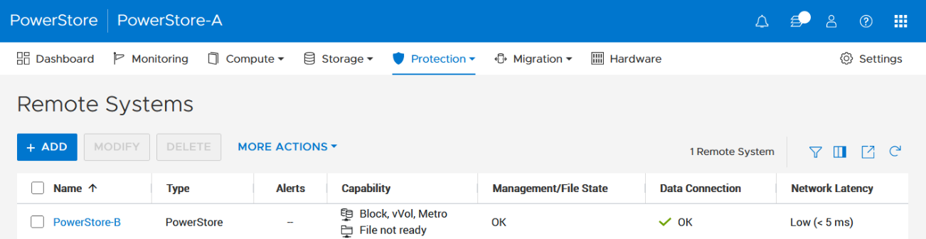
- Using the PowerStore UI, set up a remote system relationship between participating PowerStore clusters. It’s only necessary to perform this configuration on one PowerStore system. When a remote system relationship is established, it can be used by both PowerStore systems.
Select Protection > Remote Systems > Add remote system.
When there is only a single storage container on each PowerStore in a remote system relationship, PowerStoreOS also creates the container protection pairing required for vVol replication.
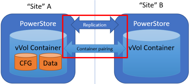
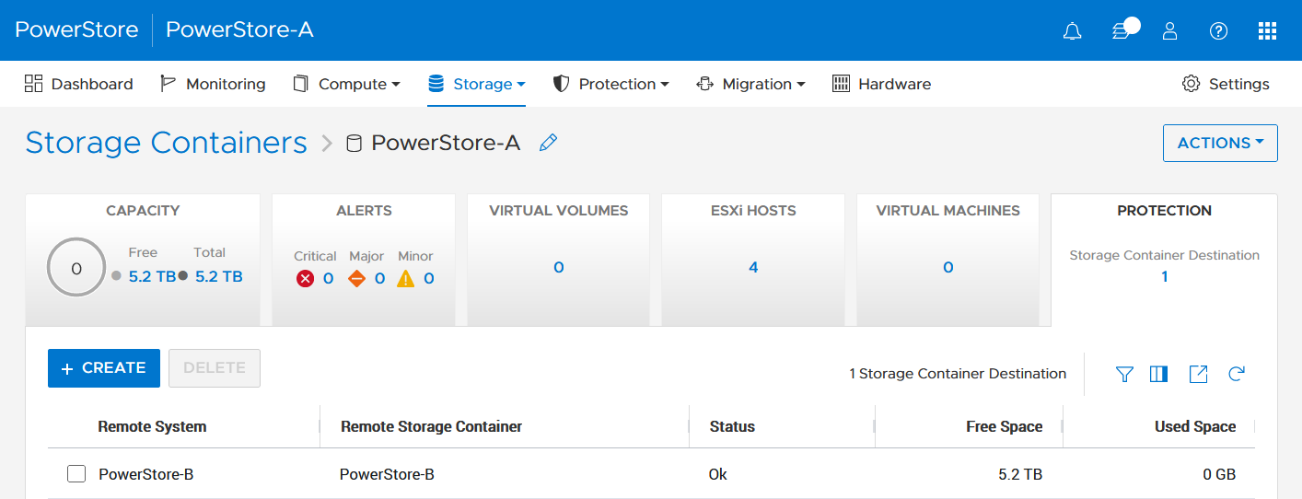
To check the configuration or create storage container protection pairing when more storage containers are configured, select Storage > Storage Containers > [Storage Container Name] > Protection.
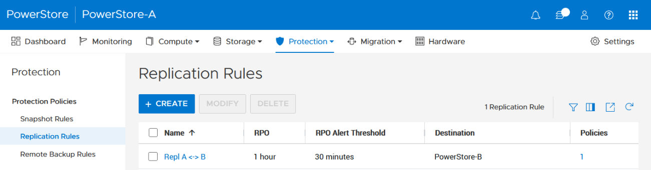
2. The VMware Storage Policy (which is created in a later step) requires existing replication rules on both PowerStoresystems, ideally with same characteristics. For this example, the replication rule replicates from PowerStore-A to PowerStore-B with a RPO of one hour, and 30 minutes for the RPO Alert Threshold.
Select Protection > Protection Policies > Replication Rules.
3. As mentioned in the Overview, VASA 3.0 is used for the communication between PowerStore and vSphere. If not configured already, register the local PowerStore in both vCenters as the storage provider in the corresponding vSphere vCenter instance.
In the vSphere Client, select [vCenter server] > Configuration > Storage Providers.
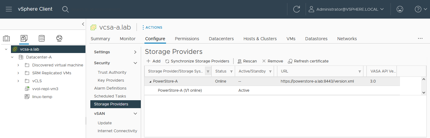
Use https://<PowerStore>:8443/version.xml as the URL with the PowerStore user and password to register the PowerStore cluster.
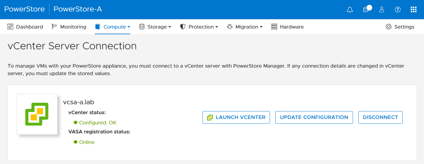
Alternatively, use PowerStore for a bidirectional registration. When vCenter is registered in PowerStore, PowerStoreOS gets more insight about running VMs for that vCenter. However, in the current release, PowerStoreOS can only handle a single vCenter connection for VM lookups. When PowerStore is used by more than one vCenter, it’s still possible to register a PowerStore in a second vCenter as the storage provider, as mentioned before.
In the PowerStore UI, select Compute > vCenter Server Connection.
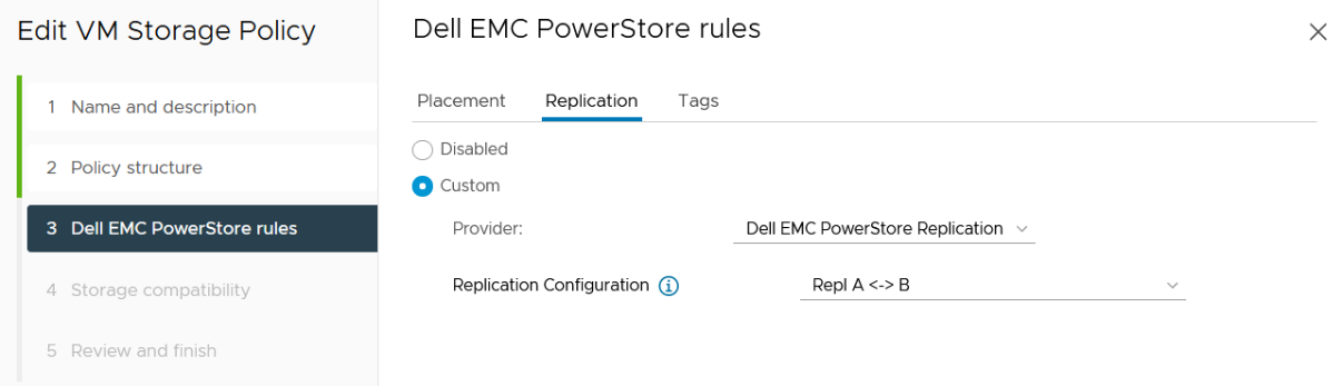
4. Set up a VMware storage policy with a PowerStore replication rule on both vCenters.
The example script in the section section Using PowerCLI and on myScripts4u@github requires the same Storage Policy name for both vCenters.
In the vSphere Client, select Policies and Profiles > VM Storage Policies > Create.
Enable “Dell EMC PowerStore” storage for datastore specific rules:
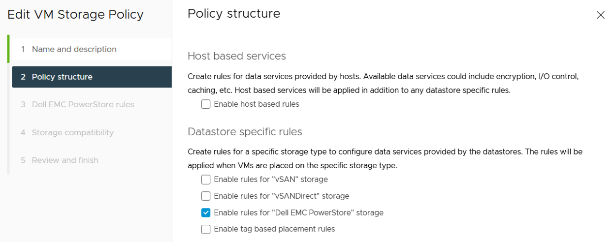
then choose the PowerStore replication rule:
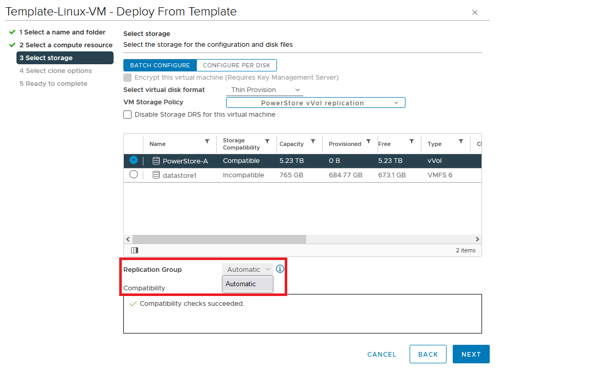
5. Create a VM on a vVol storage container and assign the storage protection policy with replication.
When a storage policy with replication is set up for a VM, you must specify a replication group. Selecting “automatic” creates a replication group with the name of the VM. Multiple VMs can be protected in one replication group.
When deploying another VM on the same vVol datastore, the name of the other replicated VM appears in the list for the Replication Group.
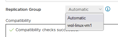
All vVol replication operations are on a Replication Group granularity. For instance, it’s not possible to failover only a single VM of a replication group.
That’s it for the preparation! Let’s continue with PowerCLI.
Using PowerCLI
Disclaimer: The PowerShell snippets shown below are developed only for educational purposes and provided only as examples. Dell Technologies and the blog author do not guarantee that this code works in your environment or can provide support in running the snippets.
To get the required PowerStore modules for PowerCLI, start PowerShell or PowerShell ISE and use Install-Module to install VMware.PowerCLI:
PS C:\> Install-Module -Name VMware.PowerCLI
The following example uses the replication group “vvol-repl-vm1”, which includes the virtual machines “vvol-repl-vm1” and “vvol-repl-vm2”. Because a replication group name might not be consistent with a VM to failover, the script uses the virtual machine name “vvol-repl-vm2” to get the replication group for failover.
Failover
This section shows an example failover of a vVol-based VM “vvol-vm2” from a source vCenter to a target vCenter.
1. Load modules, allow PowerStore to connect to multiple vCenter instances, and set variables for the VM, vCenters, and vCenter credentials. The last two commands in this step establishes the connection to both vCenters.
Import-Module VMware.VimAutomation.Core
Import-Module VMware.VimAutomation.Common
Import-Module VMware.VimAutomation.Storage
Set-PowerCLIConfiguration -DefaultVIServerMode 'Multiple' -Scope ([VMware.VimAutomation.ViCore.Types.V1.ConfigurationScope]::Session) -Confirm:$false  | Out-Null
$virtualmachine = "vvol-vm2"                   # Enter VM name of a vVol VM which should failover
$vcUser = 'administrator@vsphere.local'        # Change this to your VC username
$vcPass = 'xxxxxxxxxx'                         # VC password
$siteA = "vcsa-a.lab"                          # first vCenter
$siteB = "vcsa-b.lab"                          # second vCenter
Connect-VIServer -User "$vcUser" -Password "$vcPass" -Server $siteA -WarningAction SilentlyContinue
Connect-VIServer -User "$vcUser" -Password "$vcPass" -Server $siteB -WarningAction SilentlyContinue
2. Get replication group ($rg), replication group pair ($rgPair), and storage policy ($stoPol) for the VM. Because a replication group may have additional VMs, all VMs in the replication group are stored in $rgVMs.
$vm = get-vm $virtualmachine
# find source vCenter – this allows the script to failover (Site-A -> Site-B) and failback (Site-B -> Site-A)
$srcvCenter=$vm.Uid.Split(":")[0].Split("@")[1]
if ( $srcvCenter -like $siteA ) {
     $siteSRC=$siteA
     $siteDST=$siteB
} else {
     $siteSRC=$siteB
    $siteDST=$siteA
}
$rg = get-spbmreplicationgroup -server $siteSRC -VM $vm
$rgPair = Get-SpbmReplicationPair -Source $rg
$rgVMs=(Get-SpbmReplicationGroup -server $siteSRC -Name $rg| get-vm)
$stoPol = ( $vm | Get-SpbmEntityConfiguration).StoragePolicy.Name
3. Try a graceful shutdown of VMs in $rgVMs and wait ten seconds. Shut down VMs after three attempts.
$rgVMs | ForEach-Object {
     if ( (get-vm $_).PowerState -eq "PoweredOn")
     {
         stop-vmguest -VM $_ -confirm:$false -ErrorAction silentlycontinue | Out-Null
         start-sleep -Seconds 10
         $cnt=1
         while ((get-vm $_).PowerState -eq "PoweredOn" -AND $cnt -le 3 ) {
            Start-Sleep -Seconds 10
            $cnt++
         }
         if ((get-vm $_).PowerState -eq "PoweredOn") {
            stop-vm $_ -Confirm:$false  | Out-Null
         }
     }
}
4. It’s now possible to prepare and execute the failover. At the end, $vmxfile contains the vmx files that are required to register the VMs at the destination. During failover, a final synchronize before doing the failover ensures that all changes are replicated to the destination PowerStore. When the failover is completed, the vVols at the failover destination are available for further steps.
$syncRg = Sync-SpbmReplicationGroup -PointInTimeReplicaName "prePrepSync" -ReplicationGroup $rgpair.target
$prepareFailover = start-spbmreplicationpreparefailover $rgPair.Source -Confirm:$false -RunAsync
Wait-Task $prepareFailover
$startFailover = Start-SpbmReplicationFailover $rgPair.Target -Confirm:$false -RunAsync
$vmxfile = Wait-Task $startFailover
5. For clean up on the failover source vCenter, we remove the failed over VM registrations. On the failover target, we search for a host ($vmhostDST) and register, start, and set the vSphere Policy on VMs. The array @newDstVMs will contain VM information at the destination for the final step.
$rgvms | ForEach-Object {
     $_ | Remove-VM -ErrorAction SilentlyContinue -Confirm:$false
}
$vmhostDST = get-vmhost -Server $siteDST | select -First 1
$newDstVMs= @()
$vmxfile | ForEach-Object {
     $newVM = New-VM -VMFilePath $_ -VMHost $vmhostDST
     $newDstVMs += $newVM
}
$newDstVms | forEach-object {
     $vmtask = start-vm $_ -ErrorAction SilentlyContinue -Confirm:$false -RunAsync
     wait-task $vmtask -ErrorAction SilentlyContinue | out-null
     $_ | Get-VMQuestion | Set-VMQuestion -Option ‘button.uuid.movedTheVM’ -Confirm:$false

     $hdds = Get-HardDisk -VM $_ -Server $siteDST
     Set-SpbmEntityConfiguration -Configuration $_ -StoragePolicy $stopol -ReplicationGroup  $rgPair.Target | out-null
     Set-SpbmEntityConfiguration -Configuration $hdds -StoragePolicy $stopol -ReplicationGroup  $rgPair.Target | out-null
}
6. The final step enables the protection from new source.
start-spbmreplicationreverse $rgPair.Target  | Out-Null
$newDstVMs  | foreach-object {
    Get-SpbmEntityConfiguration -HardDisk $hdds -VM $_ | format-table -AutoSize
}
Additional operations
Other operations for the VMs are test-failover and an unplanned failover on the destination. The test failover uses the last synchronized vVols on the destination system and allows us to register and run the VMs there. The vVols on the replication destination where the test is running are not changed. All changes are stored in a snapshot. The writeable snapshot is deleted when the test failover is stopped.
Test failover
For a test failover, follow Step 1 through Step 3 from the failover example and continue with the test failover. Again, $vmxfile contains VMX information for registering the test VMs at the replication destination.
$sync=Sync-SpbmReplicationGroup -PointInTimeReplicaName "test" -ReplicationGroup $rgpair.target
$prepareFailover = start-spbmreplicationpreparefailover $rgPair.Source -Confirm:$false -RunAsync
$startFailover = Start-SpbmReplicationTestFailover $rgPair.Target -Confirm:$false -RunAsync
$vmxfile = Wait-Task $startFailover
It’s now possible to register the test VMs. To avoid IP network conflicts, disable the NICs, as shown here.
$newDstVMs= @()
$vmhostDST = get-vmhost -Server $siteDST | select -First 1
$vmxfile | ForEach-Object {
    write-host $_
    $newVM = New-VM -VMFilePath $_ -VMHost $vmhostDST
    $newDstVMs += $newVM
}
$newDstVms | forEach-object {
    get-vm -name $_.name -server $siteSRC | Start-VM -Confirm:$false -RunAsync | out-null # Start VM on Source
    $vmtask = start-vm $_ -server $siteDST -ErrorAction SilentlyContinue -Confirm:$false -RunAsync
    wait-task $vmtask -ErrorAction SilentlyContinue | out-null
    $_ | Get-VMQuestion | Set-VMQuestion -Option ‘button.uuid.movedTheVM’ -Confirm:$false
    while ((get-vm -name $_.name -server $siteDST).PowerState -eq "PoweredOff" ) {
        Start-Sleep -Seconds 5
    }
    $_ | get-networkadapter | Set-NetworkAdapter -server $siteDST -connected:$false -StartConnected:$false -Confirm:$false
}
After stopping and deleting the test VMs at the replication destination, use stop-SpbmReplicationFailoverTest to stop the failover test. In a new PowerShell or PowerCLI session, perform Steps 1 and 2 from the failover section to prepare the environment, then continue with the following commands.
$newDstVMs | foreach-object {
    stop-vm -Confirm:$false $_
    remove-vm -Confirm:$false $_
}
Stop-SpbmReplicationTestFailover $rgpair.target
Unplanned failover
For an unplanned failover, the cmdlet Start-SpbmReplicationFailover provides the option -unplanned which can be executed against a replication group on the replication destination for immediate failover in case of a DR. Because each infrastructure and DR scenario is different, I only show the way to run the unplanned failover of a single replication group in case of a DR situation.
To run an unplanned failover, the script requires the replication target group in $RgTarget. The group pair information is only available when connected to both vCenters. To get a mapping of replication groups, use Step 1 from the Failover section and execute the Get-SpbmReplicationPair cmdlet:
PS> Get-SpbmReplicationPair | Format-Table -autosize
Source Group Target Group
------------ ------------
vm1          c6c66ee6-e69b-4d3d-b5f2-7d0658a82292
The following part shows how to execute an unplanned failover for a known replication group. The example connects to the DR vCenter and uses the replication group id as an identifier for the unplanned failover. After the failover is executed, the script registers the VMX in vCenter to bring the VMs online.
Import-Module VMware.VimAutomation.Core
Import-Module VMware.VimAutomation.Common
Import-Module VMware.VimAutomation.Storage
$vcUser = 'administrator@vsphere.local'                # Change this to your VC username
$vcPass = 'xxxxxxxxxx'                                 # VC password
$siteDR = "vcsa-b.lab"                                 # DR vCenter
$RgTarget = "c6c66ee6-e69b-4d3d-b5f2-7d0658a82292"     # Replication Group Target – required from replication Source before running the unplanned failover
                                                       # to get the information run get-SpbmReplicationPair | froamt-table -autosize when connected to both vCenter
Connect-VIServer -User "$vcUser" -Password "$vcPass" -Server $siteDR -WarningAction SilentlyContinue
# initiate the failover and preserve vmxfiles in $vmxfile
$vmxfile = Start-SpbmReplicationFailover -server $siteDR -Unplanned -ReplicationGroup $RgTarget
$newDstVMs= @()
$vmhostDST = get-vmhost -Server $siteDR | select -First 1
$vmxfile | ForEach-Object {
    write-host $_
    $newVM = New-VM -VMFilePath $_ -VMHost $vmhostDST
    $newDstVMs += $newVM
}
$newDstVms | forEach-object {
    $vmtask = start-vm $_ -server $siteDST -ErrorAction SilentlyContinue -Confirm:$false -RunAsync
    wait-task $vmtask -ErrorAction SilentlyContinue | out-null
    $_ | Get-VMQuestion | Set-VMQuestion -Option ‘button.uuid.movedTheVM’ -Confirm:$false
}
To recover from an unplanned failover after both vCenters are back up, perform the following required steps:
- Add a storage policy with the previous target recovery group to VMs and associated HDDs.
- Shutdown (just in case) and remove the VMs on the previous source.
- Start reprotection of VMs and associated HDDs.
- Use Spmb-ReplicationReverse to reestablish the protection of the VMs.
Conclusion
Even though Dell PowerStore and VMware vSphere do not provide native vVol failover handling, this example shows that vVol failover operations are doable with some script work. This blog should give you a quick introduction to a script based vVol mechanism, perhaps for a proof of concept in your environment. Note that it would need to be extended, such as with additional error handling, when running in a production environment.
Resources
- GitHub - myscripts4u/PowerStore-vVol-PowerCLI: Dell PowerStore vVol failover with PowerCLI
- Dell PowerStore: Replication Technologies
- Dell PowerStore: VMware Site Recovery Manager Best Practices
- VMware PowerCLI Installation Guide
Author: Robert Weilhammer, Principal Engineering Technologist
https://www.xing.com/profile/Robert_Weilhammer

Dell PowerStore: Persistent Data Availability
Tue, 09 May 2023 23:21:16 -0000
|Read Time: 0 minutes
Summary
At Dell Technologies, storage solutions are architected for reliability, availability, and serviceability (RAS) as part of their design. Dell storage products also include redundant hardware components and intelligent software architected to deliver extreme performance and availability—simultaneously. This combination results in unparalleled operational durability, while also leveraging components in new ways that decrease the total cost of ownership of each system.
Data availability
Today’s business-critical application environments demand solutions which offer availability that is expressed in more than a simple number-of-nines of availability. While Dell PowerStore is designed for 99.9999% availability[1], there is more to availability than only the probability that a system will be operational during a defined period. There are also required features and automated processes that must be considered which enable non-disruptive operations so that the environment is persistent. These considerations provide the best opportunity for high availability and zero downtime.
All Dell storage solutions can incorporate onboard and interoperable data protection functionality such as remote replication and snapshots of data, used to deliver nonstop business continuity. Solutions can also include intelligent software which automates the processes which are needed to seamlessly operate an always-on environment.
Dell Technologies combines storage solutions architected for RAS, comprehensive remote replication technologies, local snapshot technologies, and intelligent software which helps automate data center operations. This combination results in solutions which go beyond just a bunch of nines to an always-on, persistent-data-availability environment.
Persistent solutions require that there be no single point of failure in the entire environment. This requirement spans the entire application infrastructure—from the hosts to the switches, to the storage, and to the data center itself. This means there must be complete redundancy end to end, and automation to detect and handle various fault conditions. For example, all the application components in a data center could be designed for the highest levels of availability. However, if a power-loss event occurs within the building or within the local region, the application could become unavailable unless redundancy is included at the data-center level.
High availability hardware resiliency
PowerStore appliances support clustering which allows for multi-appliance configurations, and each appliance has its own independent fault tolerance. Also, a single PowerStore appliance is a fully unified block and file environment packaged into a single 2U enclosure. Each PowerStore within the cluster consists of two nodes that make up a high availability (HA) pair. PowerStore appliances feature both fully redundant hardware and highly available software features. These features keep the system online if there are component failures, environmental failures, and even simultaneous failures of multiple components such as an internal fan and a disk drive. You can replace hardware using the redundant node architecture, keeping the system and data online and available.
PowerStore has a dual-node architecture where each node is identical, giving the ability to serve I/O in an active/active manner. Active/active capabilities increase hardware efficiency since there is no requirement for idle-standby hardware. In this way, PowerStore efficiently makes full use of all available resources through a highly redundant architecture. If SAN or IP network port connectivity is lost, the system uses redundant port connections, allowing hosts and clients to maintain access to the data. Also, dual-ported hard drives ensure that each node has seamless connectivity to the data.
PowerStore protects data writes using redundant shared write cache that is used by both nodes simultaneously. For PowerStore 1000 to 9200 appliances, any incoming I/O that is determined to be a write is stored in DRAM memory. Then, it is copied to the NVMe NVRAM drives so that each node in the appliance can access the data. In PowerStore 500 appliances, since NVRAM drives are not supported, write I/Os are mirrored to DRAM memory in each node. This ability enables the write cache to be preserved through hardware and software faults, and node reboots.
Also, if there is a power outage or temperature alarm on both nodes, the integrated battery backup unit (BBU) provides temporary power to the system, allowing the cache to be de-staged.
High availability software features
Dynamic Resiliency Engine (DRE) is a 100% software-based approach to redundancy that is more distributed, automated, and efficient than traditional RAID. It meets RAID 6 and RAID 5 parity requirements with superior resiliency and at a lower cost. This feature ensures enterprise-class availability by achieving faster drive-rebuild times with distributed sparing. DRE rebuilds smaller chunks of the drive simultaneously to multiple drives in the appliance. Intelligent allocation of unused user space is designed to replenish spare space for handling multiple drive failures automatically. Rebuild speeds are calculated intelligently when there is incoming I/O to ensure performance and availability during rebuild. DRE allows for flexible configurations that can lower TCO by expanding storage with a single drive at a time or by adding different drive sizes based on storage needs. Introduced with PowerStoreOS 2.0, the benefit of double-drive-failure tolerance further increased the number of concurrent failed drives that the system could withstand.
Active/active architecture allows for configuring paths across nodes for both iSCSI Ethernet and FC configurations using SCSI and NVMe protocols. For multipathing, you can use software such as Dell PowerPath on your hosts to use the full multipathing capabilities of PowerStore. Active/active architecture ensures host I/O requests use the active optimized path for best performance. In the rare event that the host loses the active optimized path, the host will switch over to the active non-optimized path where the I/O request will be processed locally by the PowerStore node.
Snapshots are supported on block and file resources (volumes, volume groups, virtual machines, file systems, and thin clones). Snapshots ensure the availability of critical data with near-immediate reverts to a previous, known-good recovery point, if there is an accidental deletion or malware outbreak. You can configure snapshot rules to support a wide range of recovery point objectives. Starting in PowerStoreOS 3.5, the secure snapshot setting can be enabled for snapshots on volumes and volume groups. Snapshot Rules can also be configured to create secure snapshots automatically. With secure snapshots enabled, the snapshots and parent resource are protected from accidental or malicious deletion and serve as a cost-effective line of defense against ransom attacks. If an unauthorized user gains access to a system, the attacker cannot delete secure snapshots and cause data loss.
Native replication is supported for file servers, block resources (volumes, volume groups, and thin clones), and VMs based on VMware vSphere Virtual Volumes (vVols). Native replication uses a TCP-based protocol to transfer data between two PowerStore clusters over Ethernet. You can apply replication rules on a policy basis to provide various recovery point objectives for your storage resources. For file and block resources, you can set up the policy in PowerStore Manager. vVol-based VMs are protected through VMware Storage Policies and VMware SRM (Site Recovery Manager).
Metro Volume is a replication feature that allows synchronously replicated active/active block volumes spanning across two PowerStore clusters. Bi-directional I/O synchronization provides active concurrent host I/O on participating systems. Integrated self-healing reprotects the Metro Volume after a failure scenario. PowerStore supports uniform and non-uniform host access in a vSphere Metro Storage Cluster configuration.
Native PowerProtect DD backup integration, available since PowerStoreOS 3.5, provides a simplified native backup solution for volumes and volume groups. By configuring remote backup sessions from PowerStore Manager, users can quickly backup resources, retrieve remote snapshots, and initiate instant access sessions. Instant access allows the host to view the contents of a remote snapshot without retrieving the data back to the PowerStore system -- instantly accessing deleted, corrupted, or modified data within the snapshot and copying it back to the host for quick recovery. Users can also discover and retrieve snapshot backups created on a different PowerStore cluster.
File-Level Retention (FLR) protects file data from deletion or modification until a specified retention date. PowerStore supports FLR-Enterprise (FLR-E) and FLR-Compliance (FLR-C). FLR-C has other restrictions and is designed for companies that need to comply with federal regulations (SEC rule 17a-4(f)).
Fail-Safe Networking (FSN), introduced in PowerStoreOS 3.5, provides a switch agnostic high availability solution for NAS interfaces. With FSN, users can eliminate single points of failure (ports, cables, switch, and so on) by linking ports together in an active/passive configuration. FSN is flexible because it can work alone or with user-defined Link Aggregations (LA).
Common Event Publishing Agent (CEPA) delivers SMB and NFS file and directory event notifications to a server, enabling third-party applications parse and control them. You can employ this ability for use cases such as detecting ransomware, managing user access, configuring quotas, and providing storage analytics. The event-notification solution consists of a combination of the PowerStore, Common Event Enabler (CEE) CEPA software, and a third-party application.
Clustering provides the ability to scale up and scale out appliances independent of one another while being managed from a single management interface. This flexible deployment model enables PowerStore to start small with a single appliance configuration, and grow into a larger cluster by simply adding appliances online. As part of clustering, we also support non-disruptive migrations of volumes within the cluster.
VMware integration is deep and rich with PowerStore. When administrators are using virtual machines on the PowerStore system, native VMware features such as vSphere High Availability (HA) are automatically enabled to ensure virtual machines remain available if there is an outage. Administrators can enable other features, such as VMware Fault Tolerance (FT), to guarantee the highest levels of availability. PowerStoreOS 3.0 introduces support for a VMware File System on PowerStore, optimized for VMware environments as NFS shared datastores.
Performance metrics in historical and real-time views enable monitoring for anomalies and troubleshooting performance issues. This allows administrators to monitor their environment and be proactive in preventing potential outages. Performance metrics are fully integrated into the PowerStore environment allowing for ease of use and customization.
Performance policies can be applied to block-level resources (volumes, volume groups, vVols, and thin clones) based on a high, medium, or low setting. Applying these policies to the storage objects help prioritize I/O requests to different hosts and applications. For example, a storage administrator may apply a high setting for a volume that is used by a database application such as Microsoft SQL Server. However, for other applications such as a test/dev vVol, the administrator may choose a low setting.
Non-disruptive upgrades to target PowerStoreOS software ensure the best possible resilience when it comes to PowerStore software and feature functionality. This is accomplished by upgrading one node at a time and ensuring all resources are running on the node not undergoing the upgrade. PowerStore also comes with anytime upgrade options which protect the customer’s investment if they want to upgrade their hardware model.
CloudIQ and SupportAssist configurations enable proactive awareness of system health and performance and provide a holistic view of multiple storage systems regardless of if they are on the same network. SupportAssist allows for direct connection to support with automated service requests for hardware and software faults, and remote connection to the array for faster troubleshooting and resolution.
Configuring a high availability environment
A best practice for a highly available storage environment is to define, implement, and regularly test a business-continuity, data-availability, and disaster-recovery plan. Be sure to fully understand the implications of global settings and their impact on system operation, and always record the original settings before making any configuration changes.
Besides resilient LAN and WAN infrastructures and a redundant environment (power and cooling), having out-of-band access to and remote power control of all nodes and switches is invaluable when administering clustered systems. In a worst-case scenario, if a cluster loses power, the write cache is battery protected and destaged to preserve any in-flight uncommitted writes to maintain write consistency.
Block guidance: Use redundant network switches at both edge and core connections to maximize path availability. Use native asynchronous block replication whenever there is a requirement for disaster recovery. Include snapshot rules in the protection policy for point in time recovery.
File guidance: For PowerStore T model appliances, file services can run on the first two ports of the 4-port card known as the system bond, or any other link aggregation configured in PowerStore Manager. To ensure these ports have optimal performance and fault tolerance, we recommend configuring multi-chassis link aggregation group (MC-LAG) on the network switches. For example, on Dell switches, an administrator should configure Virtual Link Trunking (VLT). Include snapshot rules in the protection policy for point in time recovery. Enable native asynchronous file replication which should be used whenever there is a requirement for disaster recovery. To meet compliance criteria for certain files, enable file-level retention which will protect files from modification and deletion during the retention period. To protect your data against ransomware attacks, configure CEPA for inline data protection.
Resiliency products: Using products such as PowerStore metro node or Dell VPLEX in front of PowerStore hardware enables the highest possible uptime for all block configurations. PowerStore metro node or Dell VPLEX as a storage-virtualization layer, replicates data across two PowerStore appliances in the same data center or across metro distance data centers to increase data availability. This extra layer of separation provides extra fault tolerance.
With VPLEX, PowerStore volumes are mirrored, always mounted read/write, and synchronized through VPLEX local/metro, providing continuous availability to hosts in the event one of the PowerStore systems becoming unavailable.
Measuring availability
To determine your storage system’s lifetime data availability, we measure the percentage of time the storage system is operational—or servicing user read/write operations. The data we collect is modeled using product redundancy features, parts replacement rates, mean time to restore a hardware failure, and defined service support levels. Because of the redundancy and concurrent maintenance philosophy built into every Dell storage product, most of the system issues and subsequent repairs and replacements will not affect your overall system availability.
In other words, we view data availability along with system durability from a total quality engineering perspective across all aspects of the array with your data environment. In doing so, Dell Technologies continuously brings you closer to 100% data availability.
By configuring your environment to maintain the highest availability, we also measure our ability to deliver on that promise. Through ongoing monitoring by Dell Technologies using SupportAssist and CloudIQ features, we can determine field reliability and availability which is an integral part of the total customer experience. Throughout this monitoring process, all unplanned-outage events are analyzed by engineering and service personnel to identify root-causes, and the findings are used towards continuous improvement of product, process, and personnel.
Dell Technologies can deliver on our promise of delivering you persistent data availability.
Other resources
See the following resources on the Dell Technologies Info Hub:
- Dell PowerStore: Introduction to the Platform
- Dell PowerStore: Clustering and High Availability
- Dell PowerStore: Virtualization Integration
- Dell PowerStore: File Capabilities
- Dell PowerStore: Replication Technologies
- Dell PowerStore: Metro Volume
- Dell PowerStore: Technical Primer
- Dell VPLEX Overview and General Best Practices
- Dell PowerStore: Snapshots and Thin Clones
[1] Based on the Dell Technologies specification for Dell PowerStore, April 2020. Actual system availability may vary.

Dell PowerStore – Easily Create a Metro Volume in Six Clicks
Thu, 04 May 2023 20:12:42 -0000
|Read Time: 0 minutes
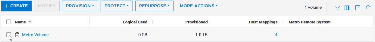
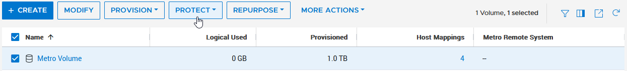
In this short blog, I’ll walk you through the configuration of a metro volume and prove that it’s possible to enable a metro session in just six clicks, when the remote system and a standard volume are already setup.
A metro volume is a volume that runs a bi-directional synchronous replication between two different sites. Hosts using either side of a metro volume get active-active simultaneous access on both sides of the metro volume. The use case for a PowerStore metro volume is a vSphere Metro Storage Cluster (also known as a stretched cluster configuration) with VMware vSphere.
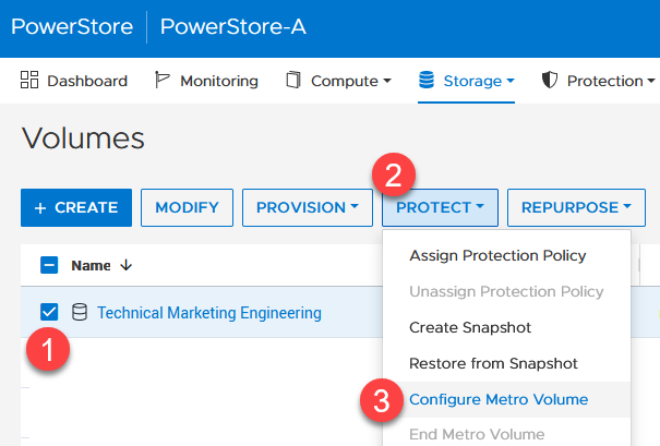
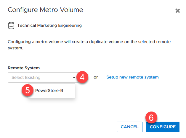
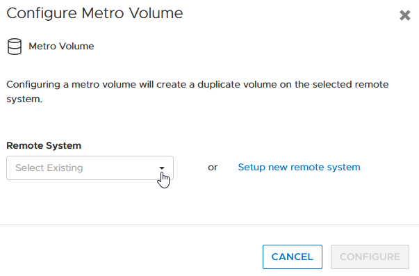
PowerStore metro volumes support a latency maximum of 5ms and a maximum distance of 80miles/100km. After the operator sets up a metro volume, PowerStore internally creates a metro session to control the replication between the two sites. When the remote system relationship is set up on PowerStore, and the volume is mapped to one or more hosts, it requires just six additional clicks to set up a metro session for a standard volume, as shown here:
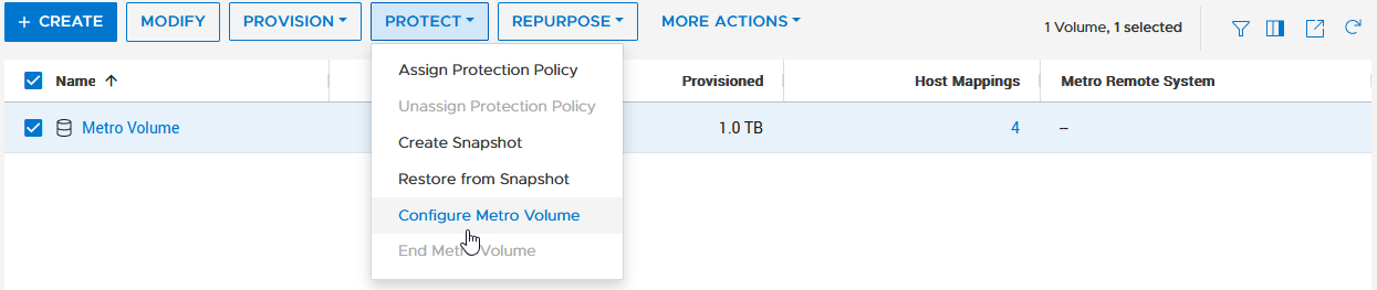
1. Select the volume. 2. Navigate to PROTECT. 3. Select Configure Metro Volume.
|
|
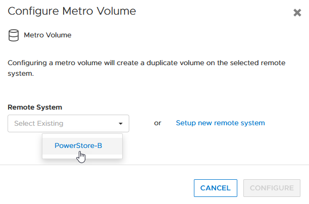
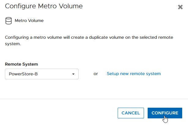
4. Click the pull down to select the remote system. 5. Select the remote system. 6. Click CONFIGURE |
|
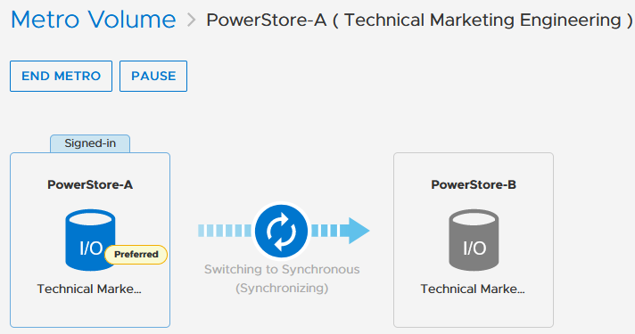
To mitigate any performance impact on the source system for the new, unsynchronized metro volume, PowerStore immediately starts with asynchronous replication and switches into synchronous replication once the data is in sync. |
|
Because a metro session replicates all IO synchronously, active-active host access is possible on both ends of the metro volume. Even during the initial synchronization, hosts can map the new volume on the replication destination but only get active paths when the metro session is in an active-active state.
|
|

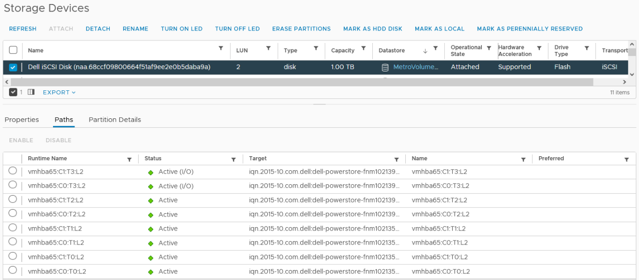
When hosts are in a uniform configuration, active paths are provided by both participating PowerStore clusters. The following example shows a uniformly connected host that can access the metro volume in two storage networks (fabrics).
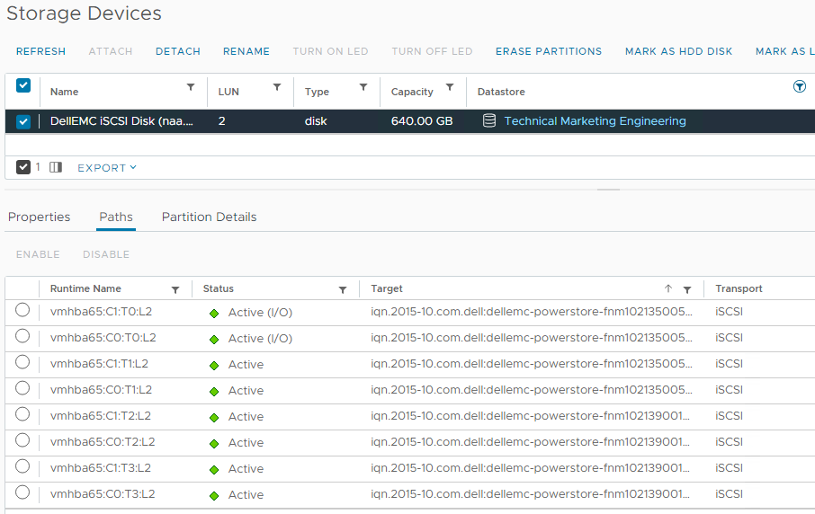
Here is the mapping of individual NICs in this example:
ESXi Host | NIC 1 | PowerStore-A | Node A Node B | C0:T0:L2 (Active I/O) C0:T1:L2 |
|
| PowerStore B | Node A Node B | C0:T2:L2 C0:T3:L2 |
| NIC2 | PowerStore-A | Node A Node B | C1:T0:L2 (Active I/O) C1:T1:L2 |
|
| PowerStore B | Node A Node B | C1:T2:L2 C1:T3:L2 |
Resources
Author: Robert Weilhammer, Principal Engineering Technologist
https://www.xing.com/profile/Robert_Weilhammer

PowerStore REST API: Using Filtering to Fine Tune Your Queries
Thu, 26 Jan 2023 17:40:56 -0000
|Read Time: 0 minutes
The PowerStore REST API provides a powerful way to manage a PowerStore cluster, mainly when using one’s own scripts [3] or automation tools.
In some areas of PowerStore, almost all of its functionality is available when using the REST API – and sometimes even more when the required attributes are unavailable in the PowerStore Manager GUI.
A great place to start learning more about the REST API is the integrated SwaggerUI [2] which provides online documentation with test functionality on your system. SwaggerUI uses an OpenAPI definition. Some 3rd party tools can leverage the same OpenAPI definition, and can be downloaded from SwaggerUI. SwaggerUI is available on all PowerStore models and types by using https://<PowerStore>/swaggerui in your preferred browser.
When working with the PowerStore REST API it’s not always obvious how to query some attributes. For example, it’s easy to filter for a specific volume name to get id, size, and type of a volume or volumes when using “*” as wildcard:
To query for all volumes with “Test” somewhere in its name, we could use
name=like.*Test*
as the query string:
% curl -k -s -u user:pass -X GET "https://powerstore.lab/api/rest/volume?select=id,name,size,type&name=like.*Test*" | jq .
[
  {
    "id": "a6fa6b1c-2cf6-4959-a632-f8405abc10ed",
    "name": "TestVolume",
    "size": 107374182400,
    "type": "Primary"
  }
]
In that example, although we know that there are multiple snapshots for a particular volume, the REST API query that uses the parent volume name does not show the related snapshots. It’s because snapshots must not have the name of the parent volume in their name. From PowerStore Manager we know that this volume has three snapshots, but their names do not relate to the volume name: 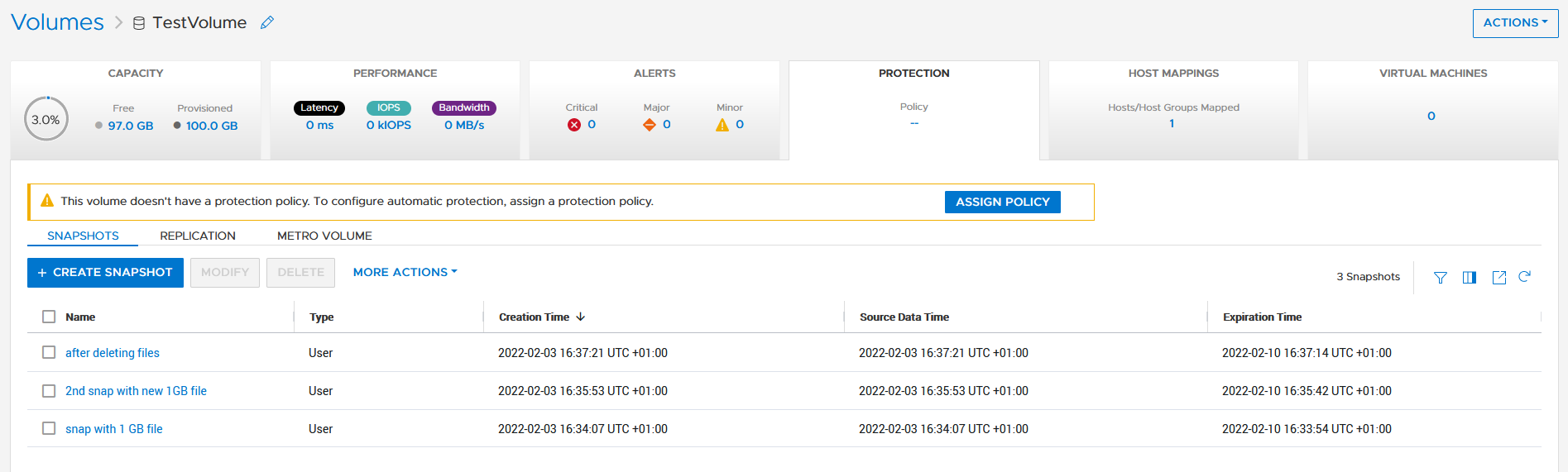
How is it possible to get the same output with a REST API query? We know that everything in PowerStore is managed with IDs, and the API description in SwaggerUI shows that a volume could have an attribute parent_id underneath the protection_data section.
All volumes with a protection_data->>parent_id that is equal to the ID of our “TestVolume” show the related snapshots for the TestVolume. The key for the query is the following syntax for the underlying attributes:
protection_data->>parent_id=eq.a6fa6b1c-2cf6-4959-a632-f8405abc10ed
The resulting curl command to query for the snapshot volumes shows the same syntax to select “creator_type” from a nested resource:
% curl -k -s -u user:pass -X GET 'https://powerstore/api/rest/volume?select=id,name,protection_data->>creator_type,creation_timestamp&protection_data->>parent_id=eq.a6fa6b1c-2cf6-4959-a632-f8405abc10ed' | jq .
[
  {
    "id": "051ef888-a815-4be7-a2fb-a39c20ee5e43",
    "name": "2nd snap with new 1GB file",
     "creator_type": "User",
"creation_timestamp": "2022-02-03T15:35:53.920133+00:00"
},
{
"id": "23a26cb6-a806-48e9-9525-a2fb8acf2fcf",
"name": "snap with 1 GB file",
"creator_type": "User",
"creation_timestamp": "2022-02-03T15:34:07.891755+00:00"
},
{
"id": "ef30b14e-daf8-4ef8-8079-70de6ebdb628",
"name": "after deleting files",
"creator_type": "User",
"creation_timestamp": "2022-02-03T15:37:21.189443+00:00"
}
]Resources
For more white papers, blogs, and other resources about PowerStore, please visit our PowerStore Info Hub.
Related resources to this blog on the Info Hub:
- For a general PowerStore Manager overview, see Dell PowerStore Manager Overview
- To learn more about volumes and volume families: PowerStore: Snapshots and Thin Clones
- An alternative to REST API: What is PowerStoreCLI Filtering?
For some great video resources referenced in this blog, see:
- [1] Dell PowerStore REST API Part 1 - Introduction
- [2] Dell PowerStore REST API Part 2 - PowerStore SwaggerUI
- [3] Dell PowerStore REST API Part 3 - Python script example
See also this PowerStore product documentation:
Author: Robert Weilhammer, Principal Engineering Technologist

Provision PowerStore Metro Volumes with Dell Virtual Storage Integrator (VSI)
Tue, 30 Aug 2022 19:55:24 -0000
|Read Time: 0 minutes
Since PowerStoreOS 3.0, native metro volumes have been supported for PowerStore in vSphere Metro Storage Cluster configurations. With the new Virtual Storage Integrator (VSI) 10.0 plug-in for vSphere, you can configure PowerStore metro volumes from vCenter without a single click in PowerStore Manager.
This blog provides a quick overview of how to deploy Dell VSI and how to configure a metro volume with the VSI plug-in in vCenter.
Components of VSI
VSI consists of two components—a VM and a plug-in for vCenter that is deployed when VSI is registered for the vCenter. The VSI 10.0 OVA template is available on Dell Support and is supported with vSphere 6.7 U2 (and later) through 7.0.x for deployments with an embedded PSC.
Deployment
A deployed VSI VM requires 3.7 GB (thin) or 16 GB (thick) space on a datastore and is deployed with 4 vCPUs and 16 GB RAM. The VSI VM must be deployed on a network with access to the vCenter server and PowerStore clusters. During OVA deployment, the import wizard requests information about the network and an IP address for the VM.
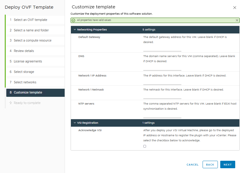
When the VM is deployed and started, you can access the plug-in management with https://<VSI-IP>.
Register VSI plug-in in vCenter
A wizard helps you register the plug-in in a vCenter. Registration only requires that you set the VSI Redis Password for the internal database and username/password.
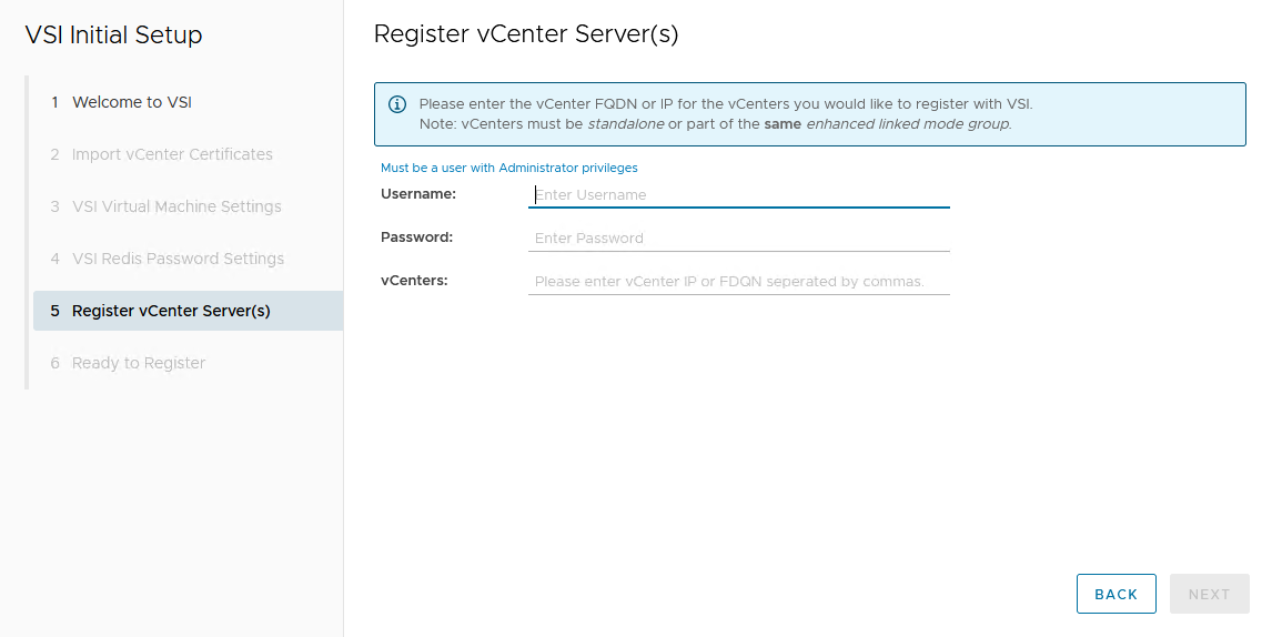
After the VSI VM is configured, it takes some time for the plug-in to appear in vCenter. You might be required to perform a fresh login to the vSphere Client before the Dell VSI entry appears in the navigation pane.
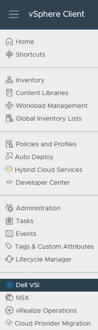
From the Dell VSI dashboard, use the + sign to add both PowerStore clusters used for metro volumes.
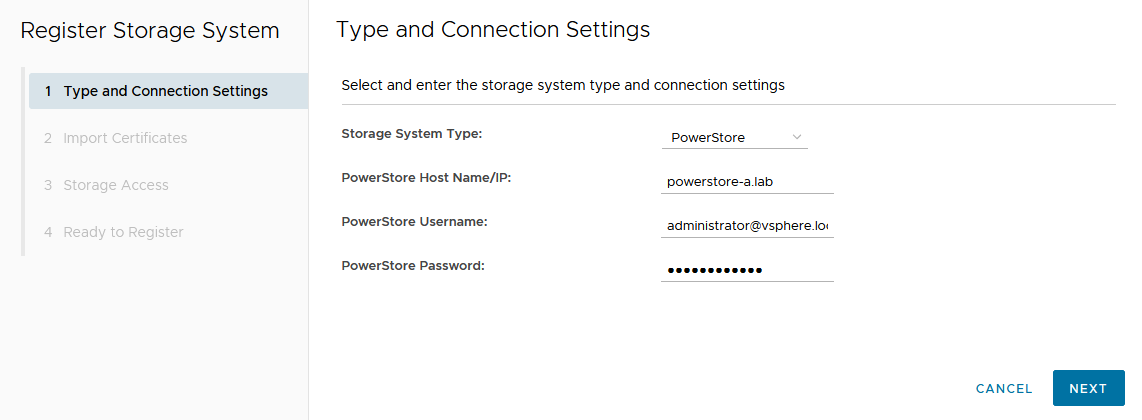
Configure a metro volume with the VSI plug-in
As with PowerStore Manager, creating a metro volume with the VSI plug-in requires three steps:
- Create and map a standard volume.
- Configure metro for the newly created volume.
- Map the second metro volume to the hosts.
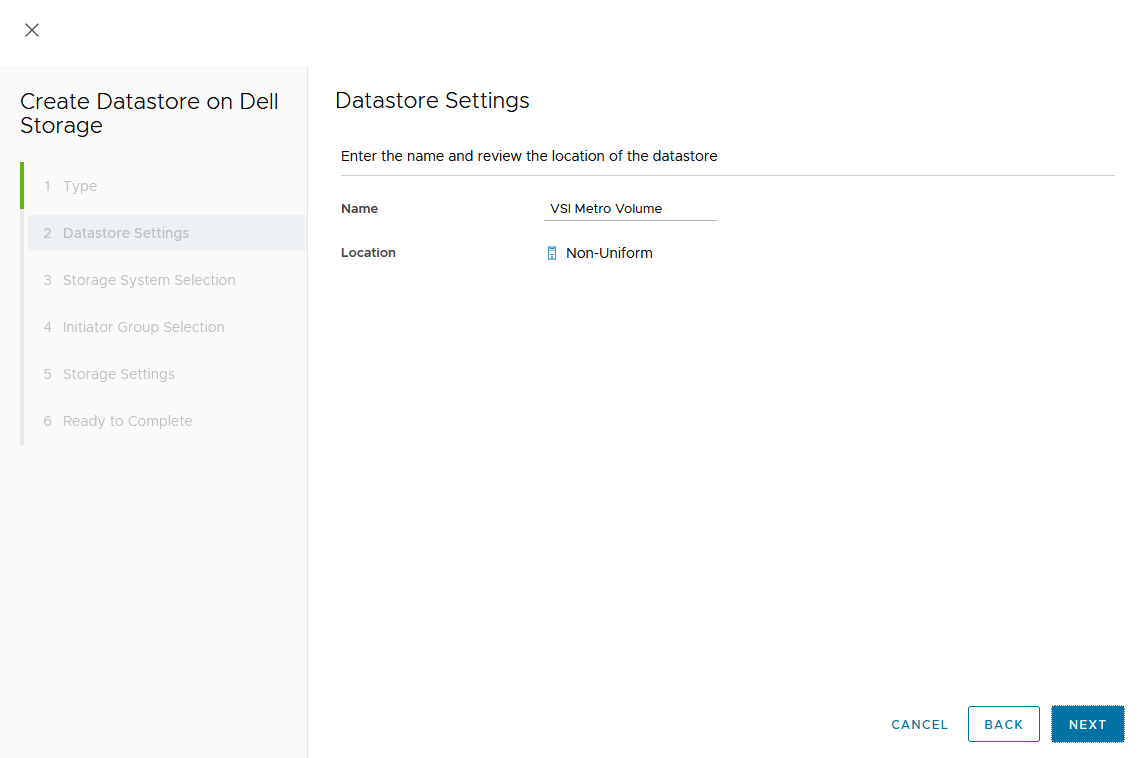
The following example adds a new metro volume to cluster Non-Uniform, which already has existing metro volumes provisioned in a Non-Uniform host configuration. Esx-a.lab is local to PowerStore-A, and esx-b.lab is local to PowerStore-B.
- Create and map a standard volume in vSphere.
Use the Actions menu either for a single host, a cluster, or even the whole data center in vSphere. In this example, we chose Dell VSI > Create Datastore for the existing cluster Non-Uniform. - Configure metro for the newly created volume.
The VSI Create Datastore wizard leads us through the configuration.- For a metro volume, select the volume type VMFS.
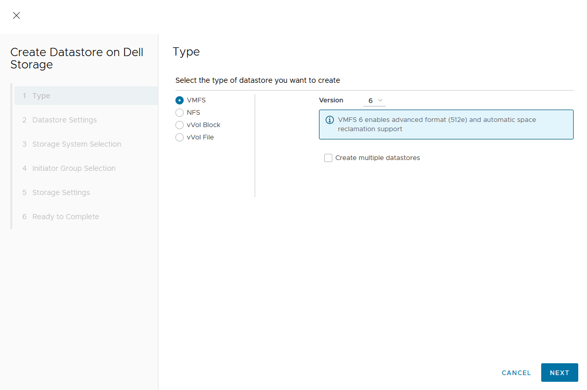
- Provide a name for the new volume.
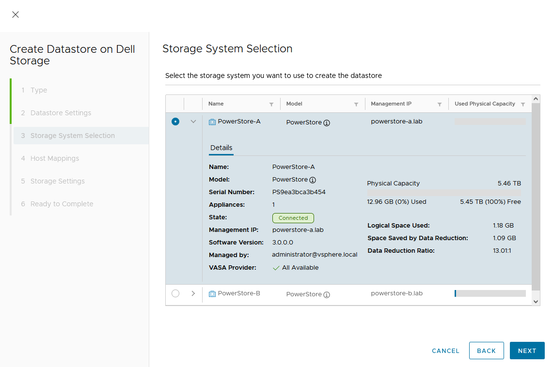
- Select the storage system.
- For a metro volume, select the volume type VMFS.
In the dialog box, you can expand the individual storage system for more information. We start with PowerStore-A for esx-a.lab.
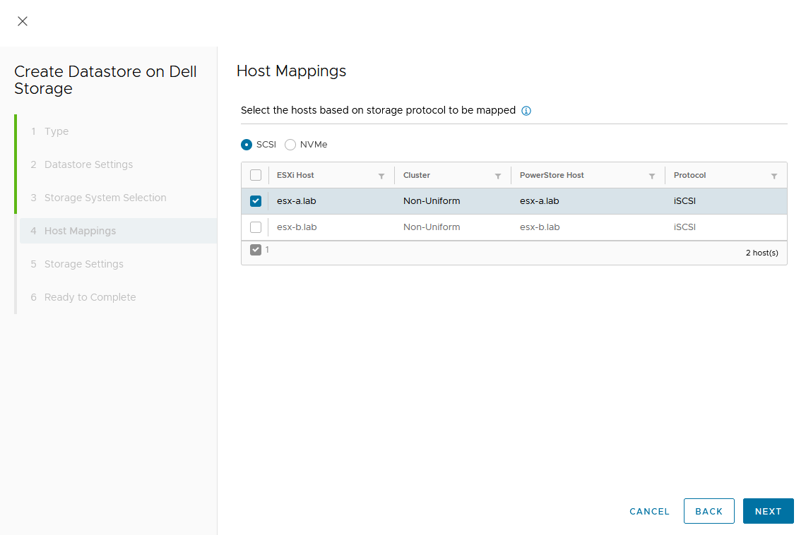
d. Map the host.
As this is a Non-Uniform cluster configuration, only esx-a.lab is local to PowerStore-A and should be mapped to the new volume on PowerStore-A.
e. Set a Capacity and select other volume settings such as Performance Policy or Protection Policy.
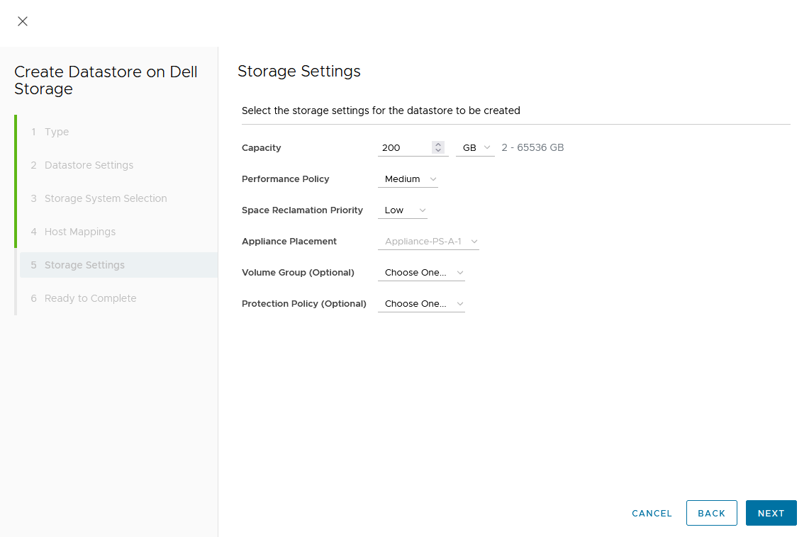
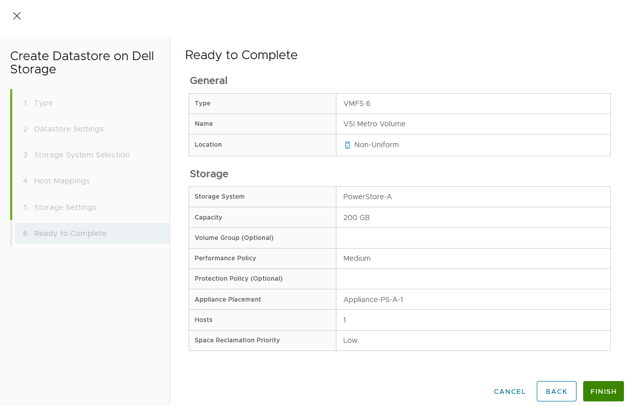
Wizard summary page:
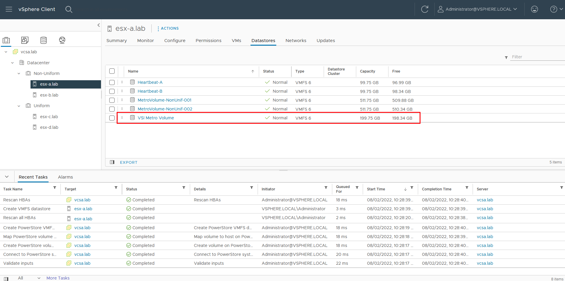
Upon completion, the volume is configured and mapped to the host. The following screenshot shows the new volume, VSI Metro Volume, and the tasks that ran to create and map the volume in vSphere.
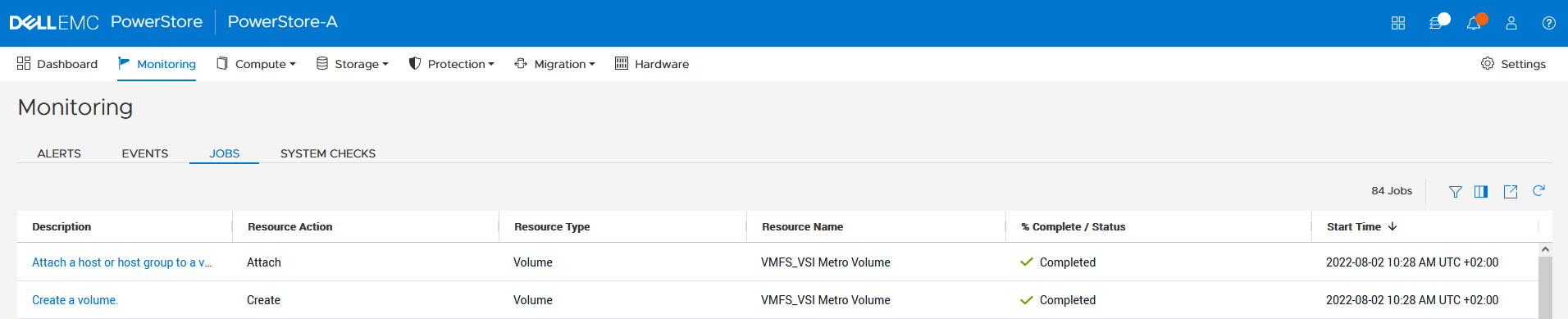
For reference, the related jobs in PowerStore Manager for PowerStore-A are also available at Monitoring > Jobs:
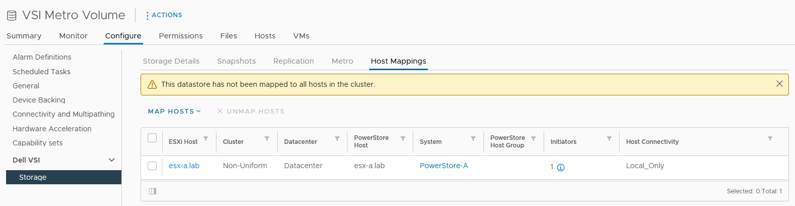
f. Select the VSI Metro Volume datastore, and then select Configure > Dell VSI > Storage to see the details for the backing device.
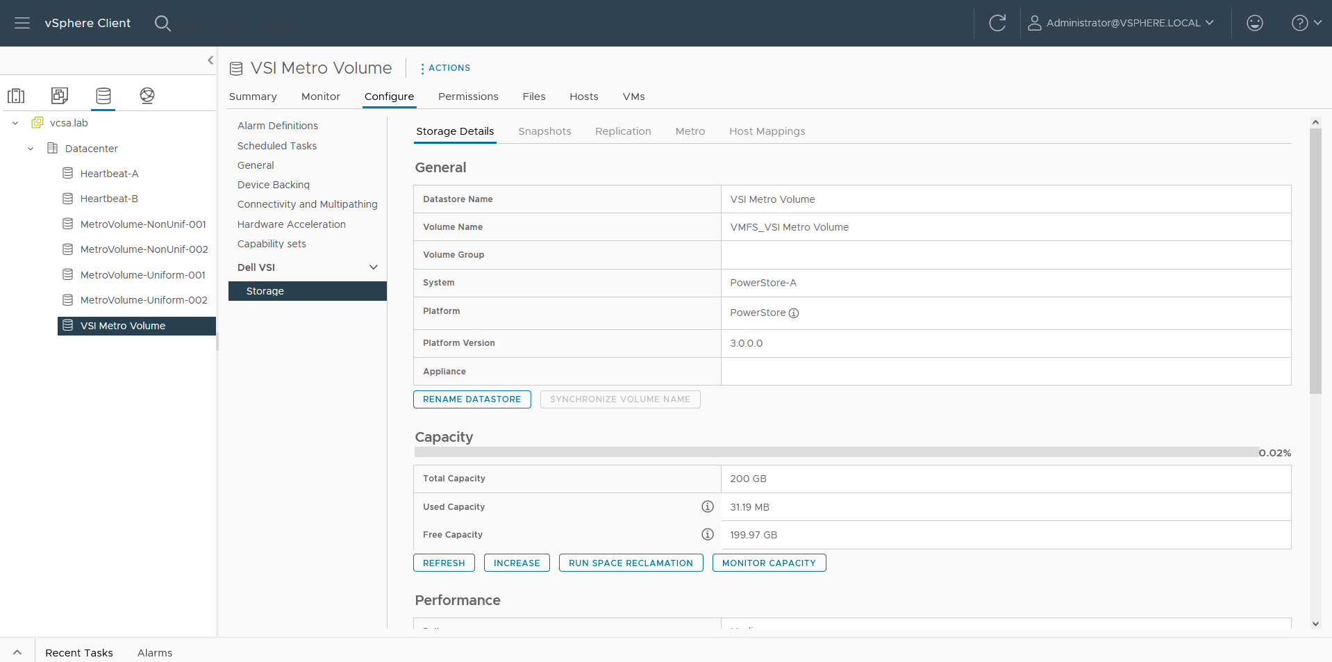
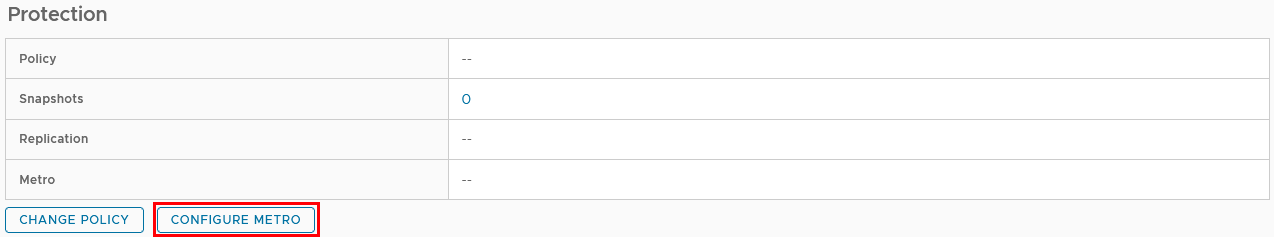
g. On the Storage Details tab under Protection, click Configure Metro.
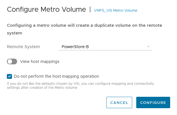
h. In the Configure Metro Volume dialog box, specify the Remote System and whether host mapping should be performed.
Depending on host registrations on PowerStore, automatic mapping may be unwanted and can be skipped. In this example, PowerStore-B has also the esx-a.lab host registered to provide access to one of the heartbeat volumes required for vSphere HA. The host mapping operation in the Create Datastore wizard creates an unwanted mapping of the volume from PowerStore-B to esx-a.lab. To configure manual mapping after the metro volume is created, select Do not perform the host mapping operation.
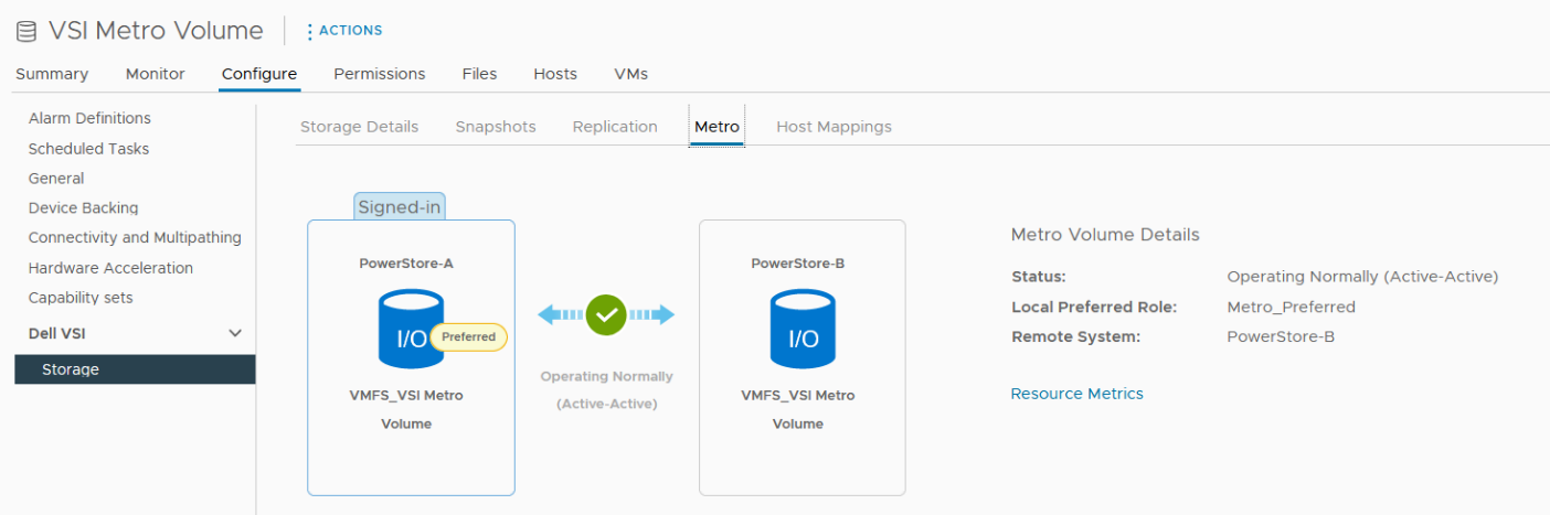
The metro volume is immediately configured on PowerStore and the Metro tab in Dell VSI > Storage view shows the status for the metro configuration.
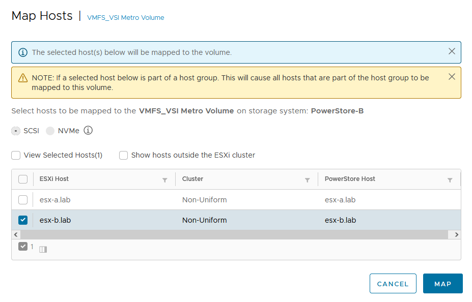
3. Map the second metro volume to the host.
Because we skipped host mapping when we created the metro volume, we must map the esx-b.lab host to the metro volume on PowerStore-B on the Host Mappings tab. Currently, the volume is only mapped from PowerStore-A to esx-a.lab.
a. Select Map Hosts > PowerStore-B to open the Map Hosts dialog box.
b. Map the volume on PowerStore-B for esx-b.lab.
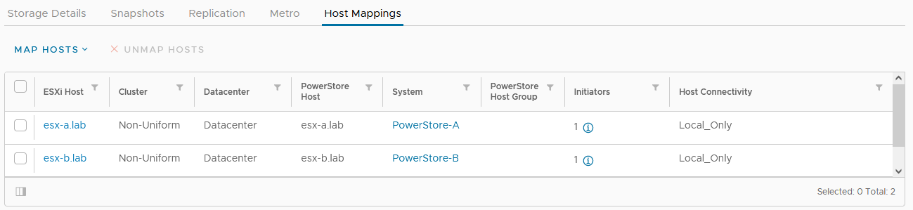
The host mapping overview shows the result and concludes the metro volume configuration with Virtual Storage Integrator (VSI) plugin.
Resources
- Dell Virtual Storage Integrator (VSI) for VMware vSphere Client Version 10.0 Product Guide
- Dell PowerStore Protecting Your Data—Metro Protection
- Dell PowerStore: Metro Volume
Author: Robert Weilhammer, Principal Engineering Technologist
https://www.xing.com/profile/Robert_Weilhammer

Guide for Configuring PowerStore with an SSL Certificate
Tue, 30 Aug 2022 14:11:47 -0000
|Read Time: 0 minutes
SSL certificates are commonly used when browsing the internet. Even corporate intranet pages are usually protected with an encrypted SSL connection. The two major security improvements when using SSL certificates are:
- Authenticity to prove a trusted server
- Encryption to protect (sensitive) data
Let’s start with some quick basics. I guess everyone has seen the nice error message about expired or invalid certificates in a browser. Some browsers even don’t allow you to continue when hitting a page with an expired certificate.
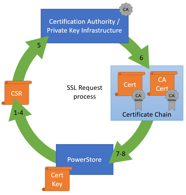
When Dell PowerStore is installed, it internally generates a self-signed certificate to allow data encryption between browser and PowerStore. Because the signed certificate is not trusted by the browser, a warning indicates that the page is not trusted. To mitigate the warning, PowerStoreOS allows the administrator to change the out-of-the box self-signed certificate with a trusted SSL certificate, ideally signed by a trusted certification authority (CA).
Besides the major commercial and public CAs, some companies run their own company-wide certificate authority. A private CA is usually part of a Private Key Infrastructure (PKI) and can provide certificates for different purposes. To allow the browser to validate certificates, the certificate of the private CA needs to be installed as a trusted Certificate Authority in the browser.
A certificate always consists of at least two parts:
- A secret key which is used to sign other certificates or to encrypt data
- A public key which is included in a certificate
When a certificate or data is signed or encrypted with a private key, the public shared key can be used to decrypt the information. Fingerprints within the certificate file help verify whether the shared key and decrypted information can be trusted.
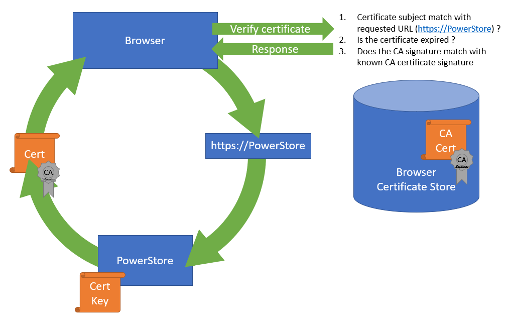
The structure of trusted certificates is always hierarchical and based on a Root CA certificate, which is at the top of the trust chain. A Root CA can have one or more Intermediate CAs, which are usually used to sign a server certificate by a certificate authority. In the same way when a client requests data from an SSL protected site, the server uses the certificate key to sign and encrypt the data and sends the response with the public certificate to the client. The client uses the response to check and validate the certificate attributes. These important attributes are the “valid from” and “valid to” timestamps, whether the URL matches the subject of the certificate, and whether the certificate is signed by a trusted CA certificate in the client certificate store. The check against a trusted CA certificate proves the authenticity. When all checks are passed, the browser indicates that the page can be trusted.
SSL certificates involve some different files:
Certificate | Description |
Certificate “key” file | Contains the key to encrypt and sign data. The key file should be kept safe. |
Certificate Sign Request (CSR) | The certificate sign request is generated with information from the key file and contains the information for a CA to issue a certificate file. Included information for a CSR generated with PowerStore: Subject: Concatenated string containing Organization, Organizational Unit, Location, State, and Common Name as given in PowerStore Manager when creating the CSR. SAN: A X509v2 extension called “Subject Alternate Names” which is the DNS and IP information as entered Public-Key: The public part of the private key file |
Certificate file | This could be either a single certificate or a certificate chain. A certificate chain is a set of concatenated certificates that allows clients to validate a certificate down to a trusted (CA) certificate. There are different file formats possible: PEM: “Privacy-Enhanced Mail” is commonly used to exchange certificates DER: “Distinguished Encoding Rules” is a binary encoding for PEM files PFX/PKCS: Another type called personal information exchange format When dealing with SSL certificates for Dell PowerStore, the PEM format is used. |
CA Certificate / | This is the public certificate of the issuer CA of a certificate. A PowerStore does not know anything of the issuer and needs the CA certificate to build the whole chain of trust for the certificate. Sometimes the file includes the whole certificate chain that consists of concatenated PEM certificates CA -> [Intermediate CA] -> PowerStore The included certificates in a chain depend on the issuer of a certificate. For PowerStore, we require the chain of certificates in following order:
|
Since PowerStoreOS 2.0, it’s possible to install 3rd party / signed server certificates for PowerStore T models in a block only deployment using PowerStore REST API or PowerStore CLI. PowerStoreOS 3.0 adds support for PowerStore T unified deployments and a GUI in PowerStore Manager for SSL import. This provides a comfortable way to generate a certificate sign request (CSR) and install the certificate. The certificate key file is stored in PowerStore and cannot be exported.
The next sections describe how to use PowerStore Manager and the PowerStore CLI to install a third party SSL certificate.
Installing a third party SSL certificate (PowerStore Manager)
The following figure illustrates the steps required to deploy the certificate in PowerStore Manager:
- Log into PowerStore Manager.
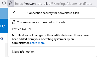
Note that your browser shows that the connection is not secure: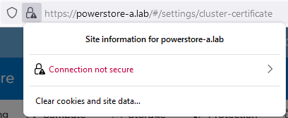
- Go to PowerStore Settings > Security > Signed Cluster Certificate.
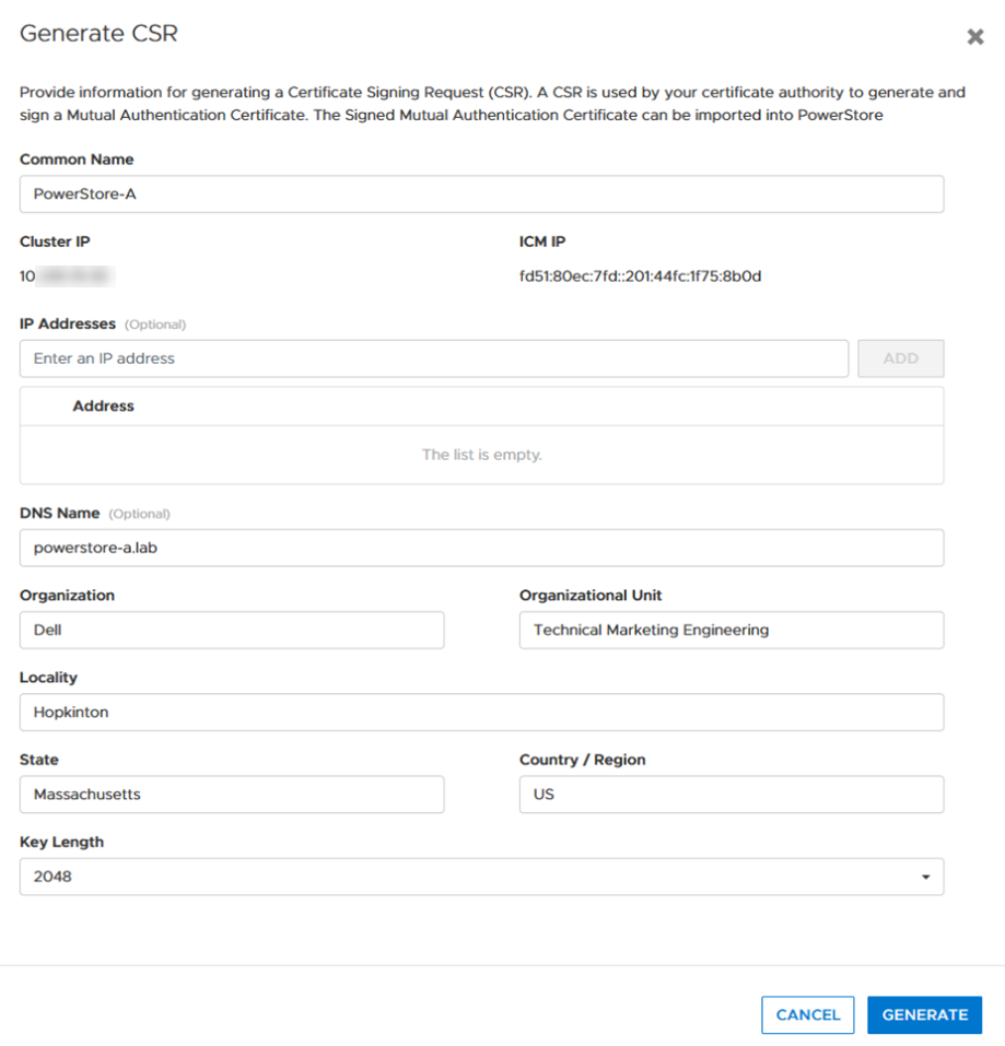
- Click the Generate CSR button and enter the required information to request a certificate.
a. Common Name Name of the certificate – usually the PowerStore cluster name
b. Cluster and ICM IP Mandatory for the Certificate and can’t be changed
c. IP Addresses Alternate IP Addresses which should appear in the certificate.
d. DNS name PowerStore FQDN
e. Organization Company Name
f. Organizational Unit Team / Organization
g. Locality Town
h. State State
i. Country/Region Two-letter country code
j. Key Length 2048 or 4096
4. When the CSR is created, click copy to clipboard and export the CSR content to a file -> for example, PowerStore.CSR
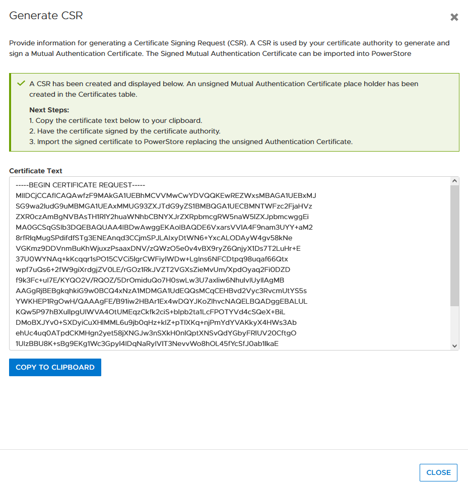
Optional: you can use the openssl tool to extract the contents of the CSR in a human readable format:
# openssl req -noout -text -in PowerStore.CSR
5. Send the CSR to your Certification Authority / PKI.
When there is an option to specify the format of the response, choose “PEM” format for the PowerStore and CA certificate. These files can be easily concatenated to a single certificate chain file (using the Linux CLI or a text editor) for import:
# cat powerstore.crt CA.crt > chain.crt
6. If not completed already, import the CA Certificate into your browser.
7. In PowerStore Manager, import the certificate chain in same screen where the CSR was generated.
Important: Sometimes the certificate file is in blocks. PowerStore expects the certificate in single lines, as in the following example with a PowerStore- and CA certificate:
-----BEGIN CERTIFICATE-----
[...Single line PowerStore certificate content...]
-----END CERTIFICATE-----
-----BEGIN CERTIFICATE-----
[...Single line CA Certificate certificate content...]
 -----END CERTIFICATE-----
If the individual certificates are not on a single line, the import will fail with the error “Failed to update certificate in credential store. Please verify your certificate chain. (0xE09010010013)”. You can use the openssl tool to verify that the file is ok:
# openssl x509 -in powerstore-chain.crt -noout -text
8. Start using PowerStore with a trusted HTTPS connection.
Installing a third party SSL certificate (PowerStore CLI)
Follow these steps to generate a certificate with PowerStore CLI for PowerStore-A. Be sure to format the CSR and certificate file correctly.
1. Generate CSR:
cli> x509_certificate csr -type Server -service Management_HTTP -scope External -key_length 2048 -common_name PowerStore-A -dns_name powerstore-a.lab -organizational_unit "Technical Marketing Engineering" -organization Dell -locality Hopkinton -state Massachusetts -country US
The response shows an ID and the CSR in a block. Keep the ID noted somewhere as it will be required for import. Also, use a text editor to make sure BEGIN- and END CERTIFICATE REQUEST are each on their own line when requesting the certificate:
-----BEGIN CERTIFICATE REQUEST-----
[... a nice formatted block or single line ...]
 -----END CERTIFICATE REQUEST-----
2. Use CSR content to request the certificate.
3. Ensure that the issued certificate file is a single line string as required for import in PowerStore Manager. Note that the required line breaks need to be “\n”.
4. Import the certificate by using the ID and the certificate string:
cli> x509_certificate -id f842d778-0b28-4012-b8d5-66ead64d38e4 set -is_current yes -certificate “-----BEGIN CERTIFICATE-----\n[...Single line PowerStore certificate content...]\n-----END CERTIFICATE-----\n-----BEGIN CERTIFICATE-----\n[...Single line CA Certificate certificate content...] \n-----END CERTIFICATE-----"
Terms used:
CA Certification Authority
CN Common Name
CSR Certificate Sign Request
chain Single “chain” file with concatenated certificates
key Private certificate key
PEM Privacy-Enhanced Mail and commonly used to exchange certificates
SAN Subject Alternate Name
Resources
Author: Robert Weilhammer, Principal Engineering Technologist

Intro to Native Metro Volume Support with a PowerStore CLI Example
Wed, 27 Jul 2022 13:50:50 -0000
|Read Time: 0 minutes
Introduction
With native metro volume support, PowerStoreOS 3.0 introduces an additional feature that helps prevent your production from outages caused by a failure in your VMware vSphere Metro Storage Cluster (vMSC) environment. The Metro Volume feature is available at no additional cost on PowerStore and can be used to protect VMFS datastores.
A vMSC configuration is a stretched cluster architecture where ESXi hosts can be in two different sites in metro distance (100 km / 60 miles) while accessing a synchronously replicated storage resource. The PowerStore Metro Volume feature provides concurrent and full active/active host IO on both participating PowerStore cluster configurations.
Although this adds additional latency, a PowerStore Metro Volume ensures that all host I/O is committed on both mirror volumes of a Metro Volume before the host receives an acknowledgement for the write I/O. To survive a disaster with minimal, or even better, no interruption to your production, PowerStore has built in a mechanism to protect your data from a split-brain situation in case of a failure or disaster. PowerStore is designed to allow only active-active workloads on both sides of a Metro Volume when data can be replicated between the Metro Volume mirrors on both PowerStore clusters.
From a topology point of view, PowerStore supports two different configuration scenarios. There is a Non-Uniform configuration where hosts only have access to the local PowerStore system: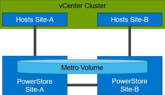
There is also a Uniform configuration where hosts can access both the local and remote PowerStore.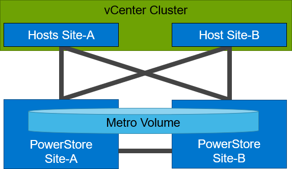
Even though they look similar, the benefits of the different topologies are in the details.
A Non-Uniform host configuration reduces complexity because it requires less configuration and only provides local access to the volume that has the least utilization on the link between the two sites. However, in a failure situation with the local PowerStore array, or during a link failure, local hosts can lose access to the Metro Volume. In this situation, VMware HA needs to restart any VMs on the affected datastore using the surviving hosts on the opposite site. There should be sufficient host resources available on each site to allow running the most critical VMs while the peer site is not available.
In a Uniform host configuration, the hosts have additional links to the remote PowerStore cluster that can be used during a failure situation. If the Metro Volume is not accessible on the local PowerStore cluster due a failure or link outage, the hosts can utilize the cross links to access the volume on the remote site. In this scenario, a VM could survive the failure because hosts can switch the working path to the remote system. Under normal operations, the host I/O should be kept within the local site to avoid unnecessary bandwidth utilization on the link between the sites for the workload and to minimize latency.
Let me show you a quick example where we assume a theoretical local latency of 0.5ms and 2ms between the sites.
1. The host is using a link to the local array as primary path to write to a Metro Volume. The theoretical latency for the I/O would be as follows:
- 0.5ms workload from the host to the local storage
- 2.0ms to replicate the workload to the remote storage. Workload uses a link between the sites.
- 2.0ms to receive the commit from the remote storage on the local storage
- 0.5ms for the commit to the host
In total, we would see a 5.0ms latency for the I/O and the workload is sent only once across the link between the sites for replication (A-B).
2. When the host is using the links to the remote array as primary path, we would see following situation:
- 2.0ms to send the workload to the remote storage. The workload uses a link between the sites.
- 2.0ms to replicate the workload to a peer. The workload uses a link between the sites.
- 2.0ms for the commit from the peer array to the remote storage
- 2.0ms for the commit to the host
In total, we would see a theoretical latency of 8.0ms for the same I/O because the workload and commits are always utilizing the link between the sites: once, when host writes data to the remote array (A to B), and again when the write is replicated to peer storage (B-A) plus the required commits.
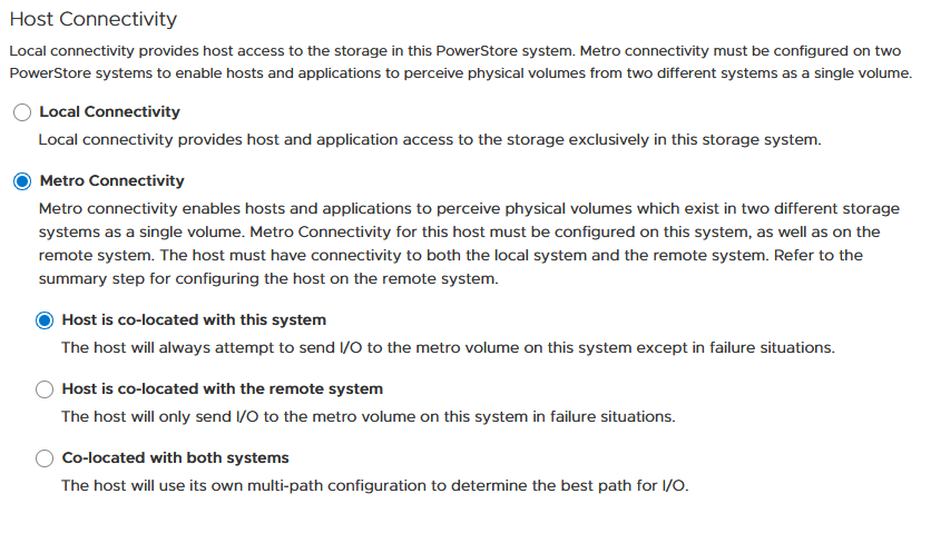
To ensure the selection of optimal paths, PowerStore provides information for optimal path selection using the Asynchronous Logical Unit Access (ALUA) protocol. For the correct ALUA state, uniform hosts must be registered with their local or remote relation to each PowerStore cluster. There are four options when registering a host in PowerStore Manager:
- Local only – Used for Non-Uniform Metro Volumes and hosts serving only standard volumes.
- Host Co-Located with this PowerStore system – Indicates that the host is local (low latency) to the PowerStore, and should get the ALUA active/optimized paths.
- Host Co-Located with remote PowerStore system – Indicates that the host is a remote host (high latency), and host should get ALUA active/non-optimized paths.
- Host is Co-Located with both – Indicates that all hosts and PowerStore clusters are located in the same location with the same latency.
When a host is configured with a metro connectivity option for Uniform Metro Volume, PowerStore provides default ALUA path information for non-metro volumes standard volumes.
With Native Multipathing’s (NMP) default path selection policy (PSP) of “round robin” (RR), the connected ESXi hosts use the provided ALUA path information to determine the optimal working path down to the volume. When more than one active/optimized path is available, ESXi PSP round robin measures the latency to the volume to select the most optimal working path. The current working path is indicated with the status “Active (I/O)” in vCenter, while other paths only show the status “Active”. The following figure shows the path states for an ESXi host in a Uniform host configuration after a Metro Volume configuration is finished.
After hosts are set up in PowerStore manager, we can start to configure a Metro Volume. This is possible in just a few steps on a single PowerStore cluster:
- To set up a Remote Systems relationship with the peer PowerStore, select Protection > Add Remote System.
- Use the Add Volume wizard to create and map a standard volume.
- In the Volumes page, configure a Metro Volume with six clicks.
a. Select the new volume.
b. Click Protect.
c. Configure Metro Volume
d. Click on the Remote System pull down.
e. Select an existing remote system (or set up a new remote system relationship with another PowerStore cluster).
f. Click configure to start the configuration.
4. On the peer PowerStore cluster, map the new Metro Volume to the hosts.
5. Use the new Metro Volume to create a VMFS datastore.
Aside from using PowerStore Manager, it’s also possible to use the PowerStore REST API or the PowerStore CLI to set up a Metro Volume in just a few steps. In this blog, I want to show you the required steps in a PowerStore CLI session (pstcli -d <PowerStore> -session) to set up Metro Volume on PowerStore on a configured pair of PowerStore systems (as shown in the previous figure) for uniform host connectivity:
1. On PowerStore Manager PowerStore-A
a. Create Remote Systems relationship:
x509_certificate exchange -service Replication_HTTP -address <IP-Address PowerStore-B> -port 443 -username admin -password <YourSecretPassword>
 remote_system create -management_address <IP-Address PowerStore-B> -management_port 443 -remote_username admin -remote_password <YourSecretPassword> -type PowerStore -data_network_latency Low
b. Register ESXi hosts for Uniform host connectivity:
host create -name esx-a.lab -os_type ESXi -initiators -port_name iqn.1998-01.com.vmware:esx-a:<…>:65 -port_type iSCSI -host_connectivity Metro_Optimize_Local
host create -name esx-b.lab -os_type ESXi -initiators -port_name iqn.1998-01.com.vmware:esx-b:<…>:65 -port_type iSCSI -host_connectivity Metro_Optimize_Remote
c. Prepare and map a standard volume:
volume create -name MetroVolume-Uniform -size 1T
volume -name MetroVolume-Uniform -attach esx-a.lab
volume -name MetroVolume-Uniform -attach esx-b.lab
d. Configure the volume as a Metro Volume:
volume -name MetroVolume-Uniform configure_metro -remote_system_name PowerStore-B
2. On PowerStore Manager PowerStore-B
a. Register ESXi hosts for Uniform host connectivity:
host create -name esx-a.lab -os_type ESXi -initiators -port_name iqn.1998-01.com.vmware:esx-a:<…>:65 -port_type iSCSI -host_connectivity Metro_Optimize_Remote
host create -name esx-b.lab -os_type ESXi -initiators -port_name iqn.1998-01.com.vmware:esx-b:<…>:65 -port_type iSCSI -host_connectivity Metro_Optimize_Local
b. Map Volume to ESXi hosts:
volume -name MetroVolume-Uniform -attach esx-a.lab
volume -name MetroVolume-Uniform -attach esx-b.lab
c. Monitor Metro Volume (optional):
replication_session show -query type=Metro_Active_Active -select state,progress_percentage,data_transfer_state
3. In vCenter
a. Rescan the SCSI bus.
b. Configure the VMFS datastore with the new Metro Volume.
For more information, see the following resources.
Resources
- vSphere Metro Storage Cluster (vMSC)
- White paper: Dell PowerStore: Metro Volume
- White paper: Dell PowerStore: Replication Technologies
Author: Robert Weilhammer, Principal Engineering Technologist

PowerStore REST API: Using Filtering to Fine Tune Your Queries
Fri, 11 Mar 2022 16:03:19 -0000
|Read Time: 0 minutes
The PowerStore REST API provides a powerful way to manage a PowerStore cluster, mainly when using one’s own scripts [3] or automation tools.
In some areas of PowerStore, almost all of its functionality is available when using the REST API – and sometimes even more when the required attributes are unavailable in the PowerStore Manager GUI.
A great place to start learning more about the REST API is the integrated SwaggerUI [2] which provides online documentation with test functionality on your system. SwaggerUI uses an OpenAPI definition. Some 3rd party tools can leverage the same OpenAPI definition, and can be downloaded from SwaggerUI. SwaggerUI is available on all PowerStore models and types by using https://<PowerStore>/swaggerui in your preferred browser.
When working with the PowerStore REST API it’s not always obvious how to query some attributes. For example, it’s easy to filter for a specific volume name to get id, size, and type of a volume or volumes when using “*” as wildcard:
To query for all volumes with “Test” somewhere in its name, we could use
name=like.*Test*
as the query string:
% curl -k -s -u user:pass -X GET "https://powerstore.lab/api/rest/volume?select=id,name,size,type&name=like.*Test*" | jq .
[
  {
    "id": "a6fa6b1c-2cf6-4959-a632-f8405abc10ed",
    "name": "TestVolume",
    "size": 107374182400,
    "type": "Primary"
  }
]
In that example, although we know that there are multiple snapshots for a particular volume, the REST API query that uses the parent volume name does not show the related snapshots. It’s because snapshots must not have the name of the parent volume in their name. From PowerStore Manager we know that this volume has three snapshots, but their names do not relate to the volume name:
How is it possible to get the same output with a REST API query? We know that everything in PowerStore is managed with IDs, and the API description in SwaggerUI shows that a volume could have an attribute parent_id underneath the protection_data section.
All volumes with a protection_data->>parent_id that is equal to the ID of our “TestVolume” show the related snapshots for the TestVolume. The key for the query is the following syntax for the underlying attributes:
protection_data->>parent_id=eq.a6fa6b1c-2cf6-4959-a632-f8405abc10ed
The resulting curl command to query for the snapshot volumes shows the same syntax to select “creator_type” from a nested resource:
% curl -k -s -u user:pass -X GET 'https://powerstore/api/rest/volume?select=id,name,protection_data->>creator_type,creation_timestamp&protection_data->>parent_id=eq.a6fa6b1c-2cf6-4959-a632-f8405abc10ed' | jq .
[
  {
    "id": "051ef888-a815-4be7-a2fb-a39c20ee5e43",
    "name": "2nd snap with new 1GB file",
     "creator_type": "User",
"creation_timestamp": "2022-02-03T15:35:53.920133+00:00"
},
{
"id": "23a26cb6-a806-48e9-9525-a2fb8acf2fcf",
"name": "snap with 1 GB file",
"creator_type": "User",
"creation_timestamp": "2022-02-03T15:34:07.891755+00:00"
},
{
"id": "ef30b14e-daf8-4ef8-8079-70de6ebdb628",
"name": "after deleting files",
"creator_type": "User",
"creation_timestamp": "2022-02-03T15:37:21.189443+00:00"
}
]Resources
For more white papers, blogs, and other resources about PowerStore, please visit our PowerStore Info Hub.
Related resources to this blog on the Info Hub:
- For a general PowerStore Manager overview, see Dell PowerStore Manager Overview
- To learn more about volumes and volume families: PowerStore: Snapshots and Thin Clones
- An alternative to REST API: What is PowerStoreCLI Filtering?
For some great video resources referenced in this blog, see:
- [1] Dell PowerStore REST API Part 1 - Introduction
- [2] Dell PowerStore REST API Part 2 - PowerStore SwaggerUI
- [3] Dell PowerStore REST API Part 3 - Python script example
See also this PowerStore product documentation:
Author: Robert Weilhammer, Principal Engineering Technologist