


Intro to Native Metro Volume Support with a PowerStore CLI Example

Introduction
With native metro volume support, PowerStoreOS 3.0 introduces an additional feature that helps prevent your production from outages caused by a failure in your VMware vSphere Metro Storage Cluster (vMSC) environment. The Metro Volume feature is available at no additional cost on PowerStore and can be used to protect VMFS datastores.
A vMSC configuration is a stretched cluster architecture where ESXi hosts can be in two different sites in metro distance (100 km / 60 miles) while accessing a synchronously replicated storage resource. The PowerStore Metro Volume feature provides concurrent and full active/active host IO on both participating PowerStore cluster configurations.
Although this adds additional latency, a PowerStore Metro Volume ensures that all host I/O is committed on both mirror volumes of a Metro Volume before the host receives an acknowledgement for the write I/O. To survive a disaster with minimal, or even better, no interruption to your production, PowerStore has built in a mechanism to protect your data from a split-brain situation in case of a failure or disaster. PowerStore is designed to allow only active-active workloads on both sides of a Metro Volume when data can be replicated between the Metro Volume mirrors on both PowerStore clusters.
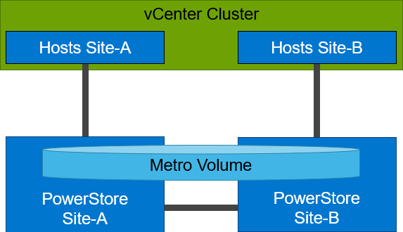
From a topology point of view, PowerStore supports two different configuration scenarios. There is a Non-Uniform configuration where hosts only have access to the local PowerStore system:
There is also a Uniform configuration where hosts can access both the local and remote PowerStore.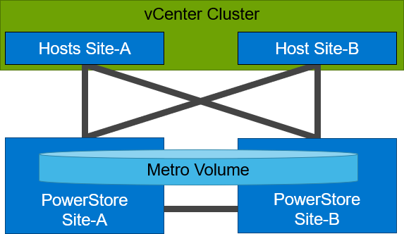
Even though they look similar, the benefits of the different topologies are in the details.
A Non-Uniform host configuration reduces complexity because it requires less configuration and only provides local access to the volume that has the least utilization on the link between the two sites. However, in a failure situation with the local PowerStore array, or during a link failure, local hosts can lose access to the Metro Volume. In this situation, VMware HA needs to restart any VMs on the affected datastore using the surviving hosts on the opposite site. There should be sufficient host resources available on each site to allow running the most critical VMs while the peer site is not available.
In a Uniform host configuration, the hosts have additional links to the remote PowerStore cluster that can be used during a failure situation. If the Metro Volume is not accessible on the local PowerStore cluster due a failure or link outage, the hosts can utilize the cross links to access the volume on the remote site. In this scenario, a VM could survive the failure because hosts can switch the working path to the remote system. Under normal operations, the host I/O should be kept within the local site to avoid unnecessary bandwidth utilization on the link between the sites for the workload and to minimize latency.
Let me show you a quick example where we assume a theoretical local latency of 0.5ms and 2ms between the sites.
1. The host is using a link to the local array as primary path to write to a Metro Volume. The theoretical latency for the I/O would be as follows:
- 0.5ms workload from the host to the local storage
- 2.0ms to replicate the workload to the remote storage. Workload uses a link between the sites.
- 2.0ms to receive the commit from the remote storage on the local storage
- 0.5ms for the commit to the host
In total, we would see a 5.0ms latency for the I/O and the workload is sent only once across the link between the sites for replication (A-B).
2. When the host is using the links to the remote array as primary path, we would see following situation:
- 2.0ms to send the workload to the remote storage. The workload uses a link between the sites.
- 2.0ms to replicate the workload to a peer. The workload uses a link between the sites.
- 2.0ms for the commit from the peer array to the remote storage
- 2.0ms for the commit to the host
In total, we would see a theoretical latency of 8.0ms for the same I/O because the workload and commits are always utilizing the link between the sites: once, when host writes data to the remote array (A to B), and again when the write is replicated to peer storage (B-A) plus the required commits.
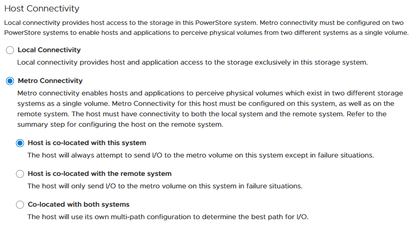
To ensure the selection of optimal paths, PowerStore provides information for optimal path selection using the Asynchronous Logical Unit Access (ALUA) protocol. For the correct ALUA state, uniform hosts must be registered with their local or remote relation to each PowerStore cluster. There are four options when registering a host in PowerStore Manager:
- Local only – Used for Non-Uniform Metro Volumes and hosts serving only standard volumes.
- Host Co-Located with this PowerStore system – Indicates that the host is local (low latency) to the PowerStore, and should get the ALUA active/optimized paths.
- Host Co-Located with remote PowerStore system – Indicates that the host is a remote host (high latency), and host should get ALUA active/non-optimized paths.
- Host is Co-Located with both – Indicates that all hosts and PowerStore clusters are located in the same location with the same latency.
When a host is configured with a metro connectivity option for Uniform Metro Volume, PowerStore provides default ALUA path information for non-metro volumes standard volumes.
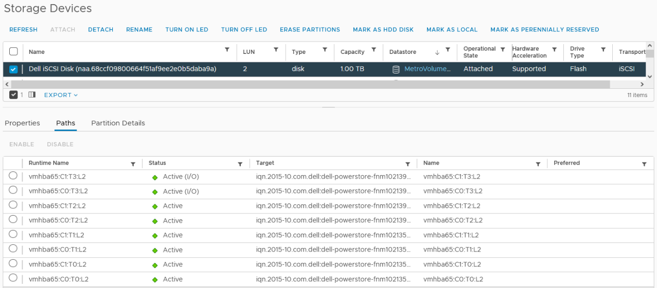
With Native Multipathing’s (NMP) default path selection policy (PSP) of “round robin” (RR), the connected ESXi hosts use the provided ALUA path information to determine the optimal working path down to the volume. When more than one active/optimized path is available, ESXi PSP round robin measures the latency to the volume to select the most optimal working path. The current working path is indicated with the status “Active (I/O)” in vCenter, while other paths only show the status “Active”. The following figure shows the path states for an ESXi host in a Uniform host configuration after a Metro Volume configuration is finished.
After hosts are set up in PowerStore manager, we can start to configure a Metro Volume. This is possible in just a few steps on a single PowerStore cluster:
- To set up a Remote Systems relationship with the peer PowerStore, select Protection > Add Remote System.
- Use the Add Volume wizard to create and map a standard volume.
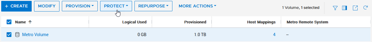
- In the Volumes page, configure a Metro Volume with six clicks.
a. Select the new volume.
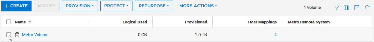
b. Click Protect.
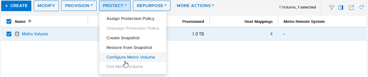
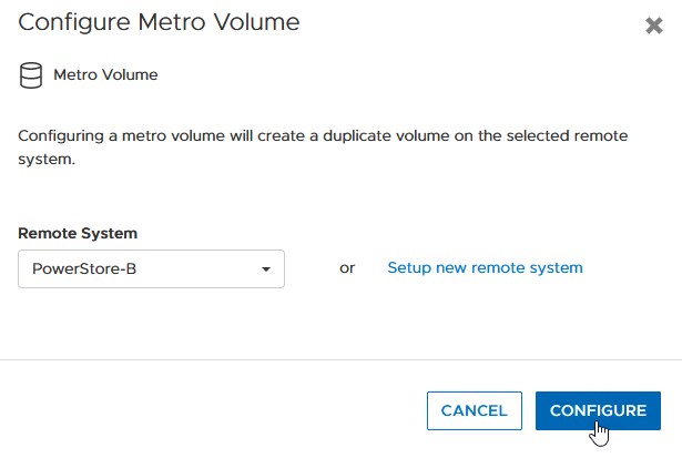
c. Configure Metro Volume
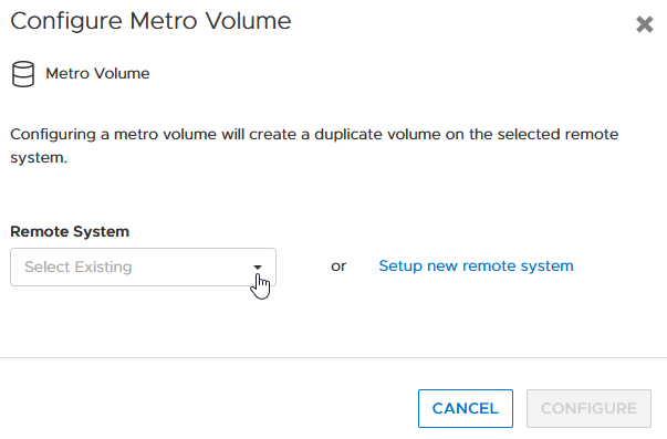
d. Click on the Remote System pull down.
e. Select an existing remote system (or set up a new remote system relationship with another PowerStore cluster).
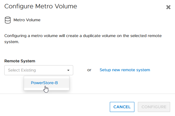
f. Click configure to start the configuration.
4. On the peer PowerStore cluster, map the new Metro Volume to the hosts.
5. Use the new Metro Volume to create a VMFS datastore.
Aside from using PowerStore Manager, it’s also possible to use the PowerStore REST API or the PowerStore CLI to set up a Metro Volume in just a few steps. In this blog, I want to show you the required steps in a PowerStore CLI session (pstcli -d <PowerStore> -session) to set up Metro Volume on PowerStore on a configured pair of PowerStore systems (as shown in the previous figure) for uniform host connectivity:
1. On PowerStore Manager PowerStore-A
a. Create Remote Systems relationship:
x509_certificate exchange -service Replication_HTTP -address <IP-Address PowerStore-B> -port 443 -username admin -password <YourSecretPassword>
 remote_system create -management_address <IP-Address PowerStore-B> -management_port 443 -remote_username admin -remote_password <YourSecretPassword> -type PowerStore -data_network_latency Low
b. Register ESXi hosts for Uniform host connectivity:
host create -name esx-a.lab -os_type ESXi -initiators -port_name iqn.1998-01.com.vmware:esx-a:<…>:65 -port_type iSCSI -host_connectivity Metro_Optimize_Local
host create -name esx-b.lab -os_type ESXi -initiators -port_name iqn.1998-01.com.vmware:esx-b:<…>:65 -port_type iSCSI -host_connectivity Metro_Optimize_Remote
c. Prepare and map a standard volume:
volume create -name MetroVolume-Uniform -size 1T
volume -name MetroVolume-Uniform -attach esx-a.lab
volume -name MetroVolume-Uniform -attach esx-b.lab
d. Configure the volume as a Metro Volume:
volume -name MetroVolume-Uniform configure_metro -remote_system_name PowerStore-B
2. On PowerStore Manager PowerStore-B
a. Register ESXi hosts for Uniform host connectivity:
host create -name esx-a.lab -os_type ESXi -initiators -port_name iqn.1998-01.com.vmware:esx-a:<…>:65 -port_type iSCSI -host_connectivity Metro_Optimize_Remote
host create -name esx-b.lab -os_type ESXi -initiators -port_name iqn.1998-01.com.vmware:esx-b:<…>:65 -port_type iSCSI -host_connectivity Metro_Optimize_Local
b. Map Volume to ESXi hosts:
volume -name MetroVolume-Uniform -attach esx-a.lab
volume -name MetroVolume-Uniform -attach esx-b.lab
c. Monitor Metro Volume (optional):
replication_session show -query type=Metro_Active_Active -select state,progress_percentage,data_transfer_state
3. In vCenter
a. Rescan the SCSI bus.
b. Configure the VMFS datastore with the new Metro Volume.
For more information, see the following resources.
Resources
- vSphere Metro Storage Cluster (vMSC)
- White paper: Dell PowerStore: Metro Volume
- White paper: Dell PowerStore: Replication Technologies
Author: Robert Weilhammer, Principal Engineering Technologist
Related Blog Posts

Protecting VMware Workloads with PowerStore Metro Volumes
Mon, 09 Oct 2023 18:14:42 -0000
|Read Time: 0 minutes
PowerStore’s metro volume replication allows storage administrators to create a high availability shared SAN environment across PowerStore clusters. Metro Volume provides symmetric active/active data access to VMware environments for use cases such as: planned migrations, disaster avoidance, and proactive resource rebalancing.
PowerStore supports two different configurations with Metro volume access: non-uniform and uniform. In this blog, our configuration is non-uniform.
Here is our sample non-uniform configuration, where hosts only have access to its local PowerStore system:
Creating the Metro Volume
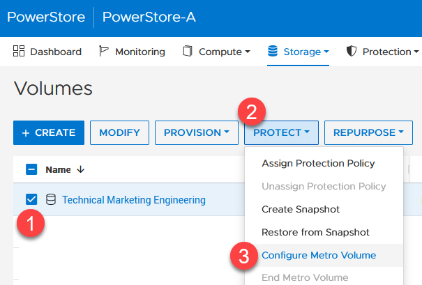
- Creating the metro volume session is a relatively simple process and involves a few clicks. Log into PowerStore Manager, select Storage, then select the volume (here, VMFS_Test-Demo), then select Configure Metro Volume.

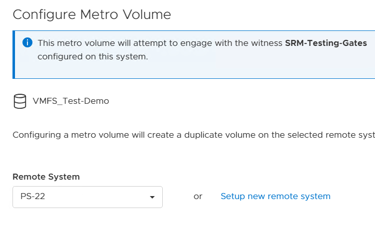
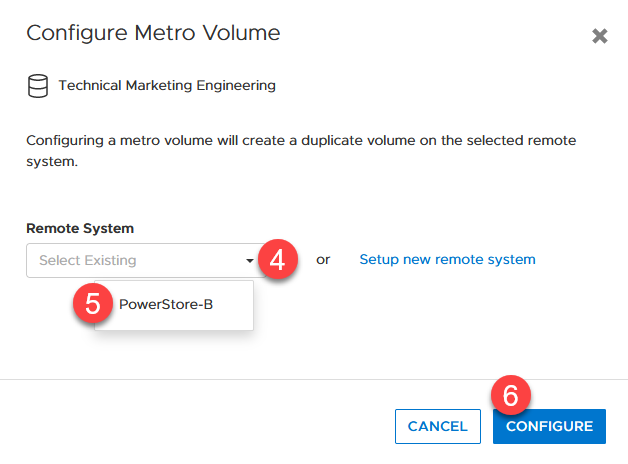
2. On the Configure Metro Volume page, select the remote PowerStore to create the duplicate volume.
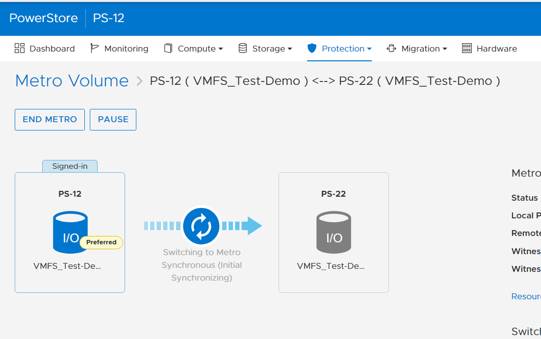
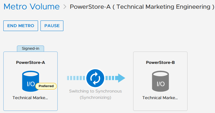
3. Now we see the volume switching to metro synchronous.
Creating the Metro Witness
Starting with PowerStore version 3.6, Metro Volume supports a witness server. The witness server is a third party that is installed on a stand-alone host. The witness observes the status of the local and remote PowerStore systems. When a failure occurs, the witness server determines which system remains accessible to hosts and continues to service I/Os. When configuring Metro Witness on a PowerStore appliance, you must generate a unique token.
Note: You must configure the witness on each PowerStore cluster.
1. The following is an example of using the generate_token.sh script to create the token JeBTPIFf:

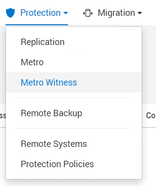
2. After gathering the token, select Protection > Metro Witness to enter the Metro witness configuration details.
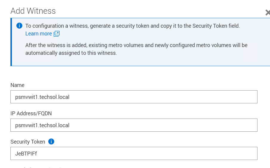
3. Enter the witness details, including the DNS or IP address and security token.
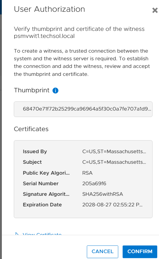
4. Confirm the witness settings.
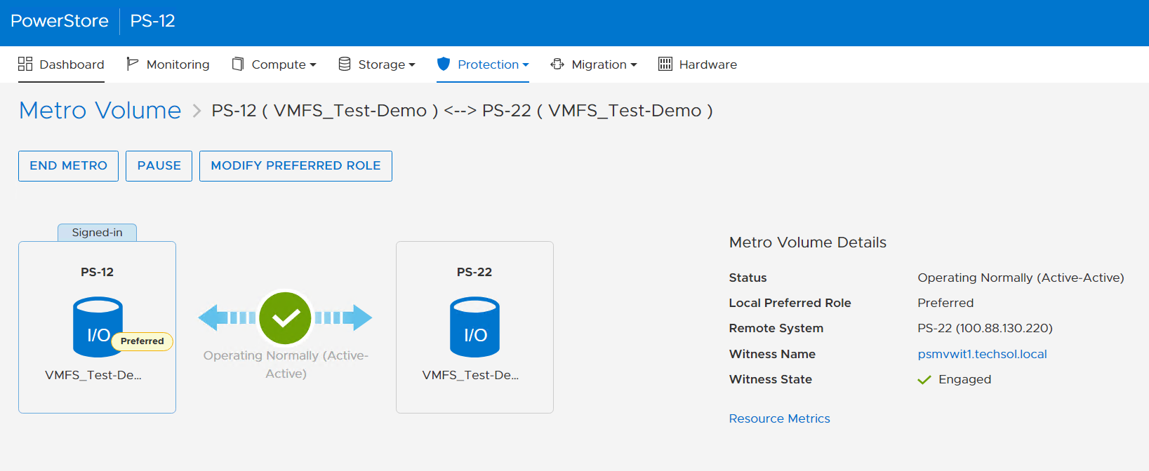
5. Witness is connected to the metro sessions.
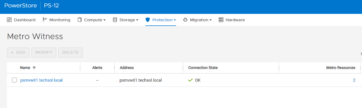
6. The metro session is synced, and the witness is now engaged.
Metro Volume is designed to give VMware environments the ability to operate synchronously without disruption. Metro Volume integrates seamlessly with vSphere Metro Storage Cluster, for our PowerStore customers who must avoid disaster/data unavailability.
For more information, see the following resources.
Resources
- White paper: Dell PowerStore: Metro Volume
- White paper: Dell PowerStore: Replication Technologies
Author: Jason Gates

Dell PowerStore – Easily Create a Metro Volume in Six Clicks
Thu, 04 May 2023 20:12:42 -0000
|Read Time: 0 minutes
In this short blog, I’ll walk you through the configuration of a metro volume and prove that it’s possible to enable a metro session in just six clicks, when the remote system and a standard volume are already setup.
A metro volume is a volume that runs a bi-directional synchronous replication between two different sites. Hosts using either side of a metro volume get active-active simultaneous access on both sides of the metro volume. The use case for a PowerStore metro volume is a vSphere Metro Storage Cluster (also known as a stretched cluster configuration) with VMware vSphere.
PowerStore metro volumes support a latency maximum of 5ms and a maximum distance of 80miles/100km. After the operator sets up a metro volume, PowerStore internally creates a metro session to control the replication between the two sites. When the remote system relationship is set up on PowerStore, and the volume is mapped to one or more hosts, it requires just six additional clicks to set up a metro session for a standard volume, as shown here:
1. Select the volume. 2. Navigate to PROTECT. 3. Select Configure Metro Volume.
|
|
4. Click the pull down to select the remote system. 5. Select the remote system. 6. Click CONFIGURE |
|
To mitigate any performance impact on the source system for the new, unsynchronized metro volume, PowerStore immediately starts with asynchronous replication and switches into synchronous replication once the data is in sync. |
|
Because a metro session replicates all IO synchronously, active-active host access is possible on both ends of the metro volume. Even during the initial synchronization, hosts can map the new volume on the replication destination but only get active paths when the metro session is in an active-active state.
|
|

When hosts are in a uniform configuration, active paths are provided by both participating PowerStore clusters. The following example shows a uniformly connected host that can access the metro volume in two storage networks (fabrics).
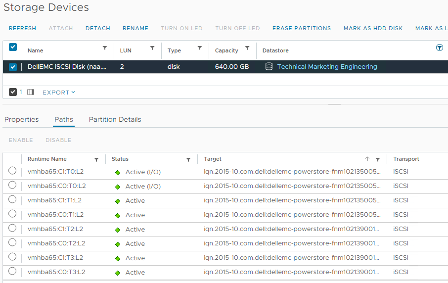
Here is the mapping of individual NICs in this example:
ESXi Host | NIC 1 | PowerStore-A | Node A Node B | C0:T0:L2 (Active I/O) C0:T1:L2 |
|
| PowerStore B | Node A Node B | C0:T2:L2 C0:T3:L2 |
| NIC2 | PowerStore-A | Node A Node B | C1:T0:L2 (Active I/O) C1:T1:L2 |
|
| PowerStore B | Node A Node B | C1:T2:L2 C1:T3:L2 |
Resources
Author: Robert Weilhammer, Principal Engineering Technologist
https://www.xing.com/profile/Robert_Weilhammer