


Dell PowerStore: vVol Replication with PowerCLI

Overview
In PowerStoreOS 2.0, we introduced asynchronous replication of vVol-based VMs. In addition to using VMware SRM to manage and control the replication of vVol-based VMs, you can also use VMware PowerCLI to replicate vVols. This blog shows you how.
To protect vVol-based VMs, the replication leverages vSphere storage policies for datastores. Placing VMs in a vVol storage container with a vSphere storage policy creates a replication group. The solution uses VASA 3.0 storage provider configurations in vSphere to control the replication of all individual configuration-, swap-, and data vVols in a vSphere replication group on PowerStore. All vVols in a vSphere replication group are managed in a single PowerStore replication session.
Requirements for PowerStore asynchronous vVol replication with PowerCLI:
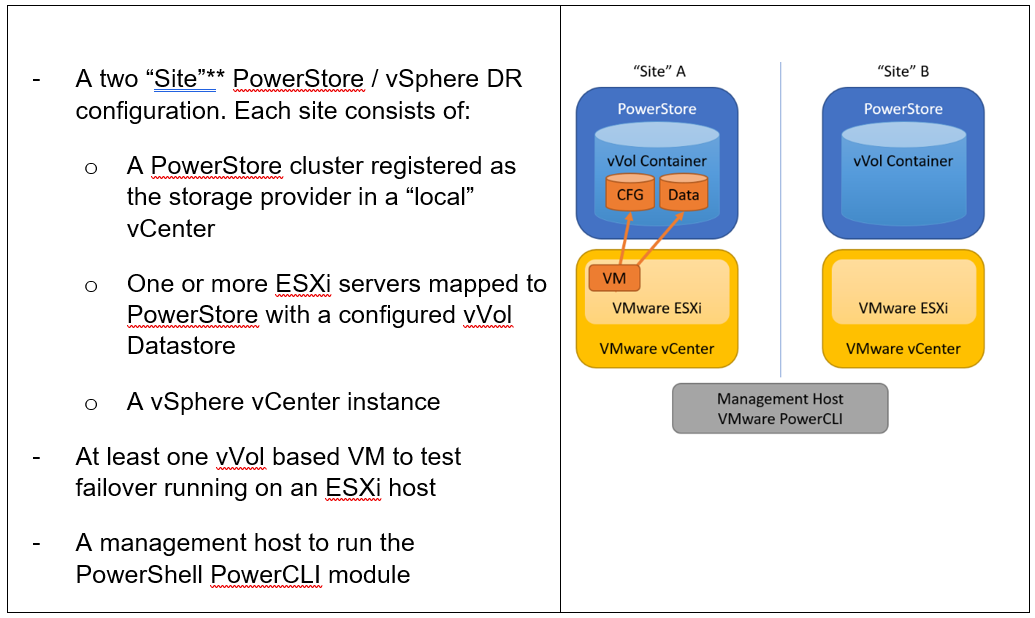
**As in VMware SRM, I’m using the term “site” to differentiate between primary and DR installation. However,
depending on the use case, all systems could also be located at a single location.
Let’s start with some terminology used in this blog.
PowerStore cluster | A configured PowerStore system that consists of one to four PowerStore appliances. |
PowerStore appliance | A single PowerStore entity that comes with two nodes (node A and node B). |
PowerStore Remote Systems (pair) | Definition of a relationship of two PowerStore clusters, used for replication. |
PowerStore Replication Rule | A replication configuration used in policies to run asynchronous replication. The rule provides information about the remote systems pair and the targeted recovery point objective time (RPO). |
PowerStore Replication Session | One or more storage objects configured with a protection policy that include a replication rule. The replication session controls and manages the replication based on the replication rule configuration. |
VMware vSphere VM Storage Policy | A policy to configure the required characteristics for a VM storage object in vSphere. For vVol replication with PowerStore, the storage policy leverages the PowerStore replication rule to set up and manage the PowerStore replication session. A vVol-based VM consists of a config vVol, swap vVol, and one or more data vVols. |
VMware vSphere Replication Group | In vSphere, the replication is controlled in a replication group. For vVol replication, a replication group includes one or more vVols. The granularity for failover operations in vSphere is replication group. A replication group uses a single PowerStore replication session for all vVols in that replication group. |
VMware Site Recovery Manager (SRM) | A tool that automates failover from a production site to a DR site. |
Preparing for replication
For preparation, similar to VMware SRM, there are some steps required for replicated vVol-based VMs:
Note: When frequently switching between vSphere and PowerStore, an item may not be available as expected. In this case, a manual synchronization of the storage provider in vCenter might be required to make the item immediately available. Otherwise, you must wait for the next automatic synchronization.
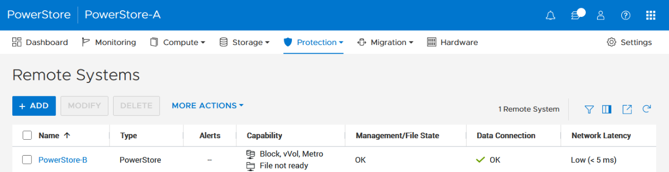
- Using the PowerStore UI, set up a remote system relationship between participating PowerStore clusters. It’s only necessary to perform this configuration on one PowerStore system. When a remote system relationship is established, it can be used by both PowerStore systems.
Select Protection > Remote Systems > Add remote system.
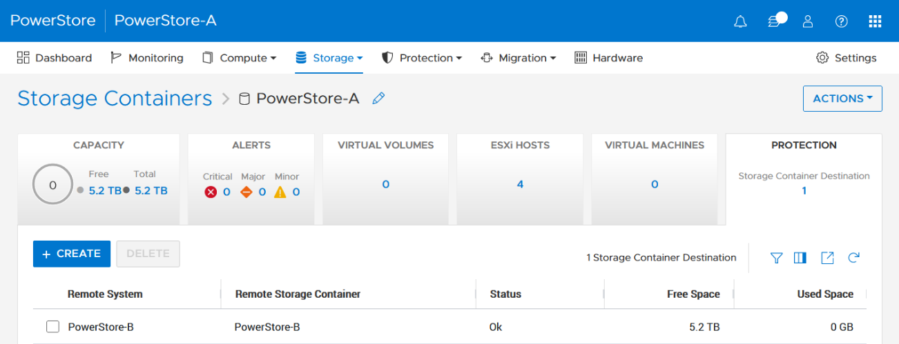
When there is only a single storage container on each PowerStore in a remote system relationship, PowerStoreOS also creates the container protection pairing required for vVol replication.
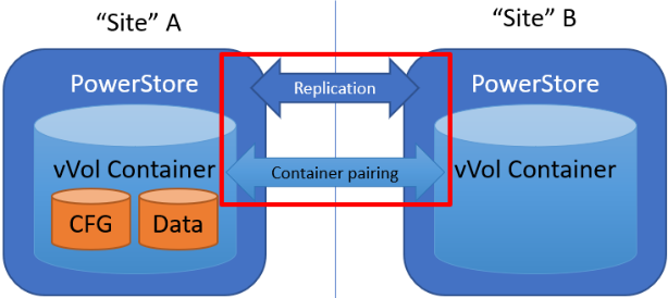
To check the configuration or create storage container protection pairing when more storage containers are configured, select Storage > Storage Containers > [Storage Container Name] > Protection.
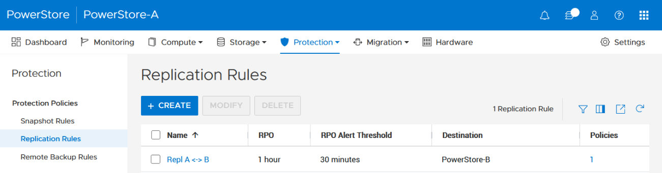
2. The VMware Storage Policy (which is created in a later step) requires existing replication rules on both PowerStoresystems, ideally with same characteristics. For this example, the replication rule replicates from PowerStore-A to PowerStore-B with a RPO of one hour, and 30 minutes for the RPO Alert Threshold.
Select Protection > Protection Policies > Replication Rules.
3. As mentioned in the Overview, VASA 3.0 is used for the communication between PowerStore and vSphere. If not configured already, register the local PowerStore in both vCenters as the storage provider in the corresponding vSphere vCenter instance.
In the vSphere Client, select [vCenter server] > Configuration > Storage Providers.
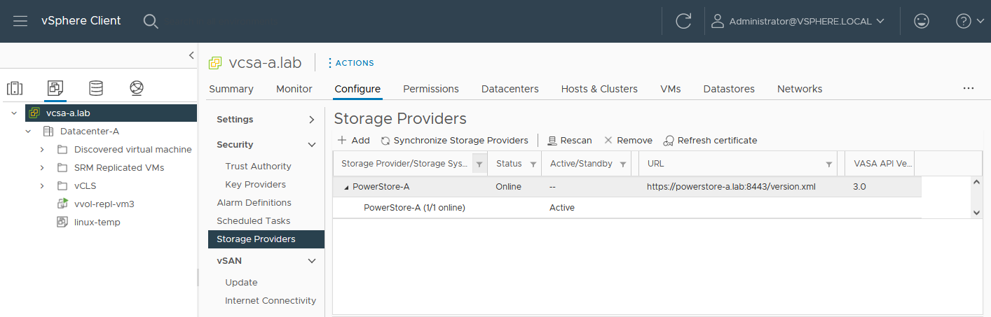
Use https://<PowerStore>:8443/version.xml as the URL with the PowerStore user and password to register the PowerStore cluster.
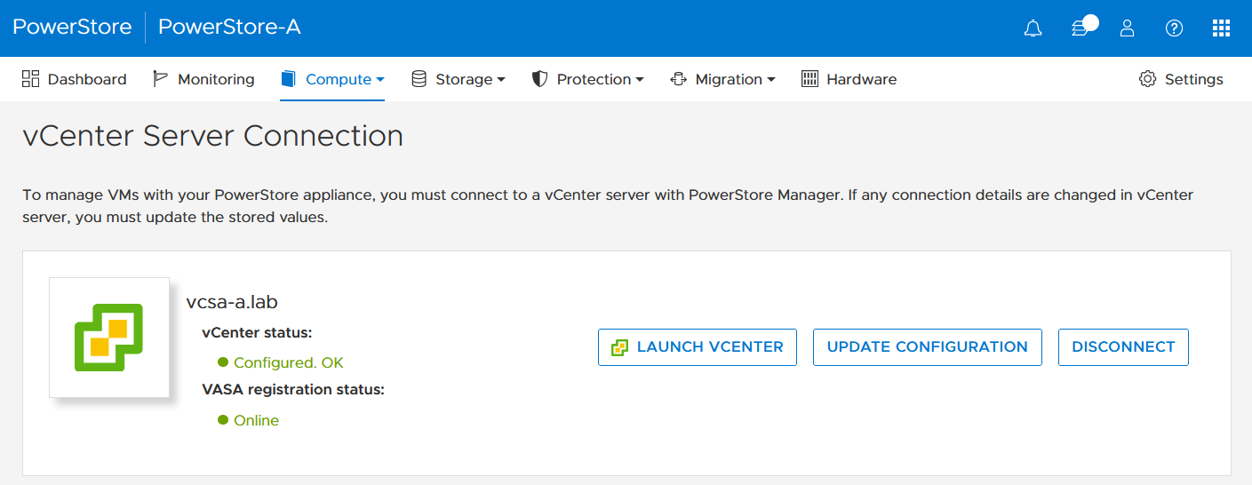
Alternatively, use PowerStore for a bidirectional registration. When vCenter is registered in PowerStore, PowerStoreOS gets more insight about running VMs for that vCenter. However, in the current release, PowerStoreOS can only handle a single vCenter connection for VM lookups. When PowerStore is used by more than one vCenter, it’s still possible to register a PowerStore in a second vCenter as the storage provider, as mentioned before.
In the PowerStore UI, select Compute > vCenter Server Connection.
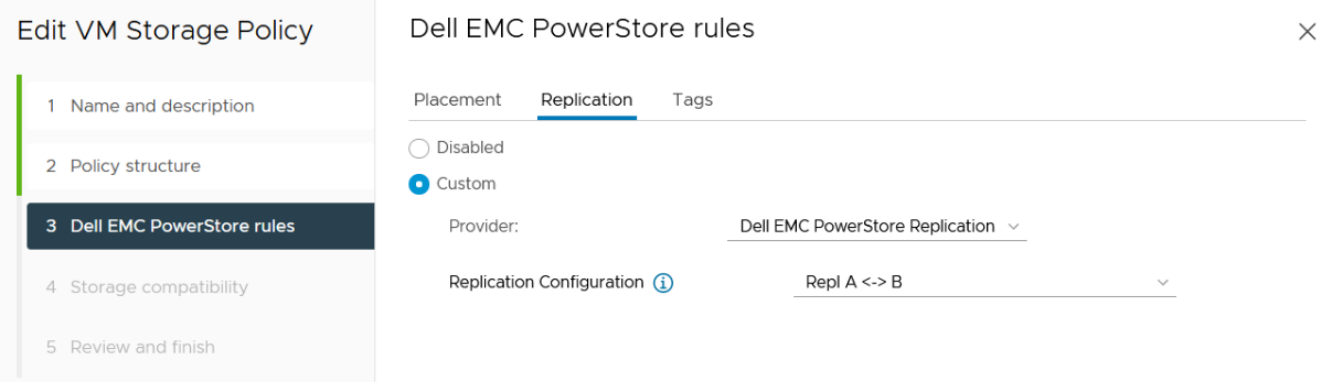
4. Set up a VMware storage policy with a PowerStore replication rule on both vCenters.
The example script in the section section Using PowerCLI and on myScripts4u@github requires the same Storage Policy name for both vCenters.
In the vSphere Client, select Policies and Profiles > VM Storage Policies > Create.
Enable “Dell EMC PowerStore” storage for datastore specific rules:
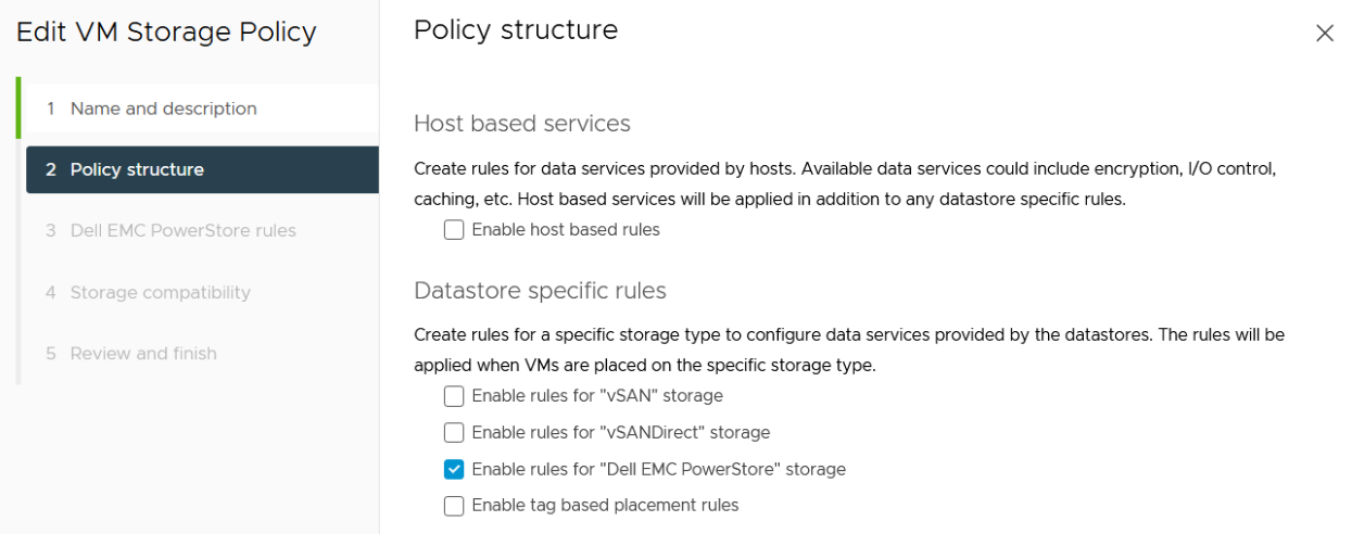
then choose the PowerStore replication rule:
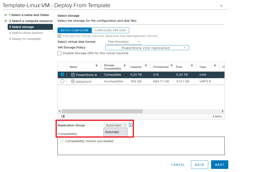
5. Create a VM on a vVol storage container and assign the storage protection policy with replication.
When a storage policy with replication is set up for a VM, you must specify a replication group. Selecting “automatic” creates a replication group with the name of the VM. Multiple VMs can be protected in one replication group.
When deploying another VM on the same vVol datastore, the name of the other replicated VM appears in the list for the Replication Group.
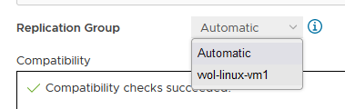
All vVol replication operations are on a Replication Group granularity. For instance, it’s not possible to failover only a single VM of a replication group.
That’s it for the preparation! Let’s continue with PowerCLI.
Using PowerCLI
Disclaimer: The PowerShell snippets shown below are developed only for educational purposes and provided only as examples. Dell Technologies and the blog author do not guarantee that this code works in your environment or can provide support in running the snippets.
To get the required PowerStore modules for PowerCLI, start PowerShell or PowerShell ISE and use Install-Module to install VMware.PowerCLI:
PS C:\> Install-Module -Name VMware.PowerCLI
The following example uses the replication group “vvol-repl-vm1”, which includes the virtual machines “vvol-repl-vm1” and “vvol-repl-vm2”. Because a replication group name might not be consistent with a VM to failover, the script uses the virtual machine name “vvol-repl-vm2” to get the replication group for failover.
Failover
This section shows an example failover of a vVol-based VM “vvol-vm2” from a source vCenter to a target vCenter.
1. Load modules, allow PowerStore to connect to multiple vCenter instances, and set variables for the VM, vCenters, and vCenter credentials. The last two commands in this step establishes the connection to both vCenters.
Import-Module VMware.VimAutomation.Core
Import-Module VMware.VimAutomation.Common
Import-Module VMware.VimAutomation.Storage
Set-PowerCLIConfiguration -DefaultVIServerMode 'Multiple' -Scope ([VMware.VimAutomation.ViCore.Types.V1.ConfigurationScope]::Session) -Confirm:$false  | Out-Null
$virtualmachine = "vvol-vm2"                   # Enter VM name of a vVol VM which should failover
$vcUser = 'administrator@vsphere.local'        # Change this to your VC username
$vcPass = 'xxxxxxxxxx'                         # VC password
$siteA = "vcsa-a.lab"                          # first vCenter
$siteB = "vcsa-b.lab"                          # second vCenter
Connect-VIServer -User "$vcUser" -Password "$vcPass" -Server $siteA -WarningAction SilentlyContinue
Connect-VIServer -User "$vcUser" -Password "$vcPass" -Server $siteB -WarningAction SilentlyContinue
2. Get replication group ($rg), replication group pair ($rgPair), and storage policy ($stoPol) for the VM. Because a replication group may have additional VMs, all VMs in the replication group are stored in $rgVMs.
$vm = get-vm $virtualmachine
# find source vCenter – this allows the script to failover (Site-A -> Site-B) and failback (Site-B -> Site-A)
$srcvCenter=$vm.Uid.Split(":")[0].Split("@")[1]
if ( $srcvCenter -like $siteA ) {
     $siteSRC=$siteA
     $siteDST=$siteB
} else {
     $siteSRC=$siteB
    $siteDST=$siteA
}
$rg = get-spbmreplicationgroup -server $siteSRC -VM $vm
$rgPair = Get-SpbmReplicationPair -Source $rg
$rgVMs=(Get-SpbmReplicationGroup -server $siteSRC -Name $rg| get-vm)
$stoPol = ( $vm | Get-SpbmEntityConfiguration).StoragePolicy.Name
3. Try a graceful shutdown of VMs in $rgVMs and wait ten seconds. Shut down VMs after three attempts.
$rgVMs | ForEach-Object {
     if ( (get-vm $_).PowerState -eq "PoweredOn")
     {
         stop-vmguest -VM $_ -confirm:$false -ErrorAction silentlycontinue | Out-Null
         start-sleep -Seconds 10
         $cnt=1
         while ((get-vm $_).PowerState -eq "PoweredOn" -AND $cnt -le 3 ) {
            Start-Sleep -Seconds 10
            $cnt++
         }
         if ((get-vm $_).PowerState -eq "PoweredOn") {
            stop-vm $_ -Confirm:$false  | Out-Null
         }
     }
}
4. It’s now possible to prepare and execute the failover. At the end, $vmxfile contains the vmx files that are required to register the VMs at the destination. During failover, a final synchronize before doing the failover ensures that all changes are replicated to the destination PowerStore. When the failover is completed, the vVols at the failover destination are available for further steps.
$syncRg = Sync-SpbmReplicationGroup -PointInTimeReplicaName "prePrepSync" -ReplicationGroup $rgpair.target
$prepareFailover = start-spbmreplicationpreparefailover $rgPair.Source -Confirm:$false -RunAsync
Wait-Task $prepareFailover
$startFailover = Start-SpbmReplicationFailover $rgPair.Target -Confirm:$false -RunAsync
$vmxfile = Wait-Task $startFailover
5. For clean up on the failover source vCenter, we remove the failed over VM registrations. On the failover target, we search for a host ($vmhostDST) and register, start, and set the vSphere Policy on VMs. The array @newDstVMs will contain VM information at the destination for the final step.
$rgvms | ForEach-Object {
     $_ | Remove-VM -ErrorAction SilentlyContinue -Confirm:$false
}
$vmhostDST = get-vmhost -Server $siteDST | select -First 1
$newDstVMs= @()
$vmxfile | ForEach-Object {
     $newVM = New-VM -VMFilePath $_ -VMHost $vmhostDST
     $newDstVMs += $newVM
}
$newDstVms | forEach-object {
     $vmtask = start-vm $_ -ErrorAction SilentlyContinue -Confirm:$false -RunAsync
     wait-task $vmtask -ErrorAction SilentlyContinue | out-null
     $_ | Get-VMQuestion | Set-VMQuestion -Option ‘button.uuid.movedTheVM’ -Confirm:$false

     $hdds = Get-HardDisk -VM $_ -Server $siteDST
     Set-SpbmEntityConfiguration -Configuration $_ -StoragePolicy $stopol -ReplicationGroup  $rgPair.Target | out-null
     Set-SpbmEntityConfiguration -Configuration $hdds -StoragePolicy $stopol -ReplicationGroup  $rgPair.Target | out-null
}
6. The final step enables the protection from new source.
start-spbmreplicationreverse $rgPair.Target  | Out-Null
$newDstVMs  | foreach-object {
    Get-SpbmEntityConfiguration -HardDisk $hdds -VM $_ | format-table -AutoSize
}
Additional operations
Other operations for the VMs are test-failover and an unplanned failover on the destination. The test failover uses the last synchronized vVols on the destination system and allows us to register and run the VMs there. The vVols on the replication destination where the test is running are not changed. All changes are stored in a snapshot. The writeable snapshot is deleted when the test failover is stopped.
Test failover
For a test failover, follow Step 1 through Step 3 from the failover example and continue with the test failover. Again, $vmxfile contains VMX information for registering the test VMs at the replication destination.
$sync=Sync-SpbmReplicationGroup -PointInTimeReplicaName "test" -ReplicationGroup $rgpair.target
$prepareFailover = start-spbmreplicationpreparefailover $rgPair.Source -Confirm:$false -RunAsync
$startFailover = Start-SpbmReplicationTestFailover $rgPair.Target -Confirm:$false -RunAsync
$vmxfile = Wait-Task $startFailover
It’s now possible to register the test VMs. To avoid IP network conflicts, disable the NICs, as shown here.
$newDstVMs= @()
$vmhostDST = get-vmhost -Server $siteDST | select -First 1
$vmxfile | ForEach-Object {
    write-host $_
    $newVM = New-VM -VMFilePath $_ -VMHost $vmhostDST
    $newDstVMs += $newVM
}
$newDstVms | forEach-object {
    get-vm -name $_.name -server $siteSRC | Start-VM -Confirm:$false -RunAsync | out-null # Start VM on Source
    $vmtask = start-vm $_ -server $siteDST -ErrorAction SilentlyContinue -Confirm:$false -RunAsync
    wait-task $vmtask -ErrorAction SilentlyContinue | out-null
    $_ | Get-VMQuestion | Set-VMQuestion -Option ‘button.uuid.movedTheVM’ -Confirm:$false
    while ((get-vm -name $_.name -server $siteDST).PowerState -eq "PoweredOff" ) {
        Start-Sleep -Seconds 5
    }
    $_ | get-networkadapter | Set-NetworkAdapter -server $siteDST -connected:$false -StartConnected:$false -Confirm:$false
}
After stopping and deleting the test VMs at the replication destination, use stop-SpbmReplicationFailoverTest to stop the failover test. In a new PowerShell or PowerCLI session, perform Steps 1 and 2 from the failover section to prepare the environment, then continue with the following commands.
$newDstVMs | foreach-object {
    stop-vm -Confirm:$false $_
    remove-vm -Confirm:$false $_
}
Stop-SpbmReplicationTestFailover $rgpair.target
Unplanned failover
For an unplanned failover, the cmdlet Start-SpbmReplicationFailover provides the option -unplanned which can be executed against a replication group on the replication destination for immediate failover in case of a DR. Because each infrastructure and DR scenario is different, I only show the way to run the unplanned failover of a single replication group in case of a DR situation.
To run an unplanned failover, the script requires the replication target group in $RgTarget. The group pair information is only available when connected to both vCenters. To get a mapping of replication groups, use Step 1 from the Failover section and execute the Get-SpbmReplicationPair cmdlet:
PS> Get-SpbmReplicationPair | Format-Table -autosize
Source Group Target Group
------------ ------------
vm1          c6c66ee6-e69b-4d3d-b5f2-7d0658a82292
The following part shows how to execute an unplanned failover for a known replication group. The example connects to the DR vCenter and uses the replication group id as an identifier for the unplanned failover. After the failover is executed, the script registers the VMX in vCenter to bring the VMs online.
Import-Module VMware.VimAutomation.Core
Import-Module VMware.VimAutomation.Common
Import-Module VMware.VimAutomation.Storage
$vcUser = 'administrator@vsphere.local'                # Change this to your VC username
$vcPass = 'xxxxxxxxxx'                                 # VC password
$siteDR = "vcsa-b.lab"                                 # DR vCenter
$RgTarget = "c6c66ee6-e69b-4d3d-b5f2-7d0658a82292"     # Replication Group Target – required from replication Source before running the unplanned failover
                                                       # to get the information run get-SpbmReplicationPair | froamt-table -autosize when connected to both vCenter
Connect-VIServer -User "$vcUser" -Password "$vcPass" -Server $siteDR -WarningAction SilentlyContinue
# initiate the failover and preserve vmxfiles in $vmxfile
$vmxfile = Start-SpbmReplicationFailover -server $siteDR -Unplanned -ReplicationGroup $RgTarget
$newDstVMs= @()
$vmhostDST = get-vmhost -Server $siteDR | select -First 1
$vmxfile | ForEach-Object {
    write-host $_
    $newVM = New-VM -VMFilePath $_ -VMHost $vmhostDST
    $newDstVMs += $newVM
}
$newDstVms | forEach-object {
    $vmtask = start-vm $_ -server $siteDST -ErrorAction SilentlyContinue -Confirm:$false -RunAsync
    wait-task $vmtask -ErrorAction SilentlyContinue | out-null
    $_ | Get-VMQuestion | Set-VMQuestion -Option ‘button.uuid.movedTheVM’ -Confirm:$false
}
To recover from an unplanned failover after both vCenters are back up, perform the following required steps:
- Add a storage policy with the previous target recovery group to VMs and associated HDDs.
- Shutdown (just in case) and remove the VMs on the previous source.
- Start reprotection of VMs and associated HDDs.
- Use Spmb-ReplicationReverse to reestablish the protection of the VMs.
Conclusion
Even though Dell PowerStore and VMware vSphere do not provide native vVol failover handling, this example shows that vVol failover operations are doable with some script work. This blog should give you a quick introduction to a script based vVol mechanism, perhaps for a proof of concept in your environment. Note that it would need to be extended, such as with additional error handling, when running in a production environment.
Resources
- GitHub - myscripts4u/PowerStore-vVol-PowerCLI: Dell PowerStore vVol failover with PowerCLI
- Dell PowerStore: Replication Technologies
- Dell PowerStore: VMware Site Recovery Manager Best Practices
- VMware PowerCLI Installation Guide
Author: Robert Weilhammer, Principal Engineering Technologist
https://www.xing.com/profile/Robert_Weilhammer
Related Blog Posts

Provision PowerStore Metro Volumes with Dell Virtual Storage Integrator (VSI)
Tue, 30 Aug 2022 19:55:24 -0000
|Read Time: 0 minutes
Since PowerStoreOS 3.0, native metro volumes have been supported for PowerStore in vSphere Metro Storage Cluster configurations. With the new Virtual Storage Integrator (VSI) 10.0 plug-in for vSphere, you can configure PowerStore metro volumes from vCenter without a single click in PowerStore Manager.
This blog provides a quick overview of how to deploy Dell VSI and how to configure a metro volume with the VSI plug-in in vCenter.
Components of VSI
VSI consists of two components—a VM and a plug-in for vCenter that is deployed when VSI is registered for the vCenter. The VSI 10.0 OVA template is available on Dell Support and is supported with vSphere 6.7 U2 (and later) through 7.0.x for deployments with an embedded PSC.
Deployment
A deployed VSI VM requires 3.7 GB (thin) or 16 GB (thick) space on a datastore and is deployed with 4 vCPUs and 16 GB RAM. The VSI VM must be deployed on a network with access to the vCenter server and PowerStore clusters. During OVA deployment, the import wizard requests information about the network and an IP address for the VM.
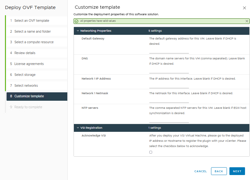
When the VM is deployed and started, you can access the plug-in management with https://<VSI-IP>.
Register VSI plug-in in vCenter
A wizard helps you register the plug-in in a vCenter. Registration only requires that you set the VSI Redis Password for the internal database and username/password.
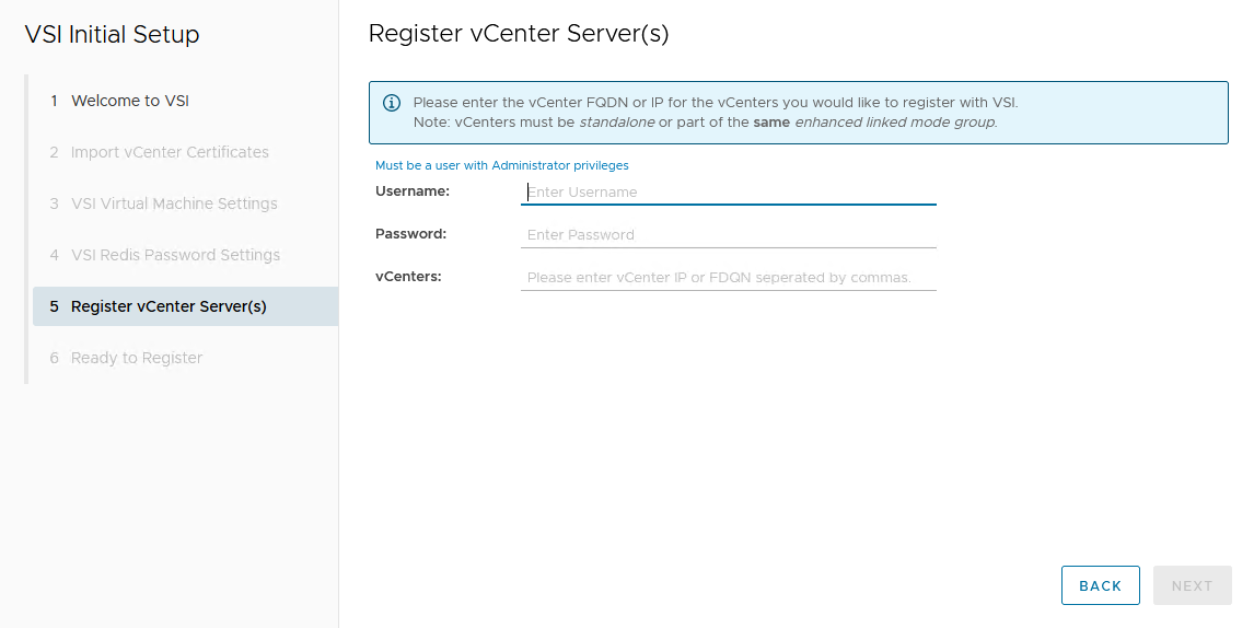
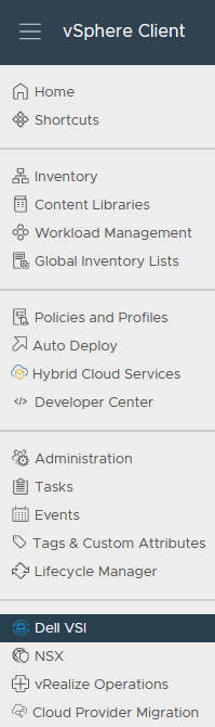
After the VSI VM is configured, it takes some time for the plug-in to appear in vCenter. You might be required to perform a fresh login to the vSphere Client before the Dell VSI entry appears in the navigation pane.
From the Dell VSI dashboard, use the + sign to add both PowerStore clusters used for metro volumes.
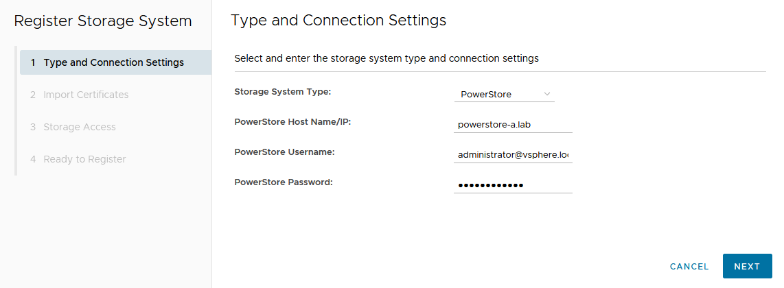
Configure a metro volume with the VSI plug-in
As with PowerStore Manager, creating a metro volume with the VSI plug-in requires three steps:
- Create and map a standard volume.
- Configure metro for the newly created volume.
- Map the second metro volume to the hosts.
The following example adds a new metro volume to cluster Non-Uniform, which already has existing metro volumes provisioned in a Non-Uniform host configuration. Esx-a.lab is local to PowerStore-A, and esx-b.lab is local to PowerStore-B.
- Create and map a standard volume in vSphere.
Use the Actions menu either for a single host, a cluster, or even the whole data center in vSphere. In this example, we chose Dell VSI > Create Datastore for the existing cluster Non-Uniform. - Configure metro for the newly created volume.
The VSI Create Datastore wizard leads us through the configuration.- For a metro volume, select the volume type VMFS.
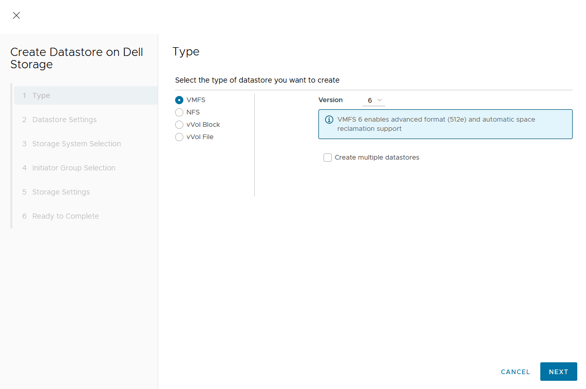
- Provide a name for the new volume.
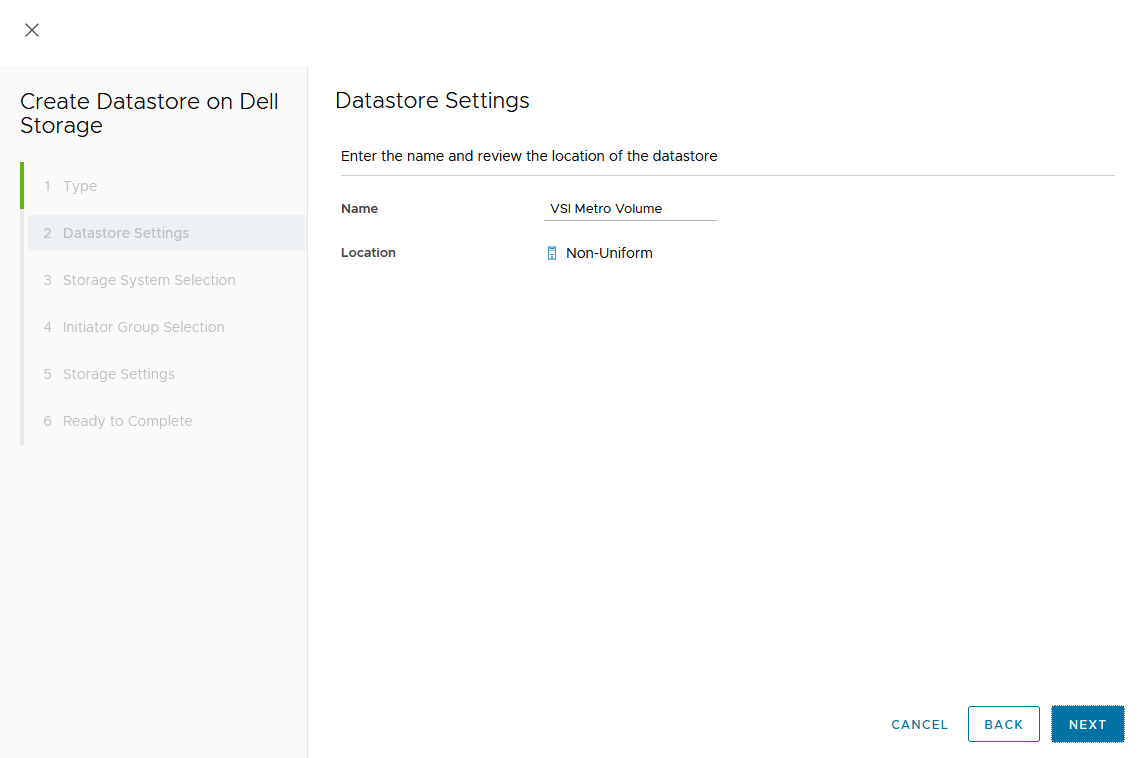
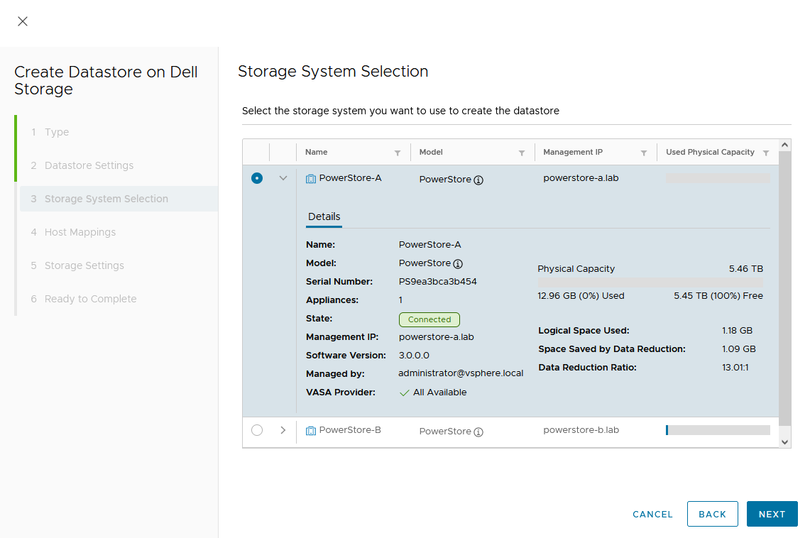
- Select the storage system.
- For a metro volume, select the volume type VMFS.
In the dialog box, you can expand the individual storage system for more information. We start with PowerStore-A for esx-a.lab.
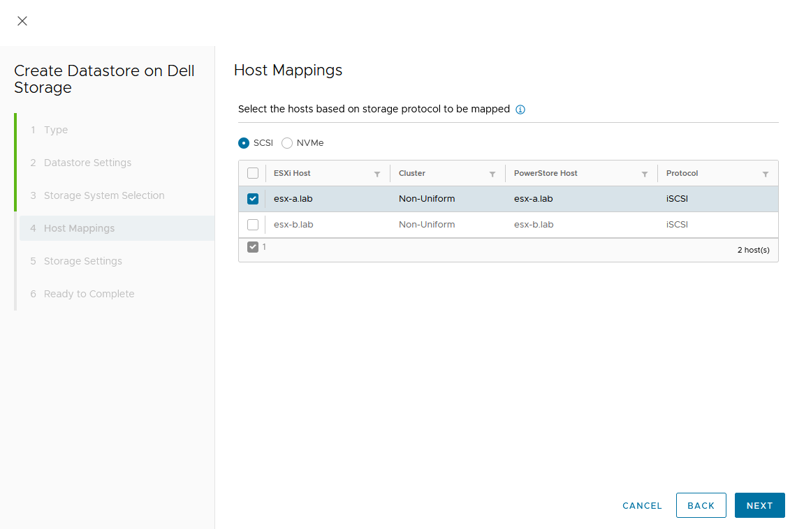
d. Map the host.
As this is a Non-Uniform cluster configuration, only esx-a.lab is local to PowerStore-A and should be mapped to the new volume on PowerStore-A.
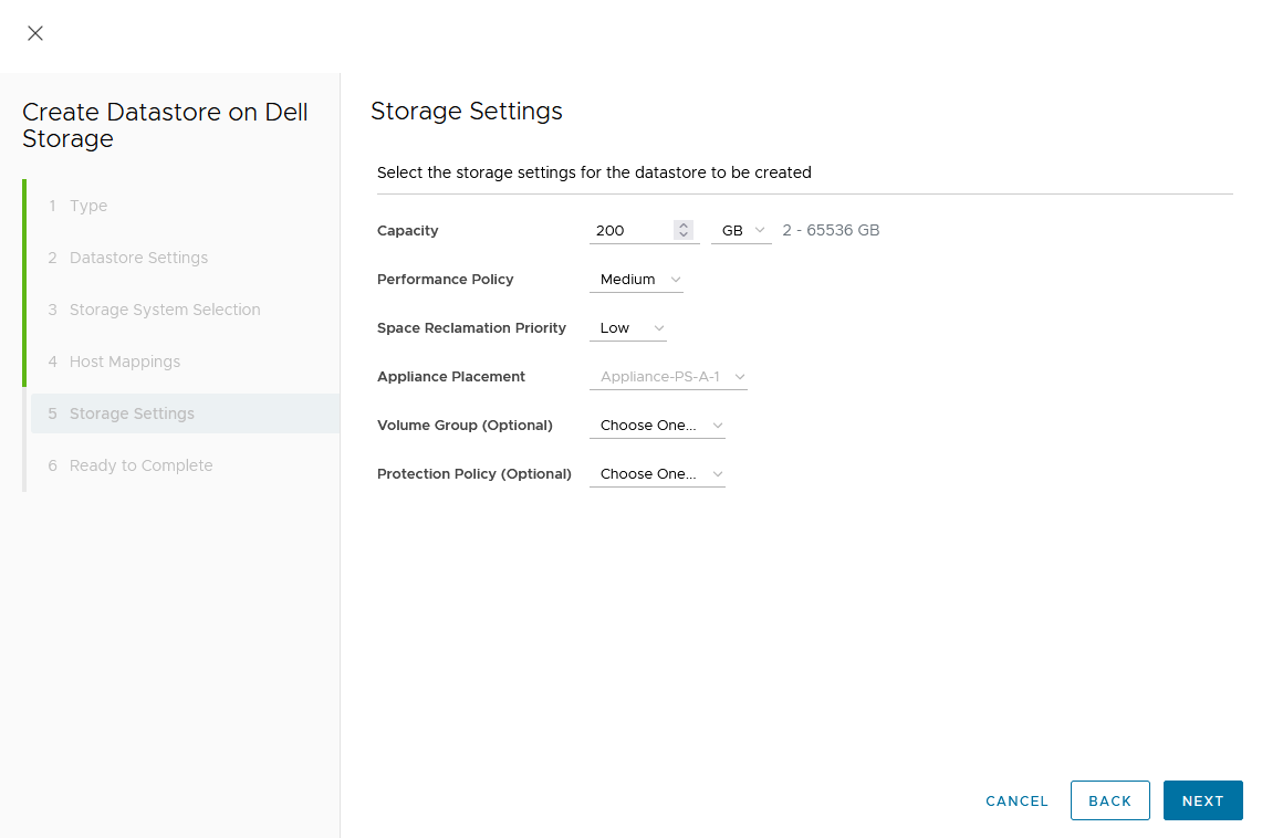
e. Set a Capacity and select other volume settings such as Performance Policy or Protection Policy.
Wizard summary page:
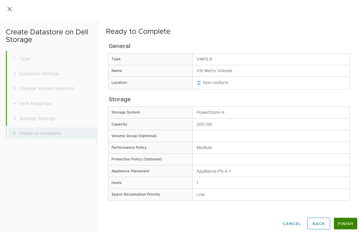
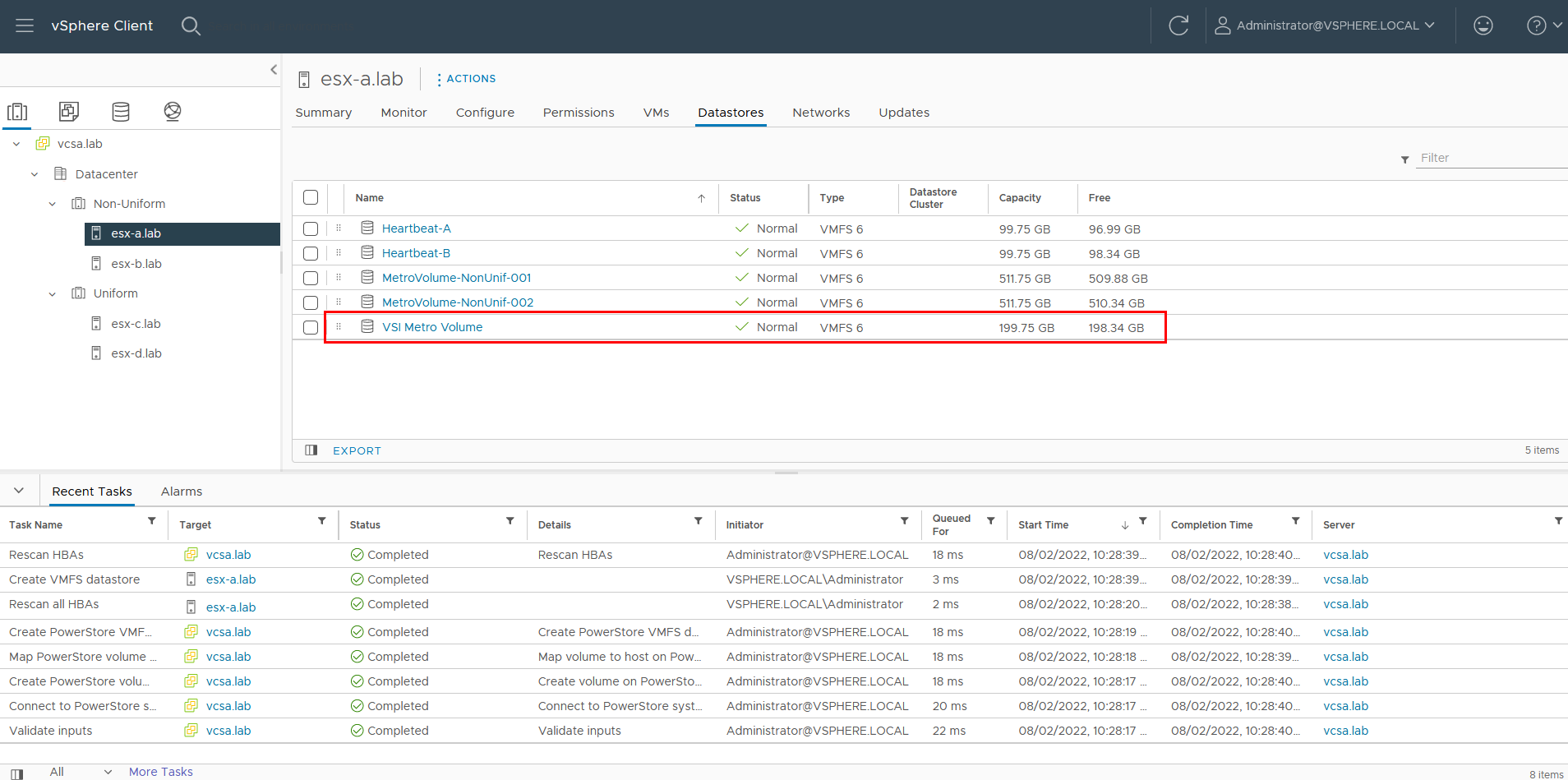
Upon completion, the volume is configured and mapped to the host. The following screenshot shows the new volume, VSI Metro Volume, and the tasks that ran to create and map the volume in vSphere.
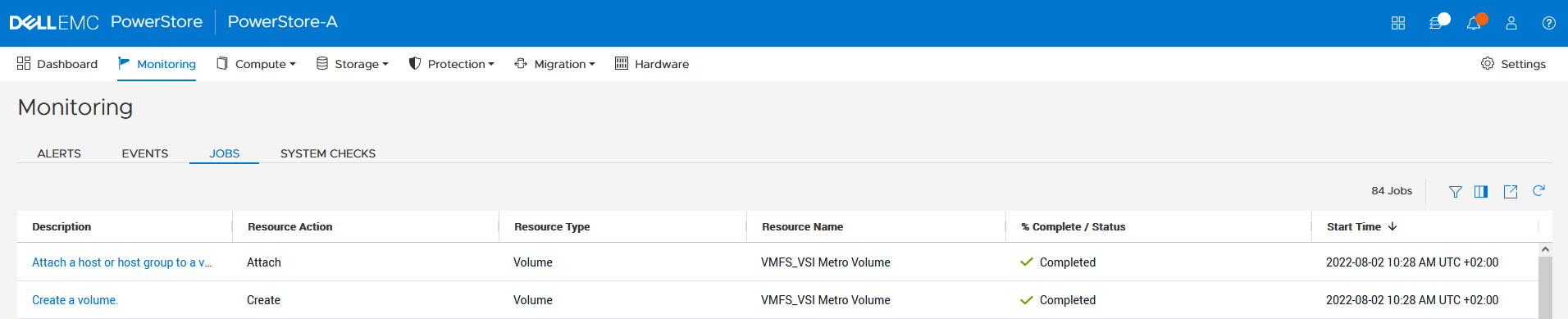
For reference, the related jobs in PowerStore Manager for PowerStore-A are also available at Monitoring > Jobs:
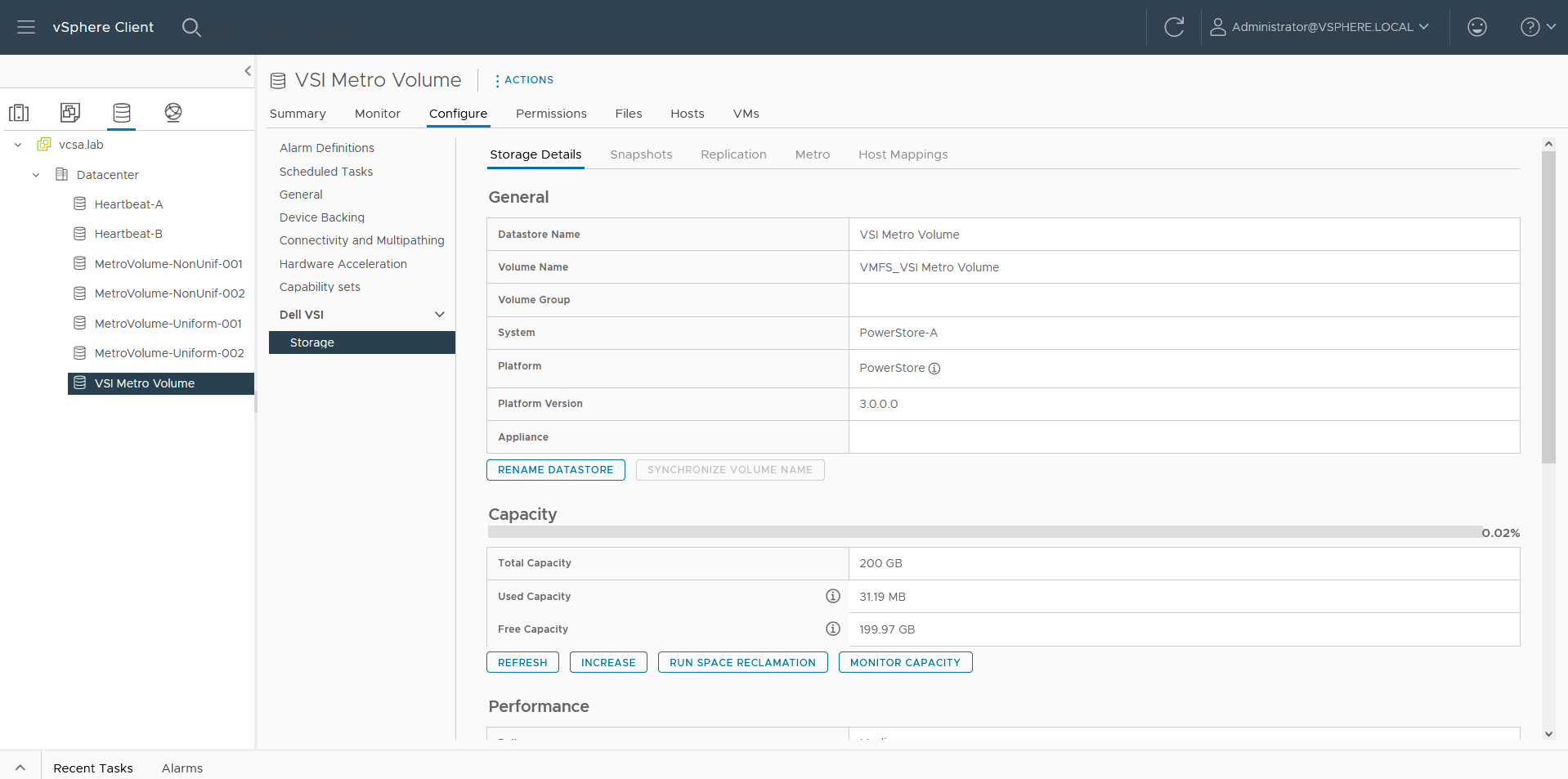
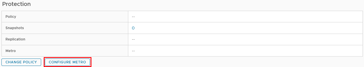
f. Select the VSI Metro Volume datastore, and then select Configure > Dell VSI > Storage to see the details for the backing device.
g. On the Storage Details tab under Protection, click Configure Metro.
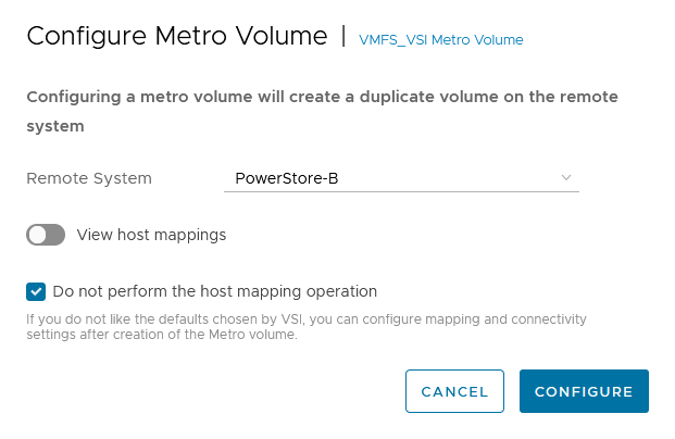
h. In the Configure Metro Volume dialog box, specify the Remote System and whether host mapping should be performed.
Depending on host registrations on PowerStore, automatic mapping may be unwanted and can be skipped. In this example, PowerStore-B has also the esx-a.lab host registered to provide access to one of the heartbeat volumes required for vSphere HA. The host mapping operation in the Create Datastore wizard creates an unwanted mapping of the volume from PowerStore-B to esx-a.lab. To configure manual mapping after the metro volume is created, select Do not perform the host mapping operation.
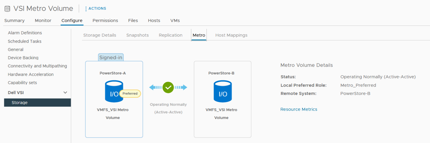
The metro volume is immediately configured on PowerStore and the Metro tab in Dell VSI > Storage view shows the status for the metro configuration.
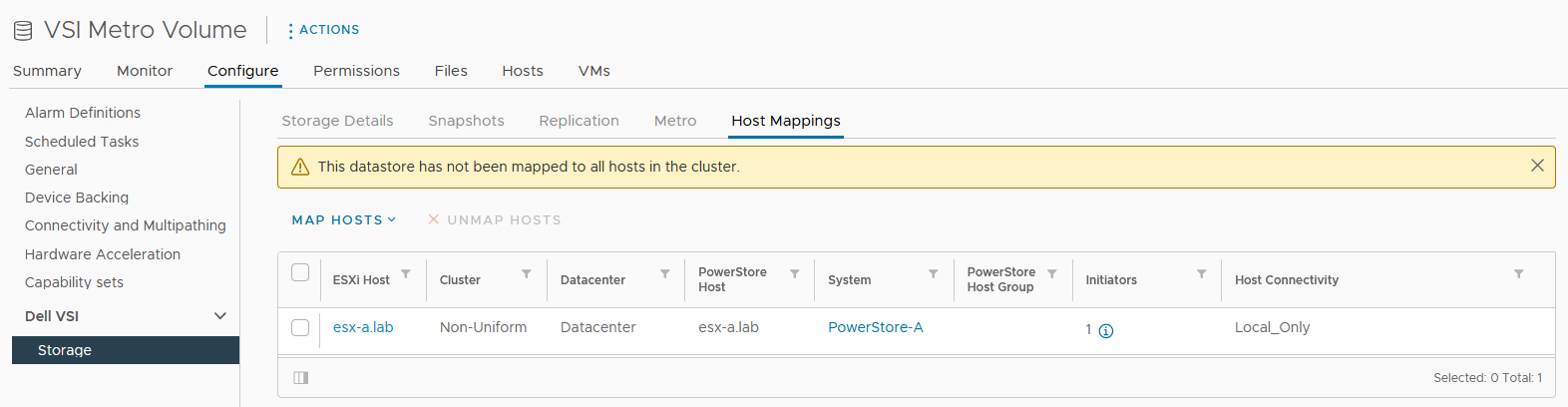
3. Map the second metro volume to the host.
Because we skipped host mapping when we created the metro volume, we must map the esx-b.lab host to the metro volume on PowerStore-B on the Host Mappings tab. Currently, the volume is only mapped from PowerStore-A to esx-a.lab.
a. Select Map Hosts > PowerStore-B to open the Map Hosts dialog box.
b. Map the volume on PowerStore-B for esx-b.lab.
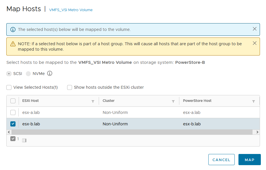
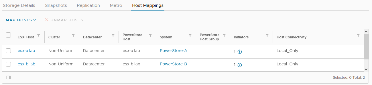
The host mapping overview shows the result and concludes the metro volume configuration with Virtual Storage Integrator (VSI) plugin.
Resources
- Dell Virtual Storage Integrator (VSI) for VMware vSphere Client Version 10.0 Product Guide
- Dell PowerStore Protecting Your Data—Metro Protection
- Dell PowerStore: Metro Volume
Author: Robert Weilhammer, Principal Engineering Technologist
https://www.xing.com/profile/Robert_Weilhammer

Intro to Native Metro Volume Support with a PowerStore CLI Example
Wed, 27 Jul 2022 13:50:50 -0000
|Read Time: 0 minutes
Introduction
With native metro volume support, PowerStoreOS 3.0 introduces an additional feature that helps prevent your production from outages caused by a failure in your VMware vSphere Metro Storage Cluster (vMSC) environment. The Metro Volume feature is available at no additional cost on PowerStore and can be used to protect VMFS datastores.
A vMSC configuration is a stretched cluster architecture where ESXi hosts can be in two different sites in metro distance (100 km / 60 miles) while accessing a synchronously replicated storage resource. The PowerStore Metro Volume feature provides concurrent and full active/active host IO on both participating PowerStore cluster configurations.
Although this adds additional latency, a PowerStore Metro Volume ensures that all host I/O is committed on both mirror volumes of a Metro Volume before the host receives an acknowledgement for the write I/O. To survive a disaster with minimal, or even better, no interruption to your production, PowerStore has built in a mechanism to protect your data from a split-brain situation in case of a failure or disaster. PowerStore is designed to allow only active-active workloads on both sides of a Metro Volume when data can be replicated between the Metro Volume mirrors on both PowerStore clusters.
From a topology point of view, PowerStore supports two different configuration scenarios. There is a Non-Uniform configuration where hosts only have access to the local PowerStore system: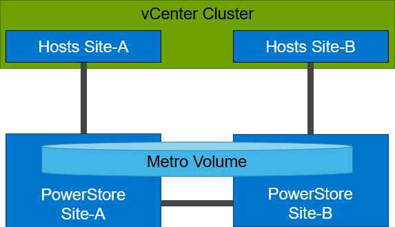
There is also a Uniform configuration where hosts can access both the local and remote PowerStore.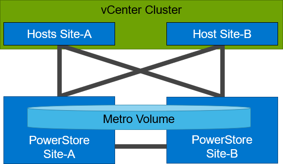
Even though they look similar, the benefits of the different topologies are in the details.
A Non-Uniform host configuration reduces complexity because it requires less configuration and only provides local access to the volume that has the least utilization on the link between the two sites. However, in a failure situation with the local PowerStore array, or during a link failure, local hosts can lose access to the Metro Volume. In this situation, VMware HA needs to restart any VMs on the affected datastore using the surviving hosts on the opposite site. There should be sufficient host resources available on each site to allow running the most critical VMs while the peer site is not available.
In a Uniform host configuration, the hosts have additional links to the remote PowerStore cluster that can be used during a failure situation. If the Metro Volume is not accessible on the local PowerStore cluster due a failure or link outage, the hosts can utilize the cross links to access the volume on the remote site. In this scenario, a VM could survive the failure because hosts can switch the working path to the remote system. Under normal operations, the host I/O should be kept within the local site to avoid unnecessary bandwidth utilization on the link between the sites for the workload and to minimize latency.
Let me show you a quick example where we assume a theoretical local latency of 0.5ms and 2ms between the sites.
1. The host is using a link to the local array as primary path to write to a Metro Volume. The theoretical latency for the I/O would be as follows:
- 0.5ms workload from the host to the local storage
- 2.0ms to replicate the workload to the remote storage. Workload uses a link between the sites.
- 2.0ms to receive the commit from the remote storage on the local storage
- 0.5ms for the commit to the host
In total, we would see a 5.0ms latency for the I/O and the workload is sent only once across the link between the sites for replication (A-B).
2. When the host is using the links to the remote array as primary path, we would see following situation:
- 2.0ms to send the workload to the remote storage. The workload uses a link between the sites.
- 2.0ms to replicate the workload to a peer. The workload uses a link between the sites.
- 2.0ms for the commit from the peer array to the remote storage
- 2.0ms for the commit to the host
In total, we would see a theoretical latency of 8.0ms for the same I/O because the workload and commits are always utilizing the link between the sites: once, when host writes data to the remote array (A to B), and again when the write is replicated to peer storage (B-A) plus the required commits.
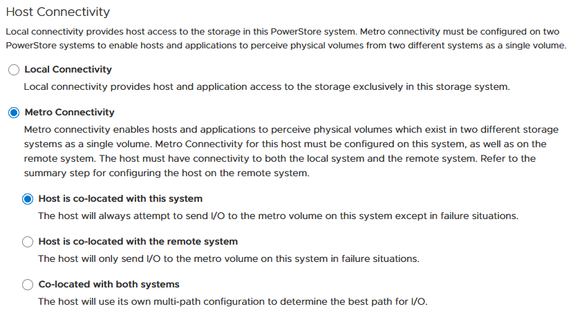
To ensure the selection of optimal paths, PowerStore provides information for optimal path selection using the Asynchronous Logical Unit Access (ALUA) protocol. For the correct ALUA state, uniform hosts must be registered with their local or remote relation to each PowerStore cluster. There are four options when registering a host in PowerStore Manager:
- Local only – Used for Non-Uniform Metro Volumes and hosts serving only standard volumes.
- Host Co-Located with this PowerStore system – Indicates that the host is local (low latency) to the PowerStore, and should get the ALUA active/optimized paths.
- Host Co-Located with remote PowerStore system – Indicates that the host is a remote host (high latency), and host should get ALUA active/non-optimized paths.
- Host is Co-Located with both – Indicates that all hosts and PowerStore clusters are located in the same location with the same latency.
When a host is configured with a metro connectivity option for Uniform Metro Volume, PowerStore provides default ALUA path information for non-metro volumes standard volumes.
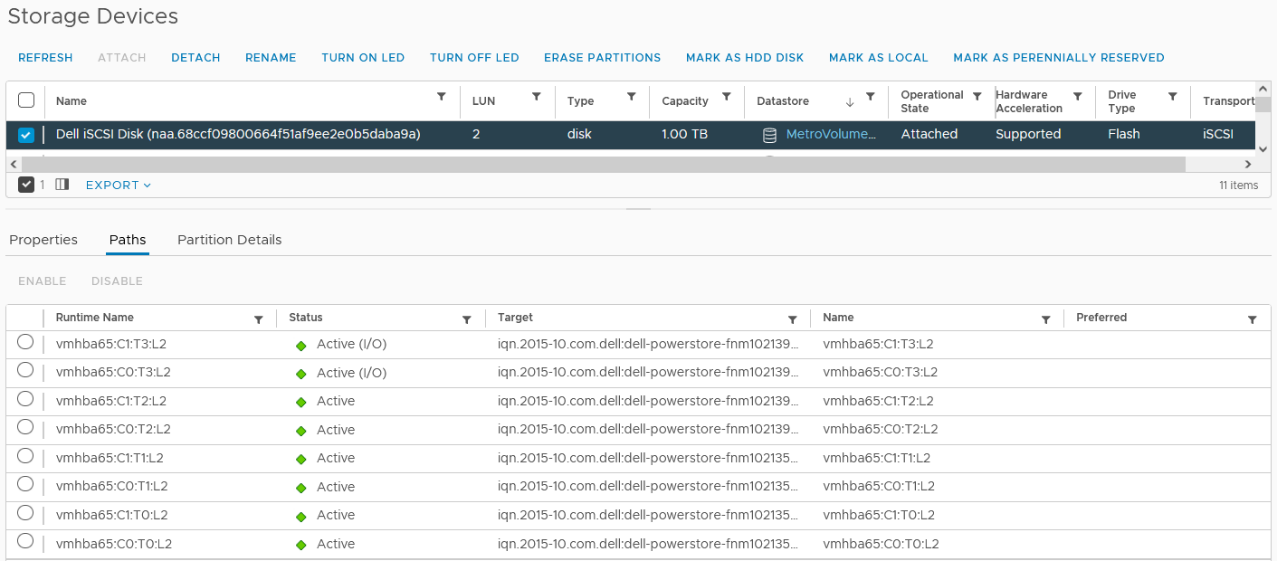
With Native Multipathing’s (NMP) default path selection policy (PSP) of “round robin” (RR), the connected ESXi hosts use the provided ALUA path information to determine the optimal working path down to the volume. When more than one active/optimized path is available, ESXi PSP round robin measures the latency to the volume to select the most optimal working path. The current working path is indicated with the status “Active (I/O)” in vCenter, while other paths only show the status “Active”. The following figure shows the path states for an ESXi host in a Uniform host configuration after a Metro Volume configuration is finished.
After hosts are set up in PowerStore manager, we can start to configure a Metro Volume. This is possible in just a few steps on a single PowerStore cluster:
- To set up a Remote Systems relationship with the peer PowerStore, select Protection > Add Remote System.
- Use the Add Volume wizard to create and map a standard volume.
- In the Volumes page, configure a Metro Volume with six clicks.
a. Select the new volume.
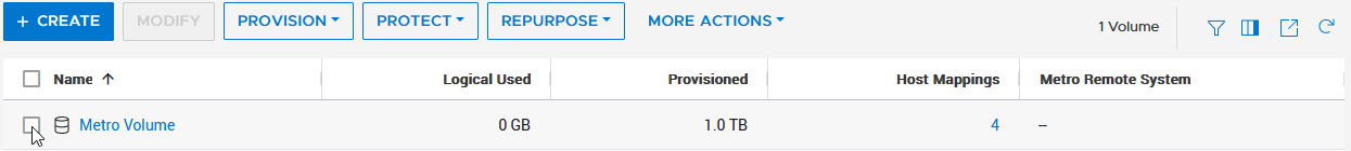
b. Click Protect.
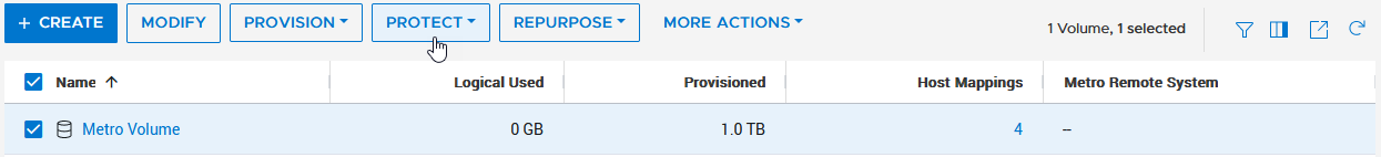
c. Configure Metro Volume
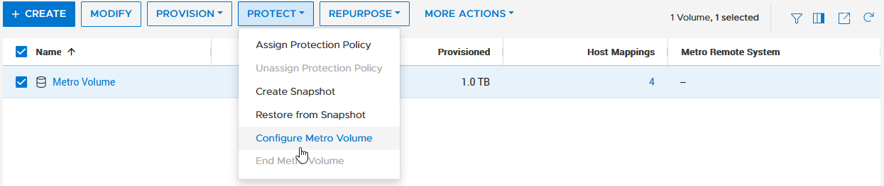
d. Click on the Remote System pull down.
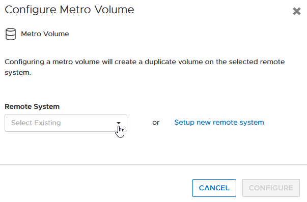
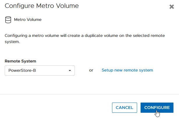
e. Select an existing remote system (or set up a new remote system relationship with another PowerStore cluster).
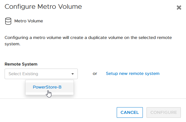
f. Click configure to start the configuration.
4. On the peer PowerStore cluster, map the new Metro Volume to the hosts.
5. Use the new Metro Volume to create a VMFS datastore.
Aside from using PowerStore Manager, it’s also possible to use the PowerStore REST API or the PowerStore CLI to set up a Metro Volume in just a few steps. In this blog, I want to show you the required steps in a PowerStore CLI session (pstcli -d <PowerStore> -session) to set up Metro Volume on PowerStore on a configured pair of PowerStore systems (as shown in the previous figure) for uniform host connectivity:
1. On PowerStore Manager PowerStore-A
a. Create Remote Systems relationship:
x509_certificate exchange -service Replication_HTTP -address <IP-Address PowerStore-B> -port 443 -username admin -password <YourSecretPassword>
 remote_system create -management_address <IP-Address PowerStore-B> -management_port 443 -remote_username admin -remote_password <YourSecretPassword> -type PowerStore -data_network_latency Low
b. Register ESXi hosts for Uniform host connectivity:
host create -name esx-a.lab -os_type ESXi -initiators -port_name iqn.1998-01.com.vmware:esx-a:<…>:65 -port_type iSCSI -host_connectivity Metro_Optimize_Local
host create -name esx-b.lab -os_type ESXi -initiators -port_name iqn.1998-01.com.vmware:esx-b:<…>:65 -port_type iSCSI -host_connectivity Metro_Optimize_Remote
c. Prepare and map a standard volume:
volume create -name MetroVolume-Uniform -size 1T
volume -name MetroVolume-Uniform -attach esx-a.lab
volume -name MetroVolume-Uniform -attach esx-b.lab
d. Configure the volume as a Metro Volume:
volume -name MetroVolume-Uniform configure_metro -remote_system_name PowerStore-B
2. On PowerStore Manager PowerStore-B
a. Register ESXi hosts for Uniform host connectivity:
host create -name esx-a.lab -os_type ESXi -initiators -port_name iqn.1998-01.com.vmware:esx-a:<…>:65 -port_type iSCSI -host_connectivity Metro_Optimize_Remote
host create -name esx-b.lab -os_type ESXi -initiators -port_name iqn.1998-01.com.vmware:esx-b:<…>:65 -port_type iSCSI -host_connectivity Metro_Optimize_Local
b. Map Volume to ESXi hosts:
volume -name MetroVolume-Uniform -attach esx-a.lab
volume -name MetroVolume-Uniform -attach esx-b.lab
c. Monitor Metro Volume (optional):
replication_session show -query type=Metro_Active_Active -select state,progress_percentage,data_transfer_state
3. In vCenter
a. Rescan the SCSI bus.
b. Configure the VMFS datastore with the new Metro Volume.
For more information, see the following resources.
Resources
- vSphere Metro Storage Cluster (vMSC)
- White paper: Dell PowerStore: Metro Volume
- White paper: Dell PowerStore: Replication Technologies
Author: Robert Weilhammer, Principal Engineering Technologist