
Blogs
Short articles that discuss data center networking solutions

Virtualization with Layer 2 over Layer 3
Tue, 28 Mar 2023 12:49:05 -0000
|Read Time: 0 minutes
IT organizations must transform to meet the increasingly complex challenges in data center networking. Virtualization and software-defined data center (SDDC) in hyperconverged services are key components for today's data centers.
IT organizations making this transformation must interconnect their data centers. Virtualization and other high-value services are creating the need for logically connected, geographically isolated data centers. Dell Technologies has the infrastructure architectures to facilitate these requirements.
With Dell SmartFabric OS10 operating system, Dell introduces a networking solution in virtualization with two popular VLAN tunneling technologies: virtual extensive LAN (VXLAN) and generic routing encapsulation (GRE).
The solution of Border Gateway Protocol (BGP) and Ethernet Virtual Private Network (EVPN) for VXLAN uses Dell PowerSwitches and PowerEdge servers. BGP EVPN for VXLAN serves as a network virtualization overlay to extend Layer 2 connectivity across the data centers, which simplifies the deployment of virtualization and provides benefits such as vMotion, vSAN, and overall efficient resource sharing.
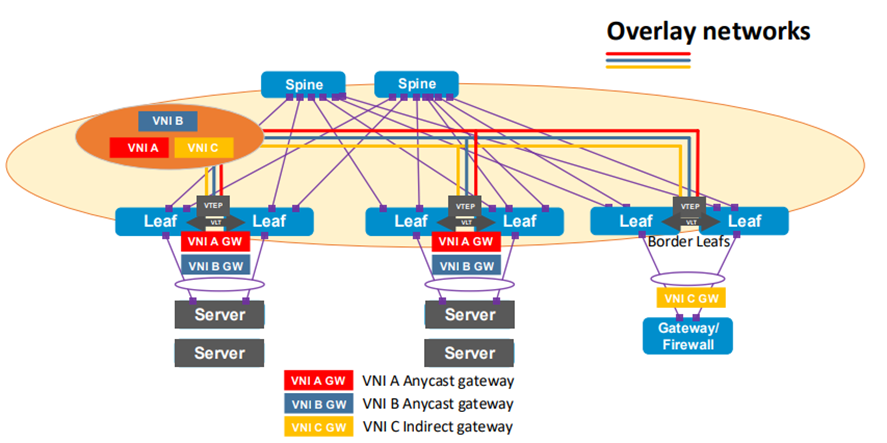
Figure 1. BGP EVPN for VXLAN network diagram overview
GRE is an IP encapsulation protocol that transports IP packets over a network in a point-to-point interconnection between two branches by tunneling any Layer 3 protocol, including IP.
With BGP EVPN VXLAN and GRE, any organization can interconnect their data centers across public internet in a secure (encrypted) manner. For example, data centers can securely connect over a local connection network—even if they are geographically distant or in different countries. The following figure illustrates that changing the infrastructure to leverage the existing Dell products portfolio on the production environment (VxRail, PowerStore, and PowerFlex) does not impact performance.
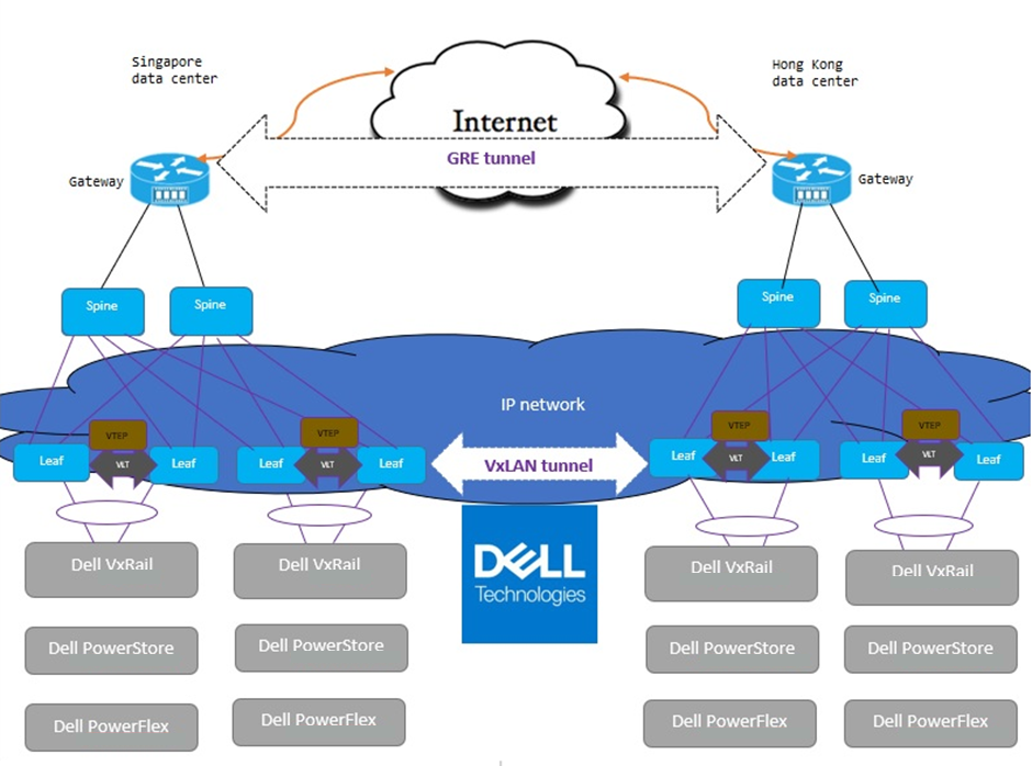
Figure 2. Data center interconnection over public internet with BGP EVPN for VXLAN and GRE tunneling
BGP EVPN for VXLAN and GRE tunneling provides the following benefits:
- Increases scalability in virtualized cloud environments
- Optimizes existing infrastructure with virtualization, scalability, flexibility, and mobility across data centers
- Maintains the security of the data center
Contact Dell Technologies for more details on this solution. Dell Technologies is excited to partner with you to deliver high-value services for your business.
Resources
For more information, refer to the following sections of the VMware Cloud Foundation on VxRail Multirack Deployment Using BGP EVPN Configuration and Deployment Guide:
Routing on the Host - Essential to the Scalable Data Center
Tue, 13 Dec 2022 18:04:10 -0000
|Read Time: 0 minutes
Routing on the Host (RoH) is a natural next step for data center operators who have adopted IP BGP in their switch stacks. They have adapted the pure Layer 3 fabric pioneered by web-scale operators to work in their networks. Border Gateway Protocol (BGP) has proven to be the ideal routing protocol for the IP fabric because it is mature, ubiquitous, and feature rich. The next step is to implement RoH and use IP BGP in the connection from the server (host) interface to the leaf switch port, where the rubber hits the road.
BGP can be simplified by developing a suitable routing protocol design and establishing standard configuration patterns to enact the design. All personnel involved with configuration must understand how BGP works and is configured. Dell data center switches running Dell SmartFabric OS10 provide a robust platform to run RoH with a Layer 3 BGP fabric.
In this blog, we consider benefits of RoH, including improved scalability, flexibility, and performance with some use cases. For additional details about RoH, also known as routing to the host, see the blog Do I Need Layer 2 Switching?.
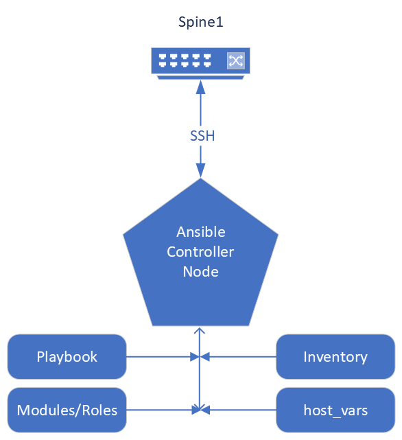
Figure 1 illustrates RoH with BGP. This example consists of a Dell switch fabric running Dell SmartFabric OS10 configured for Layer 3 point-to-point links and exterior BGP as the routing protocol. The host is a server with a bare metal installation of Linux. The host is running FRRouting (FRR), an open-source routing stack configured for BGP. Note that the host and switch ports are only configured for Layer 3 BGP networking.
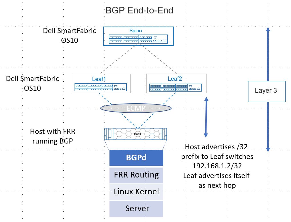
Figure 1. Routing to the Host Supported by Dell SmartFabric OS10 BGP
Scalability
A data center design must facilitate scaling out (horizontally) to accommodate additional workloads quickly and with minimal impact on network operations. Routing on the host facilitates scaling out.
Consider a use case of a customer with a multi-site data center in Figure 2 on the right. Operations requires scaling out compute (horizontally) to increase website capacity. Site 1 is resource-constrained, meaning Spine 4, Leaf 7 and Leaf 8, and associated hosts will be added to Site 2. The hosts and leaf switch ports to the hosts will be configured for Layer 3 BGP. At cutover, the switches communicate via BGP, and new routes converge. The new hosts advertise their presence using BGP. The whole network becomes aware of the new hosts and the applications can now run. Routing to the host and BGP has enabled a quick scale-out. The retirement of hosts can also happen with minimal effects through BGP convergence.
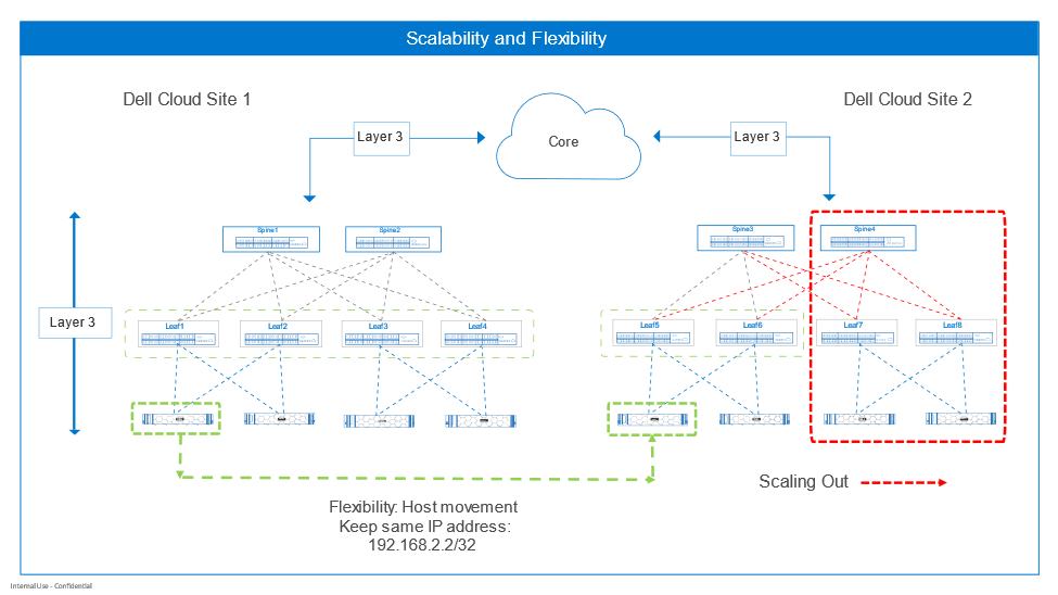
Figure 2. Scalability and flexibility
Flexibility
RoH also enhances flexibility by enabling subnet freedom for hosts across the IP fabric. Hosts can be redeployed anywhere and keep the same IP addresses. The IP fabric uses BGP to communicate new routes to the host. This can be compared with the standard of configuring Layers 2 and 3 at the leaf-host interface. Hosts are bound to the leaf switches per rack. Migration of the host while keeping the same IP address is possible but requires additional extended VLAN configuration.
Figure 2 illustrates the flexibility RoH offers with a use case. The customer must move a host from Site 1 to Site 2. The host IP address must not be changed to prevent breaking associated applications. The host operating system and applications are moved to Site 2 by the preferred method. When the host comes up, it advertises its /32 route prefix (192.168.2.2/32) to the leaf switches, and the route is propagated throughout with BGP. The switch’s routing information base (RIB) and forwarding information base (FIB) tables are updated by BGP with the route to the host.
Increased switch performance
RoH can also increase performance by reducing latency at the host-to-leaf boundary. Each Dell data center switch has a high-performance network processing unit (NPU) at its core that empowers the rich set of network capabilities available with Dell data center switches running Dell SmartFabric OS10.
The NPU has internal pipelines that handle ingress and egress packet processing for each port based on how the switch is configured by the user.
The number of features enabled at Layer 2 and Layer 3 can affect latency through the switch, as shown in Figure 4. With the traditional Layer 2 and Layer 3 hybrid connection from switch to host, the NPU must process packets at Layer 2 such as VLAN assignment, LAG, and STP operations. It also performs Layer 3 functions like maintaining IP host tables, the RIB, and the FIB.
Layer 3 BGP End-to-End is configured between the switch ports and the host. Layer 2 packet processing is not performed because only Layer 3 is used. This can decrease latency from port to port compared with configuring Layer 2 and Layer 3 on the switch port as traditionally done. The simplicity of RoH can increase performance and simplify host and network configuration tasks.
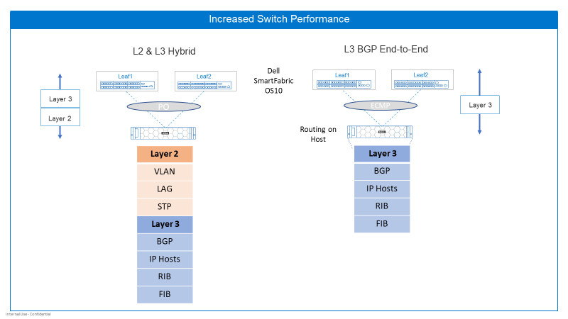
Figure 3. Increased switch performance
In summary, enabling RoH with Dell SmartFabric OS10:
- Enhances scalability in and out: Hosts can be added or removed with minimal reconfiguration.
- Enables you to move hosts around and keep the same IP address: BGP enables the network to learn the best route to the host no matter where it’s hiding.
- Simplifies the protocol stack: There is less protocol overhead and less to configure on the host and switch.
Related blogs

Automation with Ansible Collections, the next step in your network automation journey

Thu, 03 Nov 2022 14:03:56 -0000
|Read Time: 0 minutes
SmartFabric OS10 Ansible Collection
Dell SmartFabric OS10 Ansible Collection has a lot to offer for your network automation of Dell PowerSwitches. In this blog, I am going to dig a little deeper into the roles of the Ansible Collection. Ansible has continued to evolve over the years, and I can say from experience that the introduction to Ansible can be a little overwhelming at first.
The well-organized Ansible documentation helped me to understand the workings of Ansible and to quickly get started.
Ansible Galaxy near me
I want to mention that the great part of the Ansible evolution is the introduction of the Ansible Collection. Ansible Collection is a simpler method to package and distribute Ansible content. The Ansible Collection contains useful resources: readme files, module and role parameter descriptions, and Ansible playbook examples. Dell SmartFabric OS10 Collection has multiple modules, roles, and plugins that enable you to configure your Dell PowerSwitch devices with multiple playbook examples.
The Ansible framework has the common integrated roles, modules, and plugins included on your Ansible control node. The extension to that is the Dell SmartFabric OS10 Ansible Collection which includes the roles, modules, plugins specific to provision the Dell PowerSwitch. Combined they are the components that create the YAML playbooks, inventory files, group var files, and host var files used to manage your Dell SmartFabric switches. Ansible is an open-source project and the community upstream distribution method for Collections is the Ansible Galaxy website, where you can access Dell SmartFabric OS10 Collections. The repository for Ansible Galaxy Collections and the Dell SmartFabric OS10 Collection is on the GitHub website. The current Dell SmartFabric OS10 Collections namespace to search for on GitHub is dellemc.os10. The Dell SmartFabric OS10 Collection documentation provides a great overview and links to each of the roles.
Start with the Readme
I want to point out that collections and roles have their own readme. The collections readme provides a good overview of the collection. The role readme provides the details on each role, so let us dig into this Role readme. Each role readme will better explain the role variables, parameters, and key values. Each key parameter has a short description or notes on how to use the role key. The role readme includes all the important information explained in an easy-to-read table. Examples of each key type are provided, whether it is a string, list, integer, Boolean value, state value, or dictionary. I highly recommend reviewing the playbook example in the role to get a good sense of how the role and its parameters are structured.
There are typically multiple key parameters for each role. Each role may require a series of keys and values to describe the intended state the playbook will check for on the device. Typically, the series of key:value pairs are part of the host_vars file for each device accessed by the playbook. Using roles provides flexibility with your playbooks and host_vars files for your network automation.
The other valuable information provided in the role readme is the connection variables section. This section provides the information needed to communicate to your switch. You can place the connection information in your host_vars file, inventory file, or the playbook.
The example playbooks provide the most insight on how the collection interacts with your managed switch. The example playbook explains the components and workings of the role inside the playbook and interactions with the switch inventory file, switch host_vars, and switch group_vars files. The example playbook provides details down to the syntax and spacing of each key:value pair, to get you off the ground and running.
Show me the Role
The following example is an excerpt from the VLAN role, within the Dell SmartFabric OS10 Collection.
This role facilitates configuring virtual LAN (VLAN) attributes. It supports the creation and or deletion of a VLAN and its member ports. This role is abstracted for Dell PowerSwitch platforms running Dell SmartFabric OS10.
The VLAN role requires an SSH connection for connectivity to a Dell SmartFabric OS10 device. You can use any of the integrated operating system connection variables.
- Example role variables (see the VLAN role for the full list) role is abstracted using the ansible_network_os variable that can take dellemc.os10.os10 as the value.
- os10_vlan (dictionary) holds the key with the VLAN ID key and the default-VLAN key.
- The VLAN ID key should be in format "vlan ID" (1 to 4094)
- Variables and values are case-sensitive
Table 1: VLAN ID keys
Key | Type | Notes | Support |
description | string | Configures a single-line description for the VLAN | os10 |
tagged_members | list | Specifies the list of port members to be tagged to the corresponding VLAN | os10 |
Note: See the VLAN role for the full table.
Ansible Dell network roles require connection information to establish communication with the nodes in your inventory.
Table 2: Example connection variable
Key | Required | Choices | Description |
ansible_host | yes | N/A | Specifies the hostname or address for connecting to the remote device over the specified transport |
ansible_ssh_user | no | N/A | Specifies the username that authenticates the CLI login for the connection to the remote device; if value is unspecified, the ANSIBLE_REMOTE_USER environment variable value is used |
Note: See the VLAN role for the full table.
Ansible playbook
Let us wrap up this discussion with the Playbook. An example playbook with a simple host file and an inventory file are shown below.
Example playbook.yaml file:
---
- hosts: os10_switches
connection: network_cli
collections:
- dellemc.os10
roles:
- os10_vlan
Example host_vars/os10_sw1.yaml
hostname: os10_sw1
# Parameters for connection type network_cli
ansible_ssh_user: xxxx
ansible_ssh_pass: xxxx
ansible_network_os: dellemc.os10.os10
# Create vlan100 and delete vlan888
os10_vlan:
vlan 100:
description: "Edge Group1"
state: present
vlan 888:
state: absent
Example inventory.yaml file:
[os10_sw1]
os10_sw1 ansible_host=100.104.28.119
[os10_sw2]
os10_sw2 ansible_host=100.104.28.120
[os10_switches:children]
os10_sw1
os10_sw2
Run the playbook
Run the playbook using the following simple Ansible-playbook syntax:
Ansible-playbook -i inventory playbook.yaml
Conclusion
I recommend starting your automation and innovation journey now. Dell SmartFabric OS10 Collections offer a great deal of options to include in your Ansible automation journey for your Dell PowerSwitch devices and overall DevOps and NetOps Automation ecosystem. Go to the Ansible Galaxy website to review the Dell SmartFabric OS10 Collection roles and details. Another key resource is the Dell Fabric Design Center, where you can interact and build your network fabric and download the switch configurations in OS10 or Ansible playbook collection format.
Additional information
For more about Ansible Dell SmartFabric OS10 Collections by Dell Technologies, see:
- Dell Technologies Info Hub
- Network Automation Journey with Ansible
- Simplify BGP EVPN VXLAN data center deployment challenges with Ansible
- Dell Demo Center
- Dell Fabric Design Center.
Introduction to Ansible Network Collection for Dell SmartFabric Services
Wed, 19 Oct 2022 18:54:48 -0000
|Read Time: 0 minutes
SFS Ansible collection
With Dell OS10.5.4.0, the OS10 Ansible automation journey continues. Ansible helps DevOps and NetOps reduce time and effort when designing, managing, and monitoring OS10 networks in enterprise IT environments. Updates to Ansible collections provide new automation benefits for increased operational efficiencies. This blog provides a quick introduction to the Ansible network collection for Dell SmartFabric Services (SFS).
The Ansible network collection for SFS allows you to provision and manage OS10 network switches in SmartFabric Services mode. The collection includes core modules and plugins and supports network_cli and httpapi connections. Supported versions include Ansible 2.10 or later. Sample playbooks and documentation are also included to show how you can use the collection.
With this introduction, there are now additional SFS automation choices. The following table lists some examples of the included modules:
| Module Name | Module Description |
|---|---|
sfs_setup | Manage configuration of L3 Fabric setup |
sfs_backup_restore | Manage backup restore configuration |
sfs_virtual_network | Manage virtual network configuration |
sfs_preferred_master | Manage preferred master configuration |
sfs_nodes | Manage nodes configuration |
More SFS automation choices
The SmartFabric OS10 SFS feature provides network fabric automation. The SFS leaf and spine personality is integrated with systems including VxRail and PowerStore. SFS delivers autonomous fabric deployment, expansion, and life cycle management. SFS automatically configures leaf and spine fabrics. SFS for leaf and spine is supported on S-series and Z-series Dell PowerSwitches. See the Support matrix for a complete list of supported platforms. For more details see Dell SmartFabric Services User Guide, Release 10.5.4.
You can access the collection by searching for dellemc.sfs on the Ansible Galaxy website. For more information, see the Dell OS10 SmartFabric Services Ansible collection.
 Ansible for SFS now available
Resources
Ansible: Adding Security to Your Playbooks Using Ansible Vault
Mon, 19 Dec 2022 21:40:16 -0000
|Read Time: 0 minutes
Security for your Ansible Network Automation
Let me introduce Ansible Vault. Ansible Vault provides the security for your playbooks’ sensitive data. You can use Ansible Vault to encrypt any Ansible data from a single variable to a file within the Ansible projects. As we continue to explore Ansible network automation, consider including the security capabilities provided by Ansible Vault.

How does it work
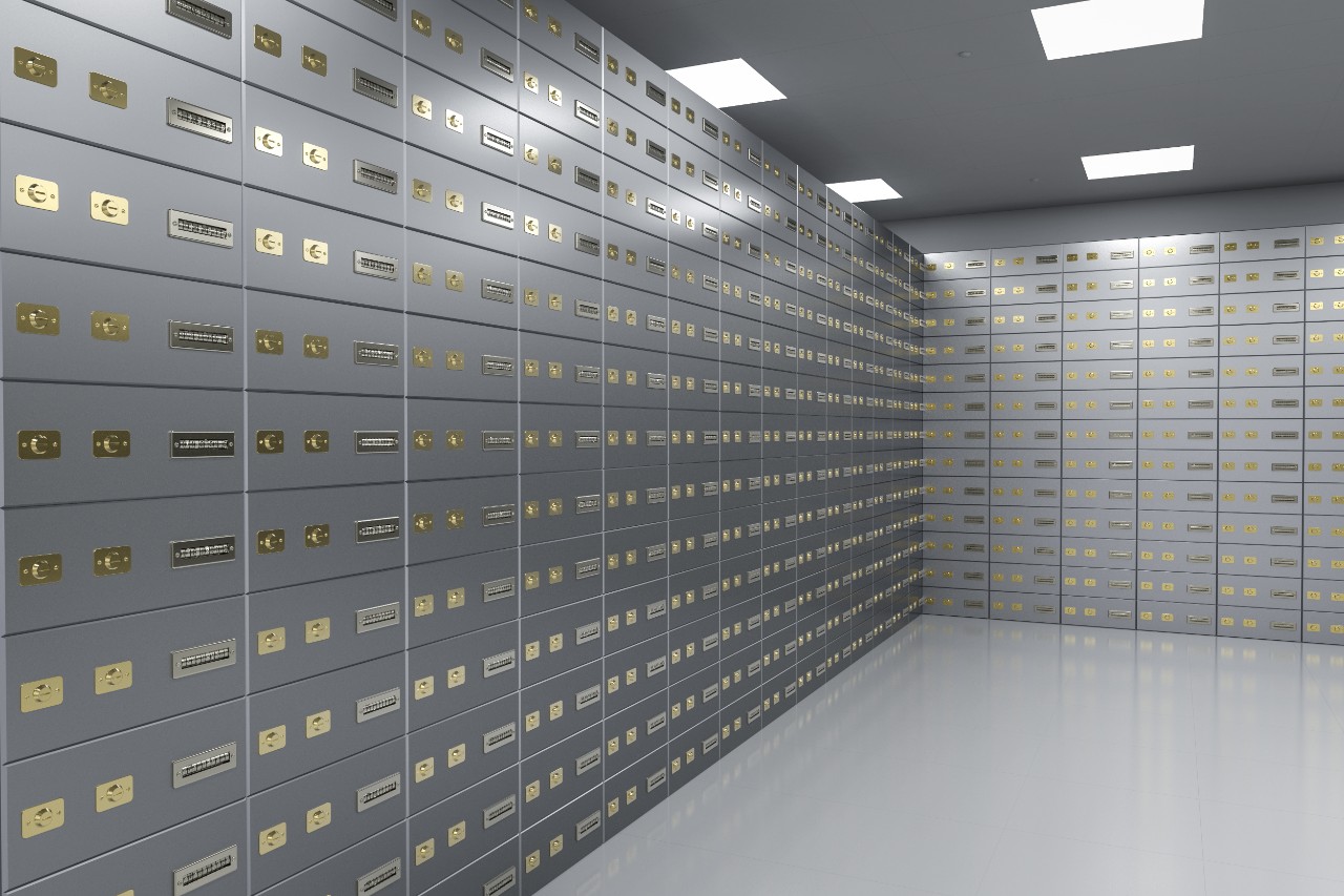
Think of a bank vault with many locked vault drawers. A vault drawer key is needed to retrieve the sensitive content. In the same way, Ansible vault creates the vault drawer while you provide the key (password).
Ansible Vault is a password-based authentication feature that is built in with the Ansible framework. Ansible Vault adds security in the form of encrypted Ansible data for the playbooks, host_vars, group_vars, or inventory files. For example, with Ansible Vault, you can encrypt sensitive Ansible data like the switch login credentials used when running playbooks.
By now you might be wondering, “Where do I start?”
Start the encryption process on the Ansible automation control node.
Easy to use and implement
The ansible-vault command-line utility is simple to use. The overall process to implement Ansible Vault is straightforward.
In one implementation option, you provide the vault secret password when you initially encrypt the Ansible data, in this case the switch login credentials. The vault password “key” is then associated with the vaulted encrypted data within Ansible Vault.
Here is the ansible-vault utility command structure to encrypt a string.
ansible-vault encrypt_string <password_source> '<string_to_encrypt>' --name '<string_name_of_variable>'
Here is an example of encrypting the string “admin” for Ansible variable “ansible_ssh_pass.”
ansible-vault encrypt_string --ask-vault-password "admin" --name "ansible_ssh_pass"
“ansible-vault” is the command-line utility.
“encrypt_string” is the vault command to encrypt a string.
“--ask-vault-password” is source providing the vault password.
“string_name_of_variable” is the Ansible variable to use the encrypted data.
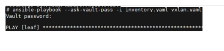
Ansible Vault requires you to provide the vault password (using a prompt or file) every time you need to run the playbook with the encrypted data.
Ansible Vault has many other commands to create, edit, view, rekey, decrypt, and more when working with encrypted data. For other implementation options, see the Ansible Vault documentation. For an interactive trial, go to Demo Center.
Additional Resources
Ansible Vault Hands-On Lab on Demo Center

Let's automate
Fri, 07 Oct 2022 20:37:54 -0000
|Read Time: 0 minutes
While there are several networking automation techniques in the industry, this blog discusses bare metal provisioning (BMP). This is a solution that optimizes deployment by automatically provisioning the hardware (networking switches) using a pre-defined configuration and Dell networking operating system images with standard protocols, such as dynamic host configuration protocol (DHCP) and common file transfer mechanisms.
BMP aims to address the typical challenges to the traditional IT model, including the following:
- Compliance
- Compatibility
- Concern across difference version of firmware and hardware for new application or development
- Security vulnerabilities
- Support for lifecycle management of networking hardware
How does BMP work?
BMP consists of three components including:
- Bare metal (hardware – BIOS with POST)
- System bootloader
- Network operating system
Bare metal is hardware, bootloader is an (ONIE) that loads and starts the boot time task of a network operating system into working memory, the network operating system is the software component that acts as an interface between the dell switch hardware components and the end user. DHCP and file transfer service to provide OS image and pre-defined configuration (installer) to the Dell switches over the network.
The process of the BMP includes:
- When an ONIE-enable network switches boots for the first time, the boot loader launches the kernel and starts the ONIE discovery and execution (ODE) application.
- The ODE uses several methods (such as local file, DHCP, IPv6 neighbors, mDNS/DNS-SD) to locate and download (via HTTP/TFTP/FTP) an OS image and pre-defined configuration once the installer is found.
- The ODE starts the installer, which provisions the switches.
The reference of network operating system to bare metal provisioning includes the following:
- Dell SmartFabric OS10
- SONIC to Enterprise SONiC Distribution by Dell Technologies
- Third party applications
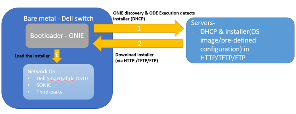
Figure 1. Components of bare metal provisioning process
With BMP, IT can adopt an open network hardware ecosystem that enables end users to choose different network operating systems without worrying about the proprietary requirement from a single vendor for scalable, cost-effective, application integration, and efficiency.
The following list provides an overview to benefit of adopting BMP:
- Reduces the time to install and configure the network device with pre- and post-configuration scripts for automation for mass deployment
- Helps eliminate configuration errors and ensure consistent configurations.
- Adopts open-source system, an open network operating system to diversify application ecosystem.
- Disaggregates software and hardware
Additional resources
Overview — Open Network Install Environment documentation (opencomputeproject.github.io)
Overview — Open Network Install Environment documentation (opencomputeproject.github.io)
SmartFabric Services: Static Onboarding
Wed, 14 Sep 2022 21:47:22 -0000
|Read Time: 0 minutes
SmartFabric Services (SFS) automates the configuration of a leaf-spine topology in your data center and provides a web-based user interface for SmartFabric configuration. If you have not built a SmartFabric, see Getting started with SmartFabric Services.
This article is intended to help you quickly onboard devices such as servers and storage arrays to your SmartFabric using the static onboarding method. This method is used if the NICs in the device being onboarded do not support LLDP. If your NICs support LLDP, see SmartFabric Services: Onboarding devices using the Import from Fabric Method.
Connect the device to the leaf switches
With SFS, two leaf switches are used in each rack. Each server or storage device in the rack should have at least one NIC port that is connected to each leaf for redundancy and performance. The NICs may be configured for LACP or a switch independent teaming method.
For the example in this article, a two-leaf SmartFabric has been deployed using a pair of Dell PowerSwitch S5248F-ON switches. A PowerEdge server is connected to port 1/1/11 on each switch, and two 25GbE NIC ports on the server are configured for LACP in the server’s operating system.
 Figure 1 PowerEdge server connected to leaf switches
Dell Technologies recommends connecting dedicated device management ports, such as the PowerEdge server iDRAC, to the OOB management network. The OOB management network uses a separate switch and is required for SFS. See Getting started with SmartFabric Services for more information about the OOB management network.
SFS default networks
SFS has two default virtual networks, numbered 4091 and 3939. Virtual network 4091 is the “Client Management Network” in SFS and is available for general use. Virtual network 3939 is the “Client Control Network” and is used for VxRail node discovery.
You can run the show virtual-network command at the leaf switch CLI to view the existing networks and port assignments.
Create additional networks
As devices are statically onboarded to the SmartFabric, their network assignments are made.
To create one or more networks before onboarding devices:
- From a workstation with access to the OOB management network, use a browser to connect to the management IP address of the SmartFabric leader switch.
- Log in as admin.
- In the SFS UI, select Network > Networks and expand General Purpose Networks.
- Click +CREATE.
- Enter a Network ID, a Network Name, and a VLAN number for the network. The VLAN number can be in the range 1 through 3999, excluding 3939. The VLAN number is also configured as the virtual network number by SFS.
 Figure 2 Creating a Layer 2 network
- Click CREATE.
When complete, a green Success message is displayed and the newly created virtual network appears in the General Purpose Networks list.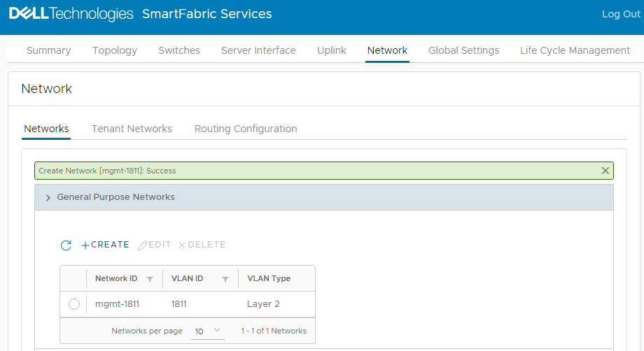 Figure 3 Virtual network 1811 created
To create additional networks as needed, repeat the steps above.
Onboard devices
If you will use OMNI vCenter integration with SFS, you will need the MAC address of each ESXi host NIC that is connected to the leaf switches. OMNI vCenter integration is a feature where ESXi hosts connected to the SmartFabric are automatically added to the correct networks as port groups are created in vCenter. See the OpenManage Network Integration User Guide Release 3.1 for more information. On PowerEdge servers, MAC addresses can be determined using the iDRAC.
If the device you are onboarding is running an operating system other than ESXi, or you will not be using OMNI vCenter integration, the MAC addresses are not required.
Ensure the device being onboarded is connected to the SmartFabric leaf switches and powered on. In this example, the server shown in Figure 1 is onboarded to the SmartFabric.
- In the SFS UI, select the Server Interface tab.
The Server Interface Profilepage displays. Figure 4 Server Interface Profile page
 - Under Server Interface Profile, click +CREATE.
The Create Server Interface Profile page displays.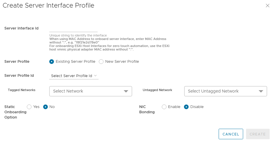 Figure 5 Create Server Interface Profile page
 - Enter a Server Interface ID.
This ID can be a string that you create such as “Server1-NIC1” or the MAC address of the connected NIC. If the MAC address is used, enter it without colons or dashes, as shown in Figure 6. The MAC address is required if you are using OMNI vCenter integration. - Select New Server Profile.
- Next to Server Profile ID, enter a profile name, such as lacp-profile.
- Next to Server Profile Bonding Type, LACP is selected for this example.
- Next to Untagged Network, select the network created earlier, 1811.
You can also select one or more networks from the Tagged Networks as needed. This is not done in this example. - Next to Static Onboarding Option, select Yes.
- Next to NIC Bonding, select Enable since LACP is used in this example.
- Select the Leaf Node and the Interface that the NIC is connected to.
- Leave Routing Protocol set to None.
The page for the first interface appears as shown: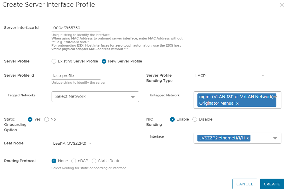 Figure 6 Server profile settings for the first interface
- Click CREATE.
The Server Interface Profilepage lists the interface.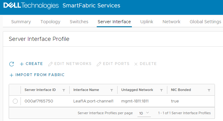 Figure 7 First interface onboarded
Because this example uses LACP, port-channel1 is automatically added to the interface name by SFS. (In SFS, port channels are automatically numbered and start with 1.) If the Server Interface Profile page still shows the interface name as ethernet1/1/port-number, allow a few seconds for the port channel to come up. Also ensure that LACP has also been configured on the server. Click the  icon to refresh as needed.
The second interface is onboarded as follows:
- Under Server Interface Profile, click +CREATE. The Create Server Interface Profile page displays.
- Enter a Server Interface ID.
- Select Existing Server Profile.
- Next to Server Profile ID, select the existing profile from the drop-down list (in this example, lacp-profile).
- Next to Untagged Network, select the network created earlier: 1811.
- Next to Static Onboarding Option, select Yes.
- Next to NIC Bonding, select Enable since LACP is used in this example.
- Select the Leaf Node and the Interface that the NIC is connected to.
- Leave Routing Protocol set to None.
The page for the second interface appears as shown:
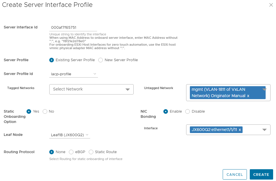 Figure 8 Server profile settings for the second interface
- Click CREATE.
When complete, the Server Interface Profile page lists both interfaces. Click the  icon to refresh the page if needed.
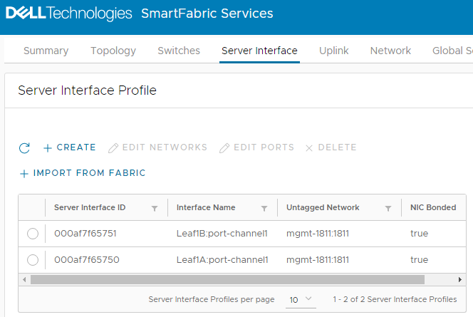 Figure 9 Interfaces onboarded
The server is now onboarded to the SmartFabric.
Resources
Dell EMC Networking SmartFabric Services Deployment with VxRail 7.0.240
SmartFabric Services: Onboarding Devices Using the Import From Fabric Method
Wed, 14 Sep 2022 21:47:22 -0000
|Read Time: 0 minutes
SmartFabric Services (SFS) automates the configuration of a leaf-spine topology in your data center and provides a web-based user interface for SmartFabric configuration. If you have not built a SmartFabric, see Getting started with SmartFabric Services.
This article is intended to help you quickly onboard devices such as servers and storage arrays to your SmartFabric using the Import from Fabric method. To use this method, the NIC connected to the leaf switches must have LLDP enabled. If your NIC does not support LLDP, you can use the static onboarding method that is covered in SmartFabric Services: Static Onboarding.
Usually, LLDP is enabled by default on NICs that support it. It is possible to disable LLDP in the server BIOS, so be sure to check your settings and documentation if SFS does not see the NIC. As an alternative, you can use the static onboarding method even if your NIC supports LLDP. However, the Import from Fabric method is easier.
Connect the device to the leaf switches
With SFS, two leaf switches are used in each rack. Each server or storage device in the rack should have at least one NIC port connected to each leaf for redundancy and performance. The NICs may be configured for LACP or a switch independent teaming method.
For the example in this article, a two-leaf SmartFabric has been deployed using a pair of Dell PowerSwitch S5248F-ON switches. A PowerEdge server is connected to port 1/1/11 on each switch, and two 25GbE NIC ports on the server are configured for LACP in the server’s operating system.
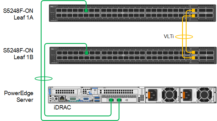 Figure 1 PowerEdge server connected to leaf switches Dell Technologies recommends connecting dedicated device management ports, such as the PowerEdge server iDRAC, to the OOB management network. The OOB management network uses a separate switch and is required for SFS. See Getting started with SmartFabric Services for more information about the OOB management network.
SFS default networks
SFS has two default virtual networks: 4091 and 3939. Leaf switch ports connected to servers with LLDP-enabled NICs are automatically untagged in virtual network 4091 by SFS. Virtual network 4091 is named “Client Management Network” in SFS. If you are using VxRail, SFS also automatically tags ports that are connected to VxRail nodes in virtual network 3939 for node discovery.
You can run the show virtual-network command at the leaf switch CLI to view the existing networks and port assignments.
Create additional networks
As devices are onboarded to the SmartFabric using the Import from Fabric method, their network assignments can be changed.
To create one or more networks before onboarding devices:
- From a workstation with access to the OOB management network, use a browser to connect to the management IP address of the SmartFabric leader switch.
- Log in as admin.
- In the SFS UI, select Network > Networks and expand General Purpose Networks.
- Click +CREATE.
- Enter a Network ID, a Network Name, and a VLAN number for the network. The VLAN number can be in the range 1 through 3999, excluding 3939. The VLAN number is also configured as the virtual network number by SFS.
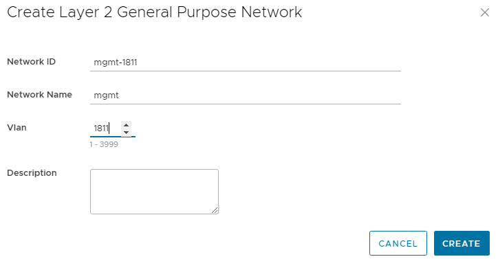 Figure 2 Creating a Layer 2 network
 - Click CREATE.
When complete, a green Success message is displayed and the newly created virtual network appears in the General Purpose Networks list. Figure 3 Virtual network 1811 created
To create additional networks as needed, repeat the steps above.
Onboard devices
Ensure the devices being onboarded are connected to the SmartFabric leaf switches and powered on. In this example, the server shown in Figure 1 is onboarded to the SmartFabric.
- In the SFS UI, select the Server Interface tab.
The Server Interface Profile page displays.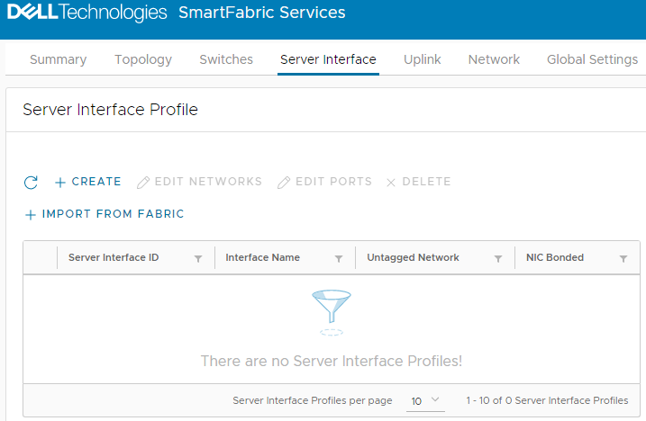 Figure 4 Server Interface Profile page
- Under Server Interface Profile, click +IMPORT FROM FABRIC.
The Discovered Server Interface page displays.
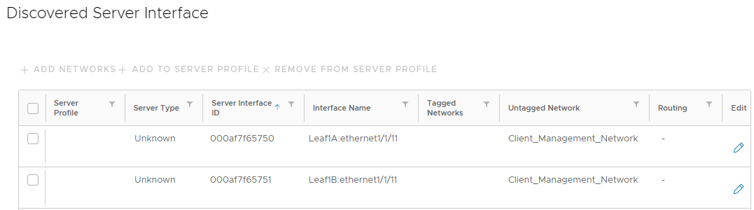 Figure 5 Discovered server interface page
Connected LLDP-enabled devices that are not yet onboarded appear in the list of discovered interfaces.
Identify the server by the ports that it is connected to (ethernet1/1/11 on both leafs in this example). The ports are shown in the Interface Name column. You can also identify the server by the MAC addresses of the connected NICs if they are known. The addresses are shown in the Server Interface ID column.
The ports are untagged in the Client_Management_Network, virtual network 4091, by default. The Server Type is Unknown. (Known server types are VxRail, PowerScale, and PowerMax devices. All other devices are classified as Unknown.)
- Check the boxes next to both server interfaces and click +ADD TO SERVER PROFILE.
- In the Server Profile dialog box:
- Select New Server Profile.
- Next to Server Profile ID, enter a profile name, such as lacp-profile.
- The Bonding Type is set to LACP for this example.
The page appears as shown: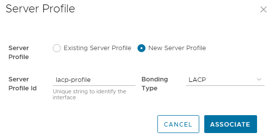 Figure 6 Server profile settings
- Click ASSOCIATE. The new server profile, named lacp-profile, is associated with the two server interfaces.
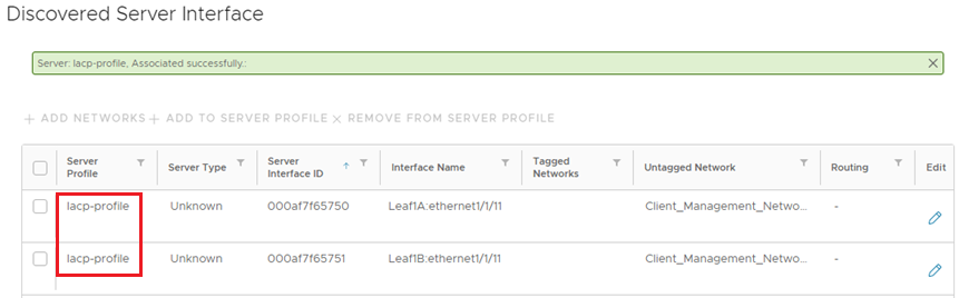 Figure 7 Interfaces added to server profile
- To change the networks that the interfaces are in, check the boxes next to both interfaces and click +ADD NETWORKS.
For this example, the untagged network is changed from the Client_Management_Network to the new network, 1811, as follows:
- In the Add Server Interface Networks window, next to Untagged Network, select network 1811. (One or more networks can also be selected from the Tagged Networks as needed. This is not done in this example.)
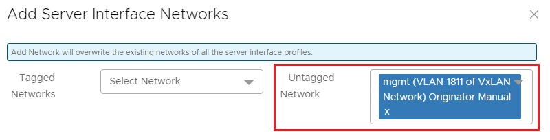 Figure 8 Network 1811 selected
- Click ADD.
The Discovered Server Interface page appears as shown. The interfaces are now untagged in network 1811.
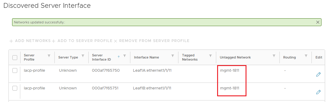 Figure 9 Untagged network changed to mgmt-1811
- Click the box next to both interfaces and click CREATE to apply the configuration.
- In the Importing Server Interface Profiles window, a success message is displayed for each interface.
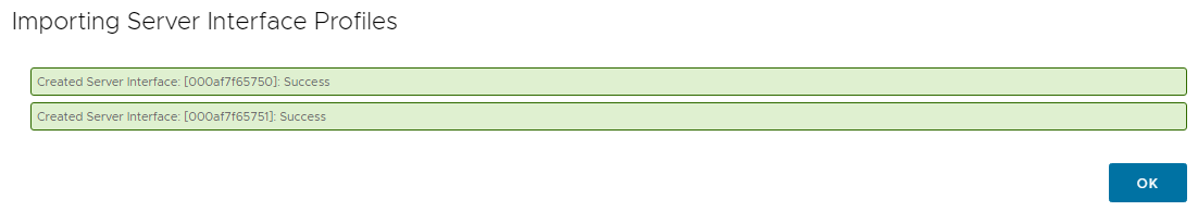 Figure 10 Success messages
- Click OK.
The onboarded interfaces appear in the Server Interface Profile list.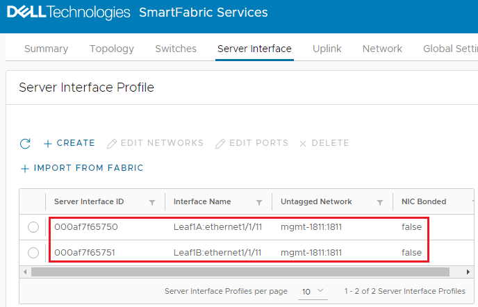 Figure 11 Interfaces onboarded
Because LACP is used in this example, NIC bonding must be enabled.
- Select the first interface and click EDIT PORTS.
- In the Edit Server Interface Profile window, set NIC Bonding to Enable. Leave the Static Onboarding Option set to No.
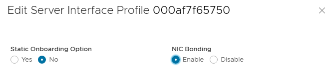 Figure 12 NIC Bonding set to Enable
 - Click EDIT to apply the change.
- Repeat steps 12 through 14 for the second interface.
When complete, the screen appears as shown. Click the icon on the Server Interface Profile page to see the changes as needed.
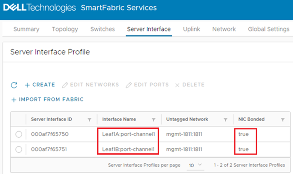 Figure 13 Interfaces configured for LACP
Because this example uses LACP, the interface name has automatically changed from ethernet1/1/11 to port-channel1. (In SFS, port channels are automatically numbered and start with 1). If it has not changed, LACP also needs to be configured on the server for the port channel to appear in the list. NIC Bonded is set to true for both interfaces.
The server is now onboarded to the SmartFabric.
Resources
Dell EMC Networking SmartFabric Services Deployment with VxRail 7.0.240
Getting Started with SmartFabric Services
Wed, 14 Sep 2022 18:47:46 -0000
|Read Time: 0 minutes
Dell SmartFabric OS10 includes SmartFabric Services (SFS) at no additional cost. SFS automatically configures a BGP EVPN leaf-spine topology in your data center and provides a web-based user interface for management of the SmartFabric.
A SmartFabric can be as small as two leaf switches in a single rack, or as large as 16 leafs in eight racks with up to four spine switches connecting the leafs between racks.
This article shows you how to quickly build a two-leaf SmartFabric.
Make the VLTi connections
With SFS, you use two leaf switches in each rack for redundancy and performance. SFS automatically configures the leafs as Virtual Link Trunking (VLT) peers. They are connected to each other with physical links that function as the VLT interconnect (VLTi). Be sure to use at least two links for the VLTi to provide fault tolerance. Both leafs in the VLT pair must be the same model. See the Dell Networking Support & Interoperability Matrix for a list of Dell PowerSwitch models that support SFS.
High-bandwidth ports available on the switches are typically used for the VLTi, because the VLTi may be used to carry data traffic in certain failure scenarios. The example shown in this article uses the two QSFP28 2x100GbE Double Density ports available on the Dell PowerSwitch S5248F-ON. These ports are numbered 1/1/49-1/1/52.
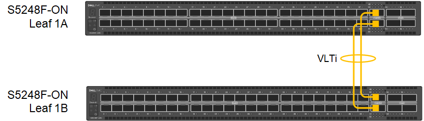 Figure 1 Leaf switch VLTi connections
 Make the OOB Connections
The out-of-band (OOB) management network is an isolated network for remote management of hardware including servers, switches, storage arrays, and other devices using their dedicated management ports. For example, PowerEdge server iDRACs are typically connected to this network.
The OOB management network is required to access the SFS web UI. It also enables switch console access using SSH and is used to carry heartbeat messages between switches that are configured as VLT peers.
At least one switch supporting 1 GbE (1000BASE-T) is required for these connections. Dell Technologies recommends using one N3248TE-ON or S3048-ON in each rack for OOB management connections. The OOB management switch is not part of the SmartFabric.
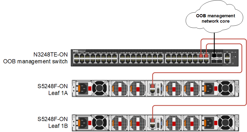 Figure 2 Leaf switch OOB management connections
Change the default passwords
For security, change the passwords of the built-in accounts, admin and linuxadmin, on each switch. The default passwords of these two accounts are admin and linuxadmin respectively. You can use the admin account to log in to the OS10 CLI, the Linux shell, and the SFS UI. You can use the linuxadmin account to log in to the Linux shell.
To change the admin password, connect to the switch console and log in as admin. Run the following commands:
OS10# configure terminal
OS10(config)# username admin password new-password role sysadmin
OS10(config)# exit
OS10# write memory
To change the linuxadmin password, connect to the switch console and log in as admin. Run the following commands:
OS10# configure terminal
OS10(config)# system-user linuxadmin password new-password
OS10(config)# exit
OS10# write memory
Repeat the above steps on the remaining switches.
For additional security best practices, see the Dell SmartFabric OS10 and SmartFabric Services Security Best Practices Guide.
Configure the OOB management IP address
If you don’t use a DHCP server on your OOB management network, configure a unique IP address on the management interface on each switch in the SmartFabric. If you use routing on the OOB management network, you can also configure a management route as shown in this example.
To configure the OOB management IP address, run the following commands on each switch:
OS10# configure terminal
OS10(config)# interface mgmt 1/1/1
OS10(conf-if-ma-1/1/1)# no ip address dhcp
OS10(conf-if-ma-1/1/1)# ip address 100.67.76.12/24
OS10(conf-if-ma-1/1/1)# no shutdown
OS10(conf-if-ma-1/1/1)# exit
OS10(config)# management route 100.67.0.0/16 100.67.76.254
OS10(config)# end
OS10# write memory
Put the switches in SmartFabric mode
Dell PowerSwitches running OS10 are in Full Switch mode by default. All leaf and spine switches in a SmartFabric must be running in SmartFabric mode. The command used to put a leaf switch in SmartFabric mode is in the following format:
smartfabric l3fabric enable role LEAF vlti ethernet VLTi_port_range
When a switch is placed in SmartFabric mode, most of the existing switch configuration is deleted. Some global settings such as the management IP address, management route, and hostname are retained. Be sure the physical VLTi connections are made before running the command.
The leaf switches in Figure 1are put in SmartFabric mode by running the following commands on each switch:
OS10# configure terminal
OS10(config)# smartfabric l3fabric enable role LEAF vlti ethernet 1/1/49-1/1/52
Reboot to change the personality? [yes/no]:y
The configuration is applied, and the switch reloads.
After reloading, you can run the following command on each switch to verify they are each in SmartFabric mode:
OS10# show switch-operating-mode
Switch-Operating-Mode : Smart Fabric Mode
Connect to the SFS UI
From a workstation with access to the OOB management network, use a browser to connect to the management IP address of either leaf switch by going to https://OOB_mgmt_ip_address. Log in as admin.
(After reloading the switches, it will take a few minutes before the UI is accessible.)
All SFS UI configuration is performed on the leader switch. If you connect to a switch in SmartFabric mode that is not the leader, a link to the leader is provided, outlined in red below.
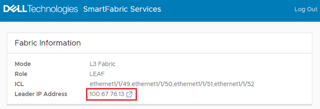 Figure 3 Connected to a switch that is not the leader
If applicable, click the link that is provided to go to the leader switch, and log in as admin.
(You can also find the IPv4 address of the leader switch by running the show smartfabric cluster command from the CLI of any switch in the SmartFabric.)
When connected to the SFS leader switch, the Summary > Overview page displays.
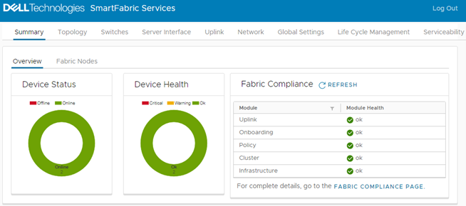 Figure 4 SFS user interface on leader switch
The Device Status box shows that there are two switches in the SmartFabric, and both are Online. The Device Health box shows that both switches are Ok.
You can perform the following tasks in the SFS UI:
- View the fabric status, health, and topology.
- Modify port settings: Set administrative state (up or down), configure MTU, enable or disable auto negotiation, configure breakout ports, and configure a jump port.
- Create server interface profiles and assign ports to networks.
- Create uplinks, including the new multisite fabric interconnect.
- Create networks and configure routing.
- Configure SmartFabric switch global settings: Configure NTP, DNS, SNMP, and Syslog servers, and modify default fabric settings such as ASNs and fabric IP addresses.
- Restore the fabric from a backup.
- Monitor fabric compliance.
The next steps are to onboard your server and storage devices to the SmartFabric, configure uplinks to your existing data center network, and deploy OpenManage Network Integration (OMNI). You can also expand your SmartFabric to additional racks by adding spines and additional leaf pairs as needed.
These tasks and others are covered in the deployment guides and user guides that are listed in the Resources section below.
Resources
SmartFabric Services: Onboarding Devices Using the Import From Fabric Method
SmartFabric Services: Static Onboarding
Dell EMC Networking SmartFabric Services Deployment with VxRail 7.0.240

Do I Need Layer 2 Switching?
Tue, 13 Sep 2022 23:21:29 -0000
|Read Time: 0 minutes
Not really, at least not anymore.
The world of computer networking is rather interesting. For the longest time, the architecture has been around a combination of Layer 2 (Spanning Tree, VLANs, Port-Channels, and so forth) and Layer 3 (IP, OSPF, BGP, and so on) features. Each of these categories comes with its own set of advantages and disadvantages.
For example, when deploying Layer 2 features such as Spanning Tree, or VLAN, scalability comes to mind. With Spanning Tree, bandwidth utilization runs at fifty percent due to links being blocked as part of loop avoidance algorithms. With VLANs, the number of IDs is limited to 4,094. Having said that, Layer 2 is simple to deploy and it is better understood.
As far as Layer 3 is concerned, IP is considered more complex than Layer 2, routing protocols such as OSPF, or BGP can be complex. Removing these inherent complexities has always been key to the overall adoption of Layer 3 deployments.
Dell SmartFabric OS10 is widely deployed across all sectors and infrastructure environments. Among these environments, large enterprise, and cloud deployments there is a unique deployment model where Layer 3 is fully extended all the way to the host. This feature is referred to as “Routing to the Host.”
Let’s eliminate Layer 2 switching
In a typical network, an end-host sends its data packet to a switch or a router so the packet can be either switched or routed to its destination. The end-host needs … but what if I told you that we can eliminate the need for a switch and connect straight.
Routing to the Host
Routing to the host is an evolution in simplicity and often deployed as a cloud-based model. It fundamentally shifts the idea in how data communication works from the end-host while bringing the benefits of a Layer 3 environment with none of Layer 2’s limitations. Routing to the host has the following characteristics:
- No VLAN needed, therefore no ID limitations and no need for a Layer 3 device to terminate these VLANs to allow inter-VLAN communication.
- Direct route advertisement allowing complete flexibility in movement by end-hosts.
- No configuration is needed. This feature is enabled by default on Dell SmartFabric OS10.
- No network loops.
- No device redundancy feature needed such as multi-chassis (MC-LAG) to provide end-host redundant connectivity.
Figure 1 shows the typical routing to a host single-site cloud-based deployment model where Layer 3 is deployed end-to-end, including the end-host.
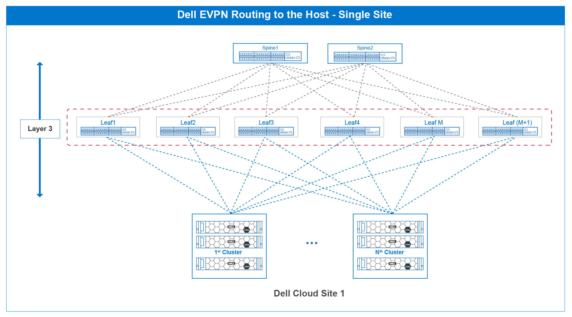
Figure 1 – Routing to the host single-site cloud reference architecture
Figure 2 shows two fabrics with routing to the host deployed on each fabric. It is here where this freedom of movement can be better understood. In typical network design where routing to the host is not deployed, the end-host needs a default gateway to send its data packet to, in this case it is the upstream leaf connection. This is often a 1:1 correlation, creating dependency.
To move a connection from the left side to the right side and vice versa, companion configurations would be needed on the leaf switches, creating unnecessary configuration churn.
With routing to the host, end-hosts are simply IP addresses moving between sites. There is no configuration tie-down to any upstream device. The routing protocols ensure these IP addresses are routed properly to their destinations.
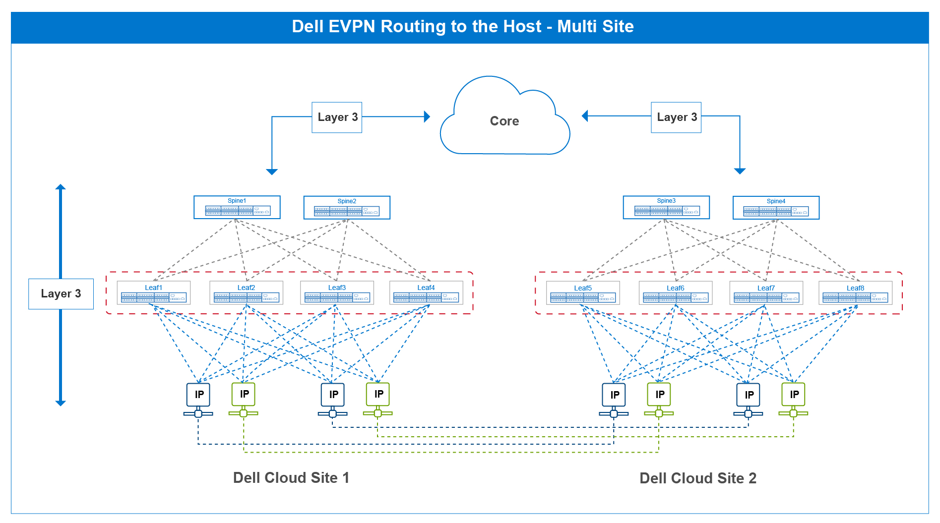
Figure 2 – Routing to the host multi-site cloud reference architecture
Routing to the host is new when compared to other Layer 3 routing features such as OSPF or BGP. However, in the short time it has been implemented, it has created a unique value proposition whenever planning any infrastructure deployment.
It is going to be interesting to see how the industry reacts and Dell Technologies is excited to see how many deployments incorporate this interesting SmartFabric OS10 feature.

Saving Time with Zero Touch Deployment
Tue, 13 Sep 2022 23:29:29 -0000
|Read Time: 0 minutes
In today’s era of connectivity, people’s online presences and the data attached are constantly expanding. While new customers are always good for business, they can be demanding on a company's IT infrastructure and the departments in charge of them. Before the release of Zero Touch Deployment (ZTD), infrastructure deployment meant dull work for the IT staff required to manually set up and configure the new equipment. However, with modern-day automation capabilities, companies no longer need to worry about spending unnecessary time and resources on these mundane tasks.
With ZTD, the process of expanding and connecting a company’s network hardware is quicker and easier than ever. IT only needs to set up the necessary configurations in a server for their switches once, and then watch as the data is automatically copied over to each additional switch that is added to the network. This process frees up valuable time for IT personnel, allowing them to direct their energy to more valuable and engaging projects.
ZTD works to provide automated switch deployment onto a network using a set of preconfigurations, allowing users a plug-and-play network environment where new devices can adjust to network settings immediately. The following figure shows a high-level overview:
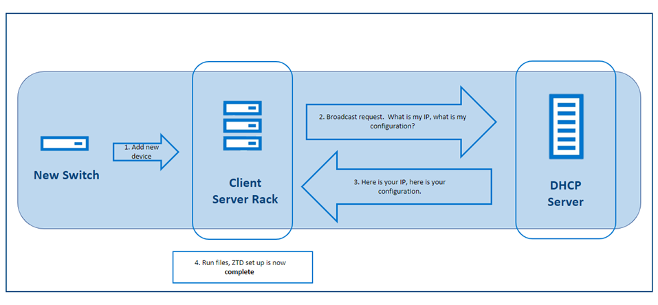
Figure 1. ZTD Automation process
By connecting the new switch to your network, it automatically downloads the configuration that it needs from the DHCP server. In addition to running the file directly from the DHCP server, you can download the file from another on-premises server or the web by using HTTP, SFTP, TFTP, or FTP. If you do not already have a preset file, there is no need to worry. The server will download and run a file with default settings, which you can modify later when you figure out your configuration.
Using ZTD instead of a manual configuration provides many benefits such as:
- Resource efficiency
- Lower costs
- Faster installation
- Improved error resolutions and quality control
- Quicker and simpler updates and changes
The first three benefits are expected with most automation projects and were described briefly in the preceding introduction. However, with ZTD, you can see the additional benefits of a central configuration file. Because all switches connect from a single source instead of independent files, it is much easier to troubleshoot where the errors occur and quickly resolve these errors for the whole network. With the convenience of a central file, you can also enjoy the ease of providing full system updates through a single source.
For more detailed information and for help setting up ZTD, see the Dell SmartFabric OS10 zero-touch deployment topic in the Dell SmartFabric OS10 User Guide at https://www.dell.com/support/manuals/en-in/networking-mx7116n/smartfabric-os-user-guide-10-5-0/dell-emc-smartfabric-os10-zero-touch-deployment?guid=guid-95ca07a2-2bcb-4ea2-84ef-ef9d11a4fa0e&lang=en-us.

Dell Technologies - A Tale of Two Fabrics
Tue, 13 Sep 2022 23:21:53 -0000
|Read Time: 0 minutes
Whenever we take public transportation or go to an airport, theater, mall, or restaurant, we feel the constant pull of our phones and other digital devices.
We feel the need to stay connected. The vast amount of information that is generated by this need has created a unique set of requirements for the telecommunication industry and its related services or application infrastructure.
The typical 3-tier networking architecture—access, distribution, and core—have evolved into a simple and scalable leaf and spine architecture. As the environment grows horizontally and application availability is needed across different data centers, there are multiple options available:
- Deploy a new leaf and spine fabric and interconnect to existing fabric.
- Add more leaf and spine switches to the existing leaf and spine environment.
This blog focuses on how the deployment of a new leaf and spine fabric can sometimes create the need for different interconnected options.
Figure 1 shows a distributed Clos architecture that is bound by EVPN BGP VXLAN. This architecture consists of an underlay and an overlay. Figure 1 also shows a single EVPN fabric in a data center. The underlay is the physical infrastructure of leaf and spine switches, while the overlay is the implementation of EVPN BGP VXLAN. VXLAN allows Layer 2 domains to be stretched across a Layer 3 cloud implemented by EVPN BGP.
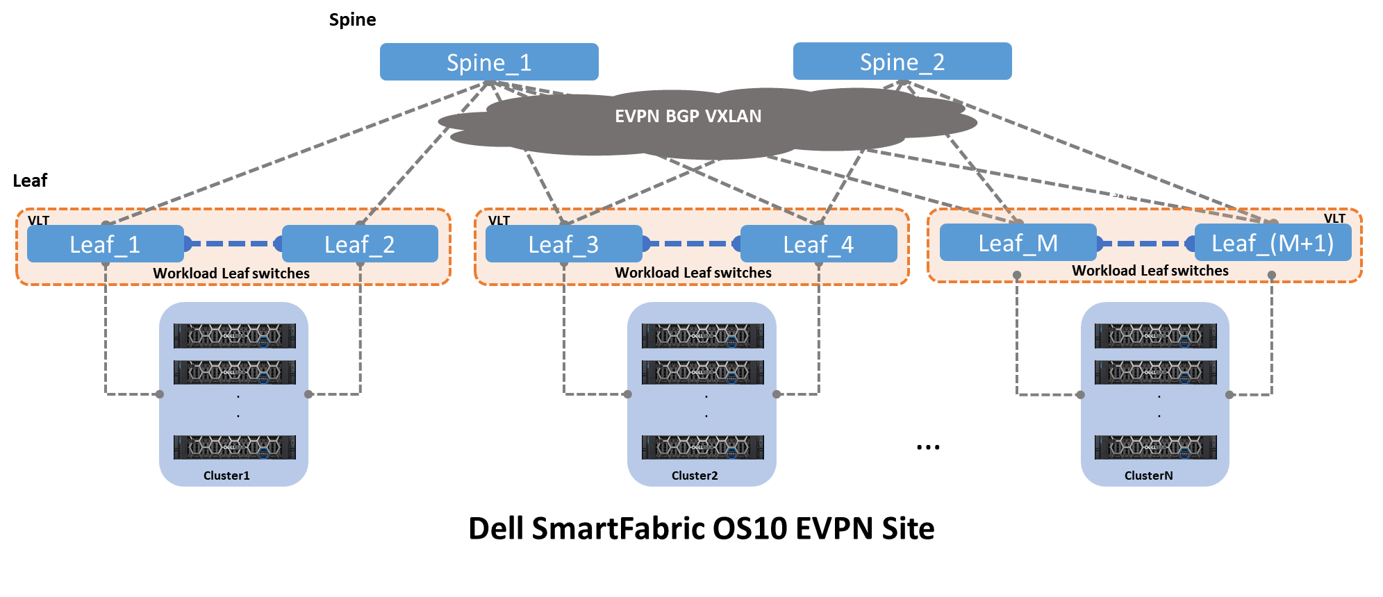
Figure 1 – Clos leaf and spine architecture with EVPN BGP VXLAN
The underlay is the physical infrastructure of leaf and spine switches, while the overlay is the implementation of EVPN BGP VXLAN.
VXLAN allows Layer 2 domains to be stretched across a Layer 3 cloud implemented by EVPN BGP.
Two key drivers create a need for a single EVPN fabric to connect to another EVPN fabric:
- Performance limitation within a single EVPN fabric
- Application availability across two or more distinct EVPN fabrics
Figure 2 shows the same architecture that is shown in Figure 1, plus the interconnect options and origins. From the spine switches, the most common type of deployment is a pure Layer 3 point-to-point. And from the leaf switches, three different deployments are seen:
- Layer 2 as trunks carrying all VLANs
- Layer 3 point-to-point
- Hybrid, that is a LAG with an IP address
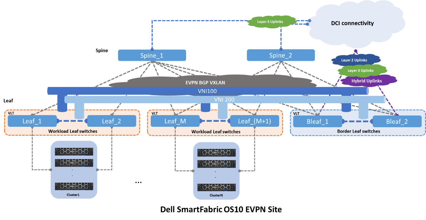
Figure 2 – EVPN BGP leaf and spine with uplinks
Fabric Interconnects
The Dell Technologies EVPN implementation provides three different interconnect options. Each of these interconnects leverages a different set of features and design guidelines.
Option 1 - Multisite EVPN with direct links
Figure 3 shows option 1, where two EVPN sites or Point of Delivery (PoDs) interconnect by direct links from the leaf switches. These links can be configured as Layer 2 or Layer 3.
If Layer 2 links are used, these links are configured as “trunks” carrying all the networks or VLANs from Site1 to Site2. This option is easy to implement and well understood, however it is prone to scalability limitations and other Layer 2
If Layer 3 links are used, these links are configured as traditional point-to-point with an IP address. The border leaf switches act as Layer 2 termination points or gateways for the networks that are defined by the workloads.
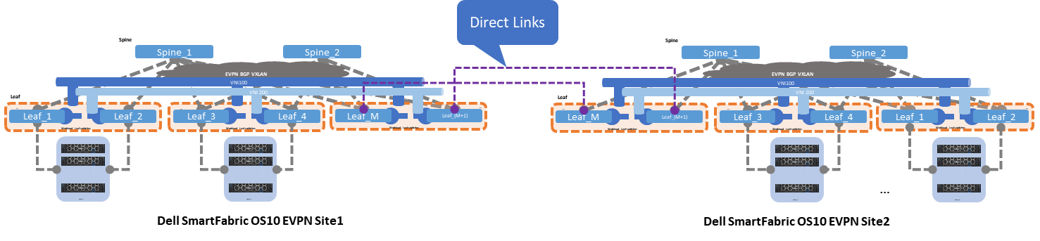
Figure 3 – Multisite EVPN with direct links
Direct links are deployed using dark fiber or some sort of patch panel, and the EVPN sites are less than 10 kilometers long. This connectivity option is often the simplest and most straightforward, but as the number of interconnects grows, this option can become difficult to manage.
The following characteristics summarize option 1:
- Interlinks (Leaf-to-Spine) speed 10/25GE
- Layer 2 interlinks
- Direct (inser-site) links speed 100GE
- Direct-link type Layer 2 or Layer 3
- Easy to implement but subject to scalability and management growing pains
Option 2 - Multisite with super spine links
The second option shows two EVPN sites that are interconnected by super spine switches. The super spine switch acts as a direct inter-site hand-off, offloading any unnecessary network traffic from the standard spine connected to the leaf switches.
Figure 4 shows the standard spine switches focusing on inter-rack traffic, whereas the super spine switches focus on inter-site traffic switching.
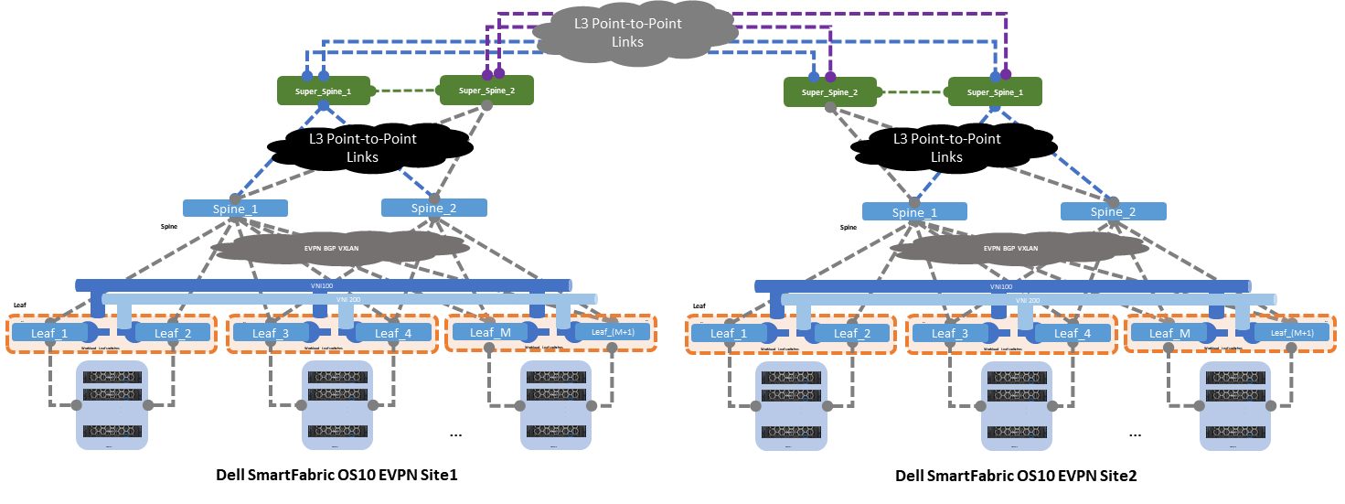
Figure 4 – Multisite EVPN with super spine link
The following characteristics summarize option 2:
- Interlinks (leaf-to-spine) speed 10/25GE
- Layer 2 interlinks (leaf to spine)
- Core links (spine-to-super spine) and (super spine-to-super spine) speed 100GE
- Layer 3 core links point-to-point
- ECMP on core links
- Moderate to implement as it requires good Layer 3 knowledge
- Better scalability
Option 3 - Multisite with indirect links
The last and third option shows two EVPN sites that are interconnected by indirect links. These links originate at the leaf switches and connect to an upstream router or switch using three different uplink deployment models:
- Layer 2
- Layer 3
- Hybrid
Layer 2 uplink
When a Layer 2 uplink is used to connect to the data center interconnect (DCI) cloud, this uplink carries only Layer 2 traffic. The uplink is configured as a “trunk” carrying multiple VLANs towards the DCI cloud. This uplink type provides link redundancy and load-balancing benefits when configured as a link aggregation (LAG).
The DCI cloud terminates all Layer 2 traffic and is configured as an EVPN BGP VXLAN overlay stretching all Layer 2 domains.
Layer 3 uplink
When a Layer 3 uplink is used to connect to the DCI cloud, the uplink is configured as a straight point-to-point Layer 3. This uplink type provides redundancy and load balancing when equal cost multipathing (ECMP) and different hashing algorithms are configured.
The DCI cloud is configured as an EVPN BGP VXLAN overlay stretching all Layer 2 domains from site to site.
Hybrid uplink
For the hybrid uplink, a LAG is configured between the border leaf switches and the upstream DCI router or switch. VRFs are used to isolate traffic type within a single tenant, and the border leaf switches point to the upstream DCI device as the default exit point.
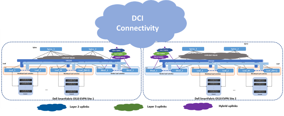
Figure 5 – Multisite EVPN with indirect links
Data will continue to increase, and the number of data centers will increase proportionally. Dell Technologies gives customers options on how to interconnect these data centers. The options that are discussed in this blog provide a basic reference, and they should be used as a starting point for any EVPN discussions.
Resources
Dell Technologies EVPN User Guide
Dell SmartFabric - Expanding the Fabric
Tue, 13 Sep 2022 23:21:53 -0000
|Read Time: 0 minutes
Three years ago, Dell Technologies introduced an innovative infrastructure orchestration approach that would establish a tight integration with the flagship VxRail mid-storage product that performs as converged infrastructure. This integration allows the deployment of a converged infrastructure to be seamless, error-free, and simple to deploy.
SmartFabric Services (SFS) came into view and made the deployment of converged infrastructure (CI), and hyper-converged infrastructure (HCI) solutions possible without the need for a deep, expert-level knowledge of networking deployment. SFS makes it possible for a Solutions Administrator to deploy an entire CI or HCI stack in minutes rather than in days or weeks.
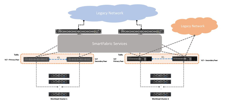
Figure 1 – SFS single-site fabric with two VxRail clusters
As SFS evolves and addresses enhancements, a key requirement remained outstanding: “How do I connect two or more SFS instances together?” Until recently, this question persisted with no set answer.
Starting with SmartFabric Services version 10.5.3.0, you can interconnect two or more SFS instances using the leaf switches by deploying Layer 3 configurations. There are two types of connections:
- Direct links – End-to-end Layer 3 direct links from spine-to-spine or leaf-to-leaf switches as shown in Figure 2.
- External links – Layer 3 links that connect to an intermediate router or switch as shown in Figure 3.
Fabric interconnect source | Fabric interconnect link type | Fabric interconnect type |
Spine | Direct Link | Layer 3 |
Spine | External Link | Layer 3 |
Leaf | Direct Link | Layer 3 |
Leaf | External Link | Layer 3 |
Table 1 – Fabric interconnects and link types
Figure 2 shows two SFS instances interconnected through direct links that are deployed from either the leaf or spine switches.
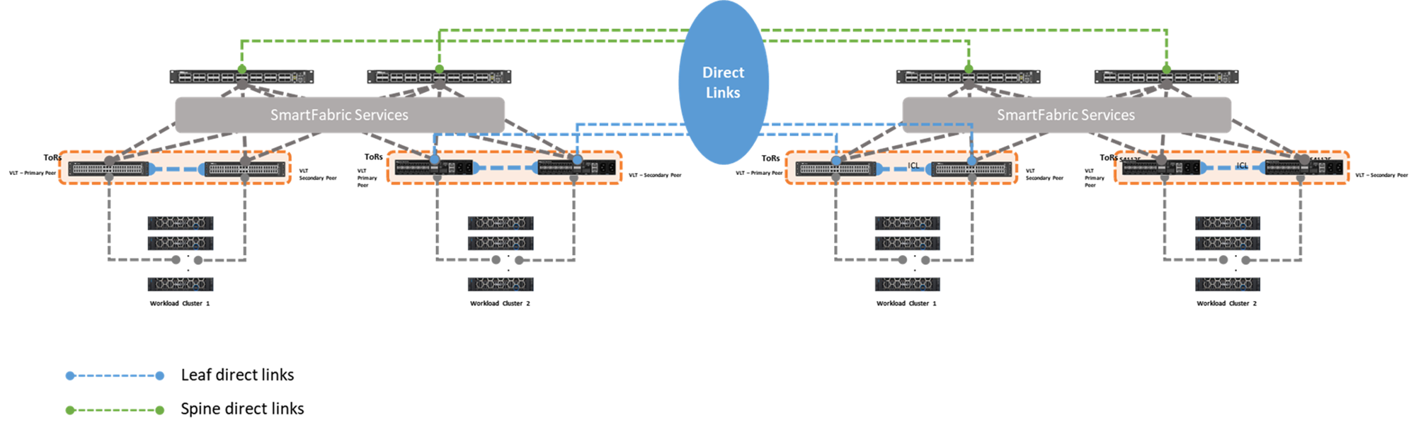
Figure 2 – Fabric Interconnect using direct links
Figure 3 shows two SFS instances interconnected through external links that are deployed from either the leaf or spine switches.
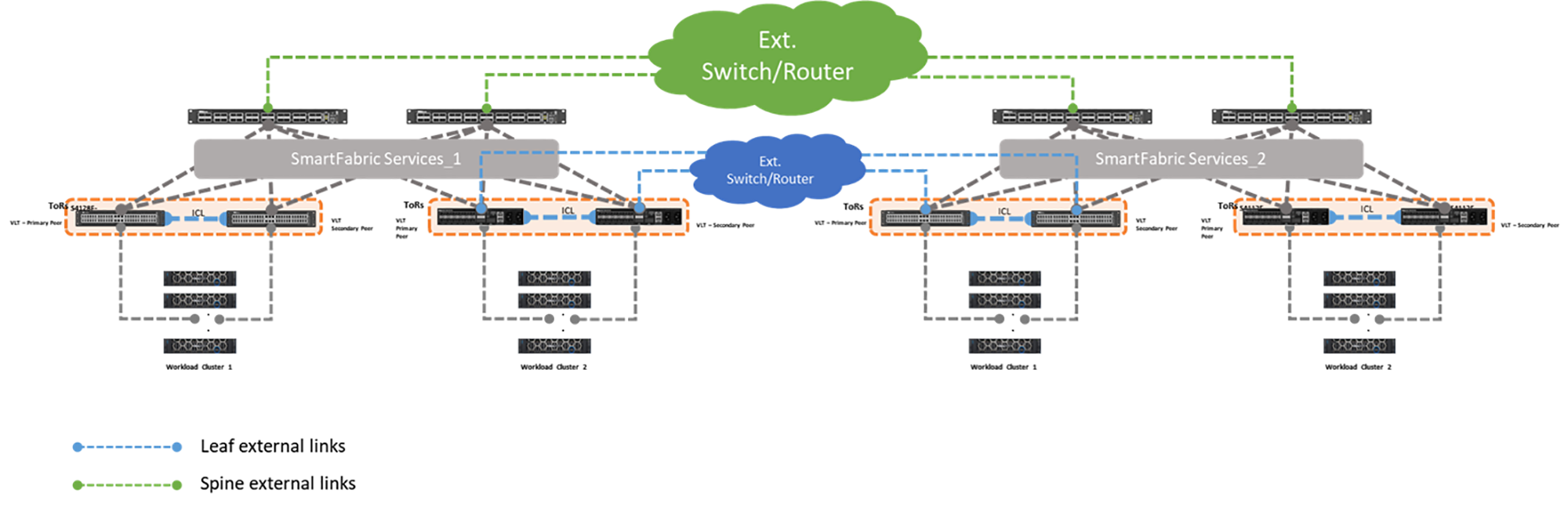
Figure 3 – Fabric interconnect using external links
Before the option to use an interconnect was available, workloads attached to an SFS instance remained isolated. This isolation did not allow for high-performing solutions such as vSAN ready nodes or PowerEdge, to scale and take full advantage of its clustering potential. By allowing different SFS instances to interconnect, a single cluster can now exist in separate physical rack locations and reduce the chances of any single point of failure.
vSAN is key in the overall converged and hyperconverged deployment. The ability to spread or stretch this service is a key differentiator for any infrastructure provider.
As part of its data center infrastructure offering, Dell Technologies now offers this capability.
For detailed deployment steps on SFS and vSAN stretch, see the SmartFabric Services and vSAN stretched Deployment Guide.

SmartFabric Services Multisite Fabric Interconnect
Wed, 23 Mar 2022 16:37:35 -0000
|Read Time: 0 minutes
OS10.5.3.2 introduces the SmartFabric Services (SFS) multisite fabric interconnect. This feature enables SFS Layer 2 virtual networks to be stretched between separate SmartFabric instances (or domains) over traditional Layer 3 networks using BGP EVPN.
Up to three separate SmartFabric domains may be connected using the fabric interconnect feature. The SmartFabric domains may be in the same data center, or in physically separate sites. One instance of OpenManage Network Integration (OMNI) can be used to manage up to 15 SmartFabric domains with a single user interface.
With the multisite fabric interconnect feature, a host connected to a SmartFabric in one site and a host connected to a SmartFabric in a different site can be in the same Layer 2 network, even when separated by Layer 3 networks. This feature allows a virtual machine to be migrated from one site to another without the need to change its IP address and gateway information. It also allows SFS to support applications such as VMware vSAN stretched clusters.
This article provides an overview of the fabric interconnect feature and its configuration steps. For a detailed step-by-step deployment example, see the SmartFabric Services with Multisite vSAN Stretched Cluster Deployment Guide.
Connection options
Separate SmartFabric domains may be connected directly to each other or through existing external switches.
Direct connection option
Figure 1 shows a direct connection between SmartFabric leaf switches in two domains.
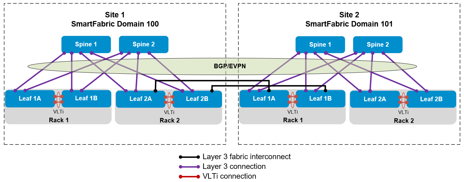
Figure 1 Direct connection between SmartFabric domains in two sites
As an option, the direct connections may be made between the spines.
External network option
Figure 2 shows two SmartFabric domains connected through an external network using the leaf switches.
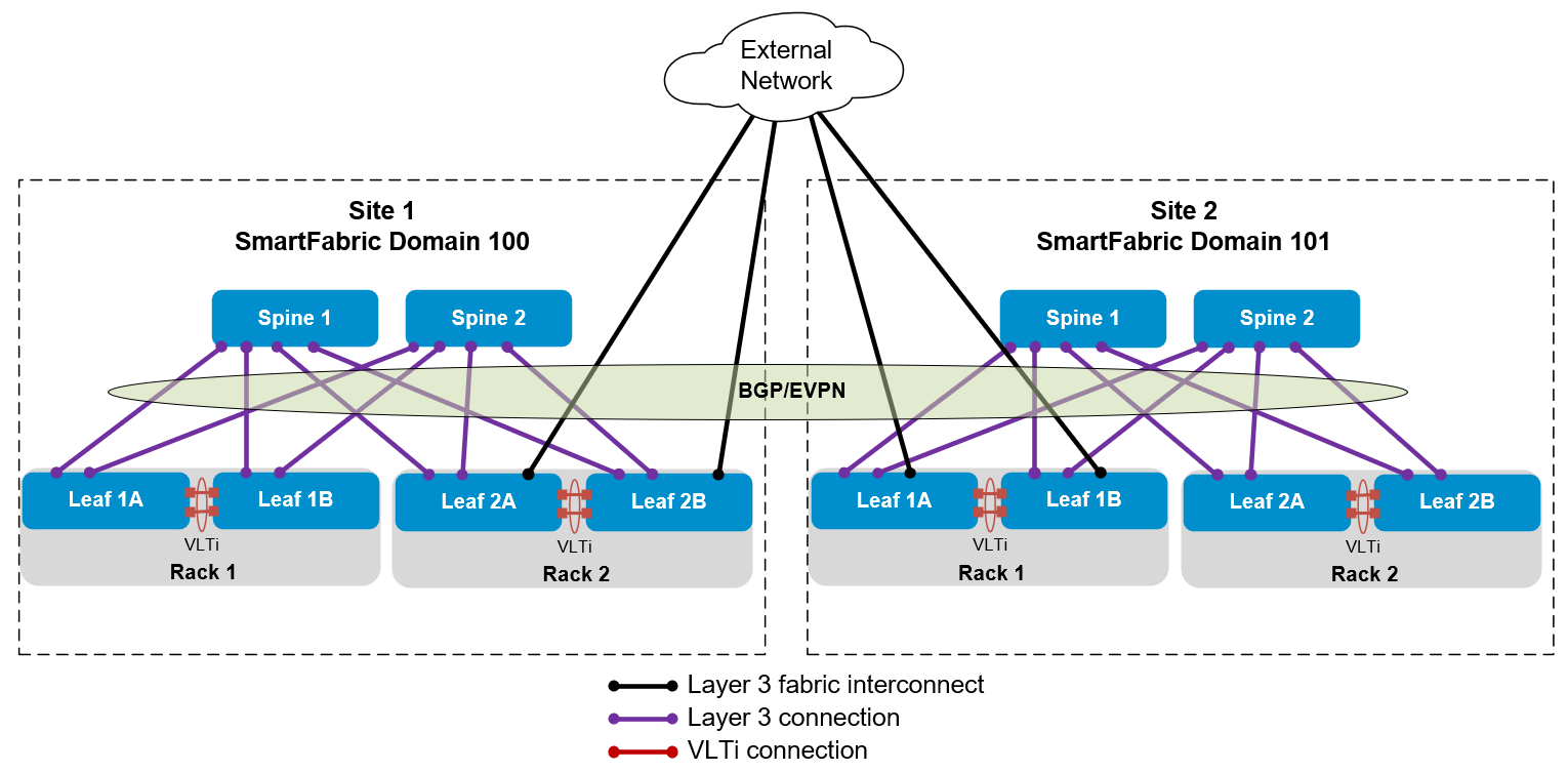
Figure 2 SmartFabric domains in two sites connected through an external network
The example covered in this article uses this topology. Optionally, the connections to the external network may be made using the spines.
SmartFabric Domain assignment
Each SmartFabric connected by a fabric interconnect to another SmartFabric must have a unique domain ID. A domain ID in the range of 100 through 107 is assigned at the time the leaf switches are placed in SmartFabric mode. (The maximum number of SmartFabric domains that may be joined using fabric interconnects is three. However, there are plans to increase this number to eight in a future OS10 release.)
If you have one SmartFabric already deployed, and did not specify a domain, its domain ID is already set to 100. The next SmartFabric created must be assigned a different domain ID if the fabric interconnect feature will be used.
The syntax to put leaf switches in SmartFabric mode is:
smartfabric l3fabric enable role LEAF vlti ethernet port_range domain domain_ID.The port_range is the range of ports used for the VLT interconnect (VLTi) between the leaf switch pair. The domain_ID is a number in the range 100 through 107. If a domain ID is not specified, it is set to 100 by default.
The syntax to put spine switches in SmartFabric mode is:
smartfabric l3fabric enable role SPINESpine switches automatically join the domain of the leaf switches they are connected to, and a domain ID is not specified in the command.
For example, the following commands are run on each leaf in the first SmartFabric domain:
OS10# configure terminal
OS10(config)# smartfabric l3fabric enable role LEAF vlti ethernet 1/1/49-1/1/52 domain 100
Reboot to change the personality? [yes/no]:y
Since Domain 100 is the default, the domain 100 portion of the SmartFabric enable command above is optional.
If Spine switches are used in the first domain, they are each placed in SmartFabric mode with the following commands:
OS10# configure terminal
smartfabric l3fabric enable role SPINE
Reboot to change the personality? [yes/no]:y
When building the second SmartFabric domain, the following commands are run on each leaf, which will be in Domain 101:
OS10# configure terminal
OS10(config)# smartfabric l3fabric enable role LEAF vlti ethernet 1/1/49-1/1/52 domain 101
Reboot to change the personality? [yes/no]:y
If Spine switches are used in the second domain, they are each placed in SmartFabric mode using the same commands as the spines in the first.
Two SmartFabric domains are now configured, one in Domain 100 and one in Domain 101. The domain ID specified determines the BGP autonomous system numbers (ASNs) and IP addresses used by default in each SmartFabric. The default SmartFabric settings for Domains 100 and 101 are shown in the following table.
| Domain ID | Leaf ASN | Spine ASN | BGP address range | VTEP address range |
|---|---|---|---|---|
100 | 65011 | 65012 | 172.16.0.0/16 | 172.30.0.0/16 |
101 | 65015 | 65016 | 172.18.0.0/16 | 172.32.0.0/16 |
You may change the ASNs and IP addresses from their defaults in the SFS UI if they conflict with the ASNs and addresses used in your existing environment.
Fabric Interconnect Configuration
Continuing with our example, SmartFabric Domain 100 is in Site 1, and SmartFabric Domain 101 is in Site 2. A pair of leaf switches in each domain connects to an external data center interconnect (DCI) switch that connects the two sites.
The external DCI switches are not part of the SmartFabric, and they have been manually configured for BGP with ASNs 65101 and 65102. The DCI switch interfaces that connect to the SmartFabric are also configured with IP addresses that will form point-to-point Layer 3 networks with the SmartFabric switches.
The SmartFabric switches are automatically configured with BGP ASNs. As shown in the previous table, leaf switches in Domain 100 use ASN 65011 by default, and leaf switches in Domain 101 use ASN 65015. Loopback addresses used as BGP router IDs are in the 172.16.0.0/16 and 172.18.0.0/16 address ranges for domains 100 and 101 respectively.
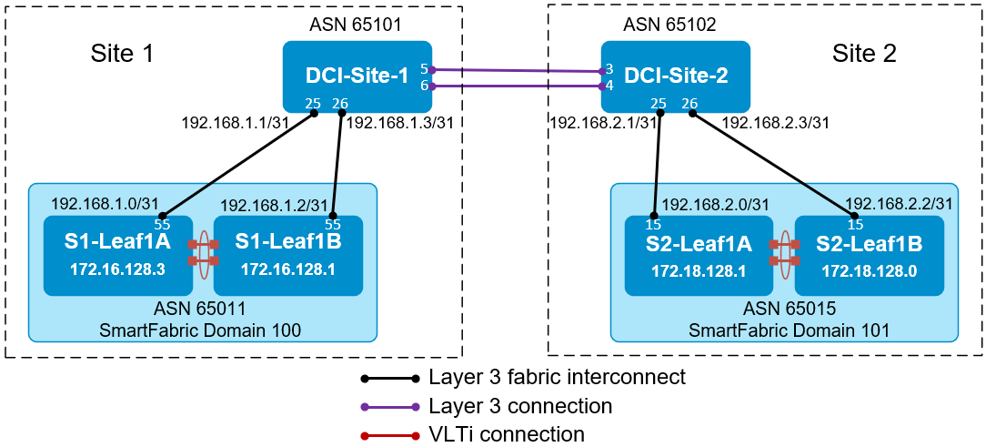
Figure 3 Fabric interconnect configuration example
The information shown in Figure 3 is used to configure the fabric interconnect in the SFS UI for each SmartFabric domain. Other leafs and spines that may be present in each SmartFabric domain are not shown. The configuration steps for this example are the same regardless of the number of switches in the two SmartFabric domains.
For Domain 100 in Site 1, the Configure MultiSite Fabric Interconnect form in the SFS UI for is filled out as shown in Figure 4.

Figure 4 Multisite Fabric Interconnect settings for Domain 100
The fields are filled out as follows:
- Switch Group - Leaf is selected since that is where the interconnect is located.
- Rack – This field is only displayed if Leaf is selected. Selecting the rack populates the lower half of form with the correct leaf pair.
- Fabric Interconnect Link – External network is selected since the connections are made through external switches.
- Peer Fabric Domain ID – 101 is the domain ID of the other fabric.
- Port – Switch service tag:Ethernet1/1/55 is the leaf port used by the fabric interconnect. It is selected from the drop-down menu.
- Local IP Address and Local Prefix Length –The IP address and prefix to be assigned to the leaf switch port are entered here.
- External ASN – 65101 is the BGP ASN configured on the external switch.
- External Interface IP – The IP address on the external switch that is on the same point-to-point network as the connected leaf switch port is entered here.
- BFD – Bi-directional Forwarding Detection (BFD) rapidly detects communication failures between two adjacent routers. As a best practice, set BFD to Enable if the external switch supports it.
- Peer BGP ASN – This field is automatically populated with the SFS default leaf ASN for Domain 101, 65015. It may be changed here if the default ASN settings for the peer domain are not used.
- Peer Loopback – The BGP loopback address for one of the two fabric interconnect leaf switches in the peer domain is entered here.
For Domain 101 in Site 2, the Configure MultiSite Fabric Interconnect page in the SFS UI is filled out in the same manner as the first domain. The completed form for Domain 101 is shown below.
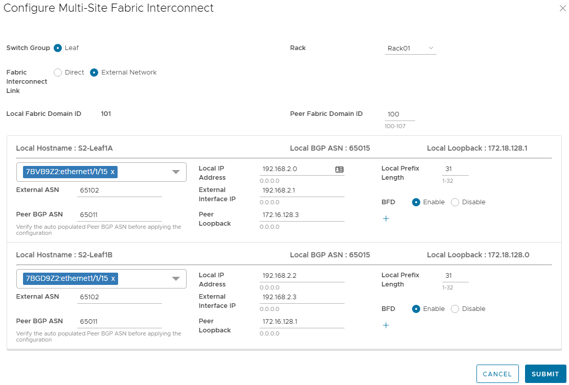
Figure 5 Multisite Fabric Interconnect settings for Domain 101
After the fabric interconnects are configured, each SmartFabric domain still has its own leader switch and SFS UI. Instead of using a separate SFS UI for each domain, use one instance of OMNI to manage up to 15 SmartFabric domains with a single user interface.
Resources
SmartFabric Services with Multisite vSAN Stretched Cluster Deployment Guide – This guide provides a step-by-step example of deploying a multisite vSAN stretched cluster in two SmartFabric domains using fabric interconnects.
Dell EMC SmartFabric Services User Guide Release 10.5.3 – The SFS user guide includes additional information about the multisite fabric interconnect feature.
OpenManage Network Integration User Guide Release 3.0 – The OMNI user guide includes information about using OMNI to manage multiple SmartFabric domains and fabric interconnect configuration with OMNI.
Dell Networking Solutions InfoHub – This site includes Dell Networking deployment guides, videos, and a support & interoperability matrix.

OMNI Bulk Configuration Spreadsheet Part 1 of 2
Thu, 02 Dec 2021 15:43:35 -0000
|Read Time: 0 minutes
Today we will cover the use of the new Bulk Configuration spreadsheet offered in OMNI 2.1. The Bulk Configuration spreadsheet will be used to create networks on the Fabric. Refer to the OMNI User Guide on the Dell EMC OpenManage Network Integration for VMware vCenter website for more details on other configuration options with the Bulk Configuration spreadsheet.
Download the SmartFabric bulk configuration template
OMNI 2.1 adds the SmartFabric bulk configuration feature. This feature allows the entry of networks, IP addresses, server interface profiles, and eBGP information into a template in Microsoft Excel (.xls) format that is downloaded from OMNI. After entering the information, the template is uploaded into OMNI and all values are applied in one step. This significantly reduces the number of configuration steps required and saves time.
NOTE: The use of the bulk configuration template is optional. The same information can be entered manually using the OMNI UI as shown in the OpenManage Network Integration for SmartFabric Services User Guide, Release 2.1. The guide is available on the Dell EMC OpenManage Network Integration for VMware vCenter website.
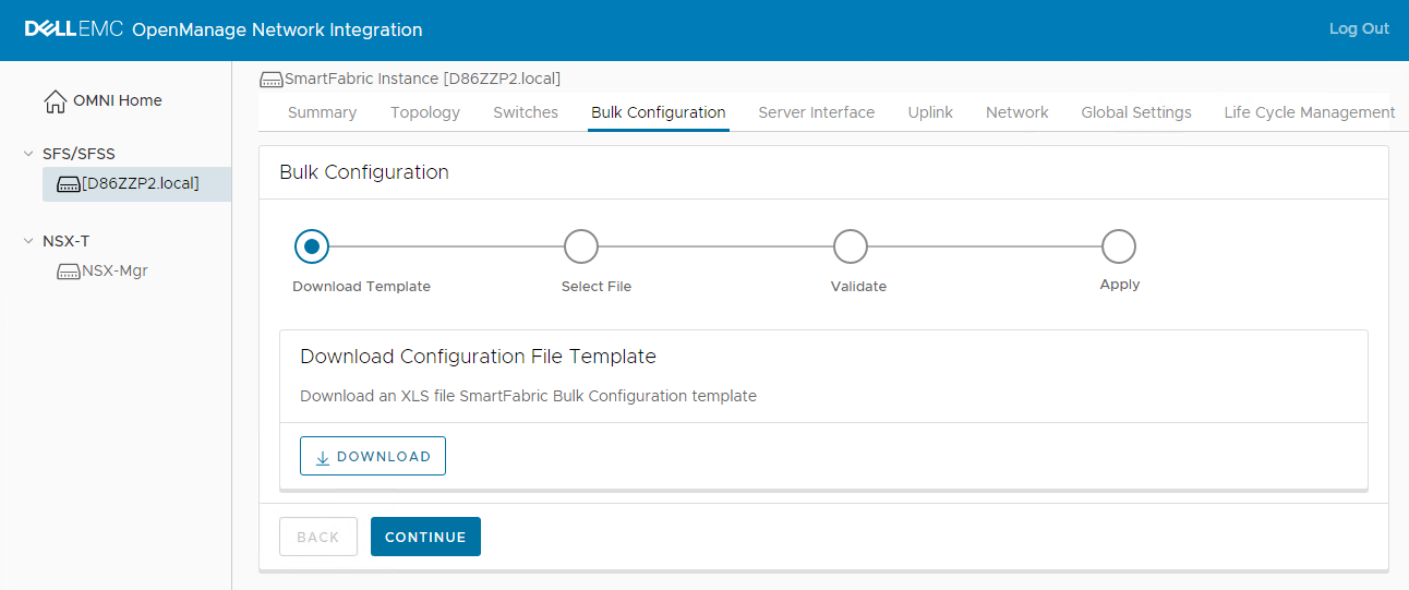
To download the template, perform the following steps:
- In the OMNI UI, select the SmartFabric instance in the left navigation panel.
- In the right navigation panel, select Bulk Configuration and click DOWNLOAD to download the template.
Configure networks
The first section will cover the addition of two different network types.
- General Purpose Network – Layer 2 (L2) or Layer 3 (L3) network that spans all racks in the Fabric.
- Multi-Rack L3 VLAN – L3 network that spans several racks, with a unique IP subnet per rack.
The General Purpose Network is the preferred network type in SmartFabric services. It can be configured as an L2 or L3 network. However, in some situations the Multi-Rack L3 VLAN is a better option. Refer to the Dell EMC Networking SmartFabric Services Deployment for VMware NSX-T deployment guide for more information on the specific use case for the Multi-Rack L3 VLAN.
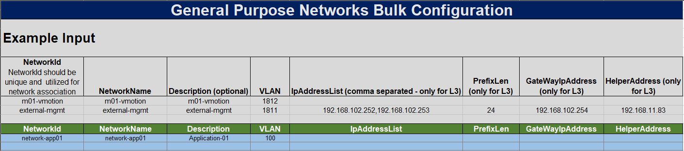
The General Purpose network used for this example has the values shown in the table below.
| Network Type | L2/L3 | NetworkID | Network Name | Description | VLAN |
|---|---|---|---|---|---|
General Purpose | L2 | network-app01 | network-app01 | Application-01 | 100 |
- Enter the specific network information into the Bulk Configuration spreadsheet on the General Purpose Network tab.
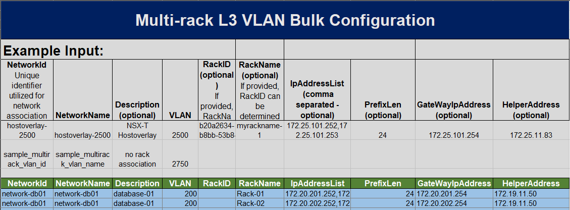
- Enter the information for our next network, which will be a Multi-Rack L3 VLAN. The values used for this example are listed in the table below.
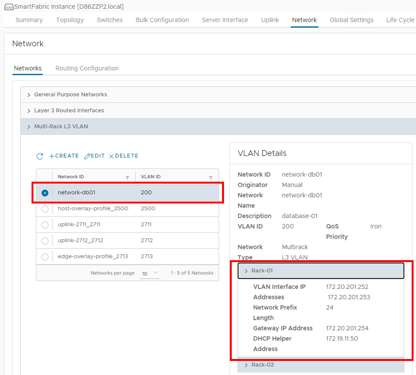
Network Type NetworkID Network Name Description VLAN Rack-Name IP Address List Prefix Gateway IP Address IP Helper Address MultiRack-L3 VLAN network-db01 network-db01 Database-01 200 Rack-01 172.20.201.252,
172.20.201.25324 172.20.201.254 172.19.11.50 network-db01 network-db01 Database-01 200 Rack-02 172.20.201.252,
172.20.201.25324 172.20.201.254 172.19.11.50
- Enter the specific network information into the Bulk Configuration spreadsheet on the Multi-Rack L3 VLAN tab.
- Once all of the information has been put into the Bulk Configuration spreadsheet, save the spreadsheet.
- Navigate back to the OMNI User Interface and upload the saved spreadsheet.
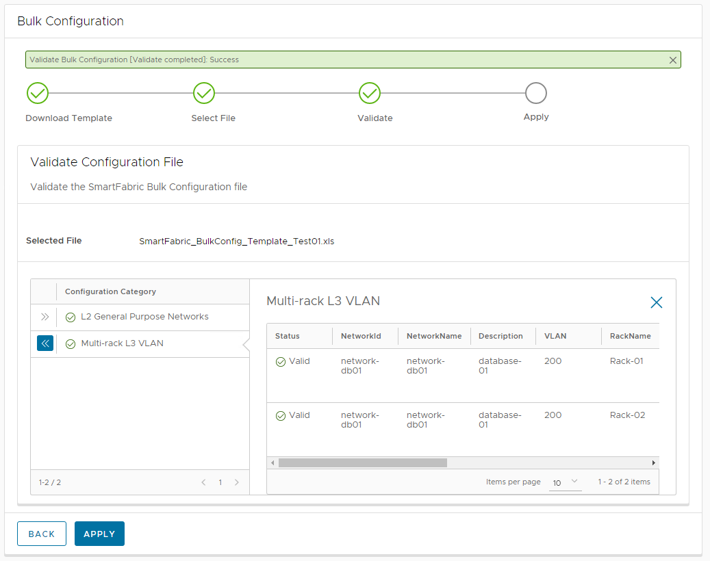
- Click Validate to validate the spreadsheet prior to Fabric configuration.
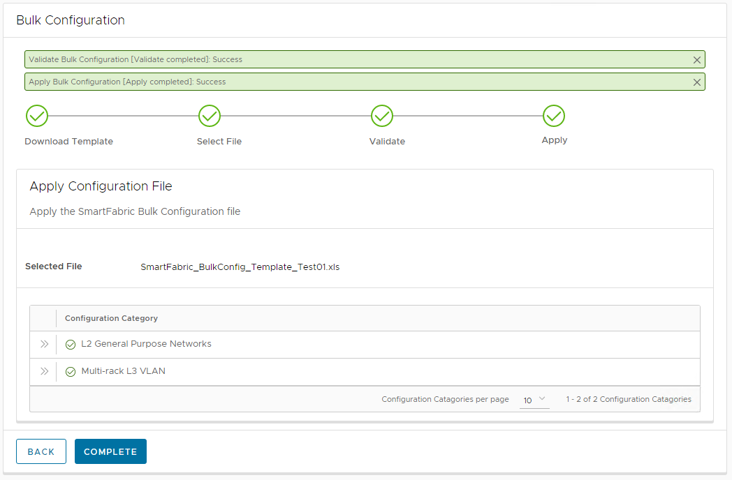
- Click Apply.
- Click Complete.
Validation of network creation
The network creation can be validated in two ways, through the OMNI UI or through the switch CLI.
Validate networks in the OMNI UI
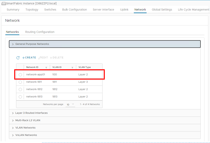
- To validate the networks through the OMNI UI, navigate to the OMNI Network tab.
- Expand the General Purpose Networks or Multi-Rack L3 VLAN tab.
The Application01 network that was specified in the Bulk Configuration spreadsheet can be seen below in the General Purpose Networks section of the OMNI UI.
The Database01 network that was specified in the Bulk Configuration spreadsheet can also be seen below in the Multi-Rack L3 VLAN section of the OMNI UI.
Validate networks in the switch CLI
Optionally, the networks may be validated using the switch CLI.
Navigate to the CLI of switches in the Fabric.
To verify the General Purpose networks, run the show smartfabric networks and show virtual-network vlan command. The output below is for one leaf in the Fabric. The output will be similar on the other leaf switches in the Fabric. The network items that were created using the Bulk Configuration spreadsheet can be seen below highlighted in yellow.
S5248F-Leaf1A# show smartfabric networks Name Type QosPriority NetworkId Vlan ------------------------------------------------------------------------------------------------------------------------------- network-app01 VXLAN IRON network-app01 100 vSAN Network 1813 VXLAN IRON network-1813 1813 uplink-2711_2711 MULTIRACK_L3_VLAN IRON uplink-2711_2711 2711 Client_Management_Network VXLAN IRON Client_Management_Network 4091 network-db01 MULTIRACK_L3_VLAN IRON network-db01 200 -----------------------Output Truncated---------------------------S5248F-Leaf1A# show virtual-network vlan Vlan Virtual Network Interface ------------------------------------------------- 100 100 port-channel1000 1811 1811 port-channel1000, ethernet1/1/1, ethernet1/1/2, ethernet1/1/3 1812 1812 port-channel1000, ethernet1/1/1, ethernet1/1/2, ethernet1/1/3 1813 1813 port-channel1000, ethernet1/1/1, ethernet1/1/2, ethernet1/1/3 3939 3939 port-channel1000, ethernet1/1/1, ethernet1/1/2, ethernet1/1/3 4091 4091 port-channel1000 S5248F-Leaf1A#
To verify the Multi-Rack L3 VLAN networks, run the show smartfabric networks and show vlan command. The output below is for one leaf in the Fabric. The output will be similar on the other leaf switches in the Fabric.
S5248F-Leaf1A# show smartfabric networks
Name                          Type                   QosPriority         NetworkId                               Vlan
--------------------------------------------------------------------
network-app01                 VXLAN                  IRON                network-app01                           100
vSAN Network 1813             VXLAN                  IRON                network-1813                            1813
uplink-2711_2711              MULTIRACK_L3_VLAN      IRON                uplink-2711_2711                        2711
Client_Management_Network     VXLAN                  IRON                Client_Management_Network               4091
network-db01                  MULTIRACK_L3_VLAN      IRON                network-db01                            200
-----------------------Output Truncated---------------------------
Note: The output of the show vlan command will not reflect the Multi-Rack L3 VLAN, if the networks are not applied to an interface through the server interface profiles in OMNI.
S5248F-Leaf1B# show vlan
Codes: * - Default VLAN, M - Management VLAN, R - Remote Port Mirroring VLANs,
       @ - Attached to Virtual Network, P - Primary, C - Community, I - Isolated
Q: A - Access (Untagged), T - Tagged
    NUM    Status     Description             Q Ports
    200    Active     database-01             T Eth1/1/2
    2500   Active                             T Eth1/1/1-1/1/3
                                              T Po1000
    2712   Active     vlan2712                T Eth1/1/1-1/1/3
    2713   Active                             T Eth1/1/1-1/1/3
                                              T Po1000
    4000   Active     vlan4000                T Po96-97,1000
    4001   Active     vlan4001                A Po96
    4002   Active     vlan4002                A Po97
*   4089   Active     vlan4089                A Po1000
    4090   Active     vlan4090                T Po1000
    4094   Active                             T Po1000
S5248F-Leaf1B#

OMNI Bulk Configuration Spreadsheet Part 2 of 2
Wed, 01 Dec 2021 19:07:54 -0000
|Read Time: 0 minutes
In part 2 of the Bulk Configuration blog, we will cover the creation of several server interface profiles using the Bulk Configuration spreadsheet.
Note: See the OMNI User Guide on the Dell EMC OpenManage Network Integration for VMware vCenter website for more details on other configuration options with the Bulk Configuration spreadsheet.
Gather server information
In this section, we will gather the MAC addresses associated with the vmnics of the ESXi hosts. OMNI requires the MAC address of the vmnics to facilitate automation for additional network creation. Once the initial server profiles are created, you can update or modify the interfaces using the server interface profiles, or through the configuration of the vDS in vCenter. OMNI monitors the vDS port group information and applies any changes made to port-groups on the physical network using the MAC addresses associated with the vmnics of the ESXi hosts.
There are two methods that can be used to gather the vmnic MAC addresses:
- Use the show lldp neighbors command on the switch CLI
- Use the ESXi Direct Console User Interface (DCUI)
Show LLDP neighbors
This section covers the use of the switch CLI to get the required MAC addresses.
- From the CLI of the SFS switch, enter the show lldp neighbors command to get the MAC address for the correct server.
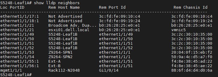
- Run the same command on each leaf switch to gather all MAC addresses associated with the required ESXi servers.
In this example, there is one connection to each leaf switch for the single ESXi host, esxi01. It is connected to ethernet 1/1/21 in the figure above.ESXi01 - NIC1
Leaf1A
b0262825e0e1
- NIC2
Leaf1B
b0262825e0e0
ESXi DCUI
Alternately, you can use the DCUI to get the details on the network adapters.
- Go to the specific server DCUI.
- Select the Configure Management Network option.
- Select Network Adapters.
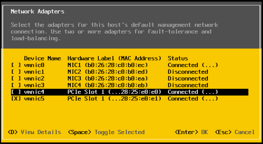
Note: If the full MAC is not visible, enter D to view the full details.
ESXi01 - NIC1 | b0262825e0e1 |
- NIC2 | b0262825e0e0 |
Create server interface profiles
Now that all the MAC addresses have been gathered, enter the information into the Bulk Configuration spreadsheet. In this example, we are applying the previously created networks to a single ESXi server. For details, refer to Bulk Config Spreadsheet Part 1.
- Open the Bulk Configuration spreadsheet.
- Go to the ServerInterface tab.
- Enter the MAC address as the InterfaceId.
- Set the NICBonded type. This example uses False.
- Set a server profile name, ESXi.
- Set the Bonding Technology, AutoDetect.
- Set the Network Tagging. This example will set both networks 100 and 200 as tagged.
Note: The server interface profile uses the NetworkID field to set the tagging. Refer to the appropriate network tab in the spreadsheet or go to the OMNI UI to get the correct NetworkID. If there are existing networks associated with these interfaces, they must be included in the spreadsheet, as the spreadsheet will override the existing configuration on those interfaces.
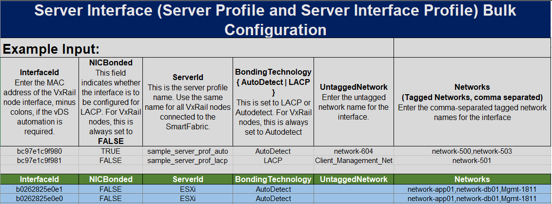
- Save the spreadsheet. You can now upload the spreadsheet to create the server interface profiles and set the correct network tagging on the switch interfaces.
- From the OMNI UI, click the Bulk Configuration tab.
- Upload the spreadsheet and select Validate.
- Click Apply.
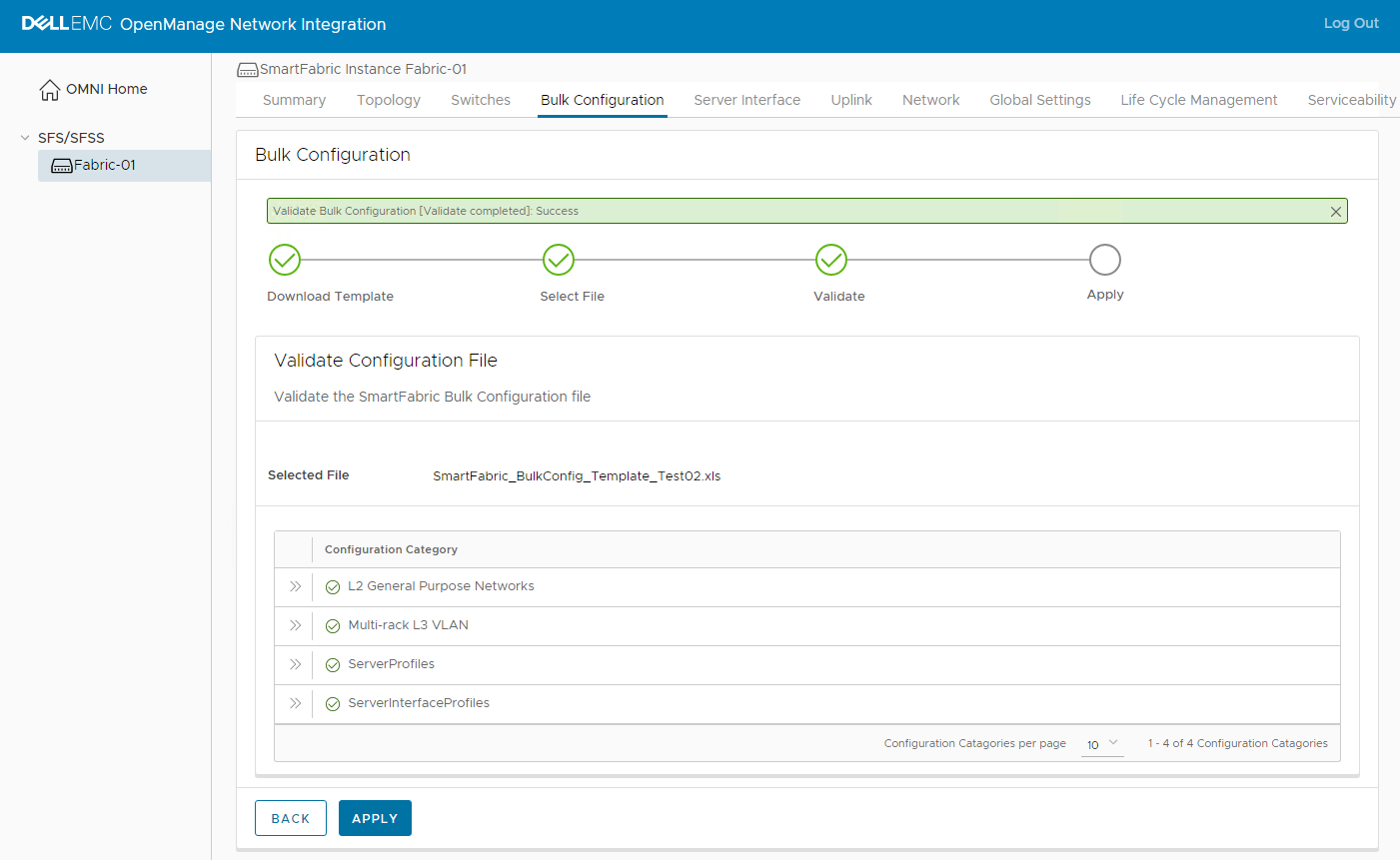
Note: If the networks from the Bulk Config Spreadsheet Part 1 blog are still in the spreadsheet, OMNI will revalidate those sections of the spreadsheet.
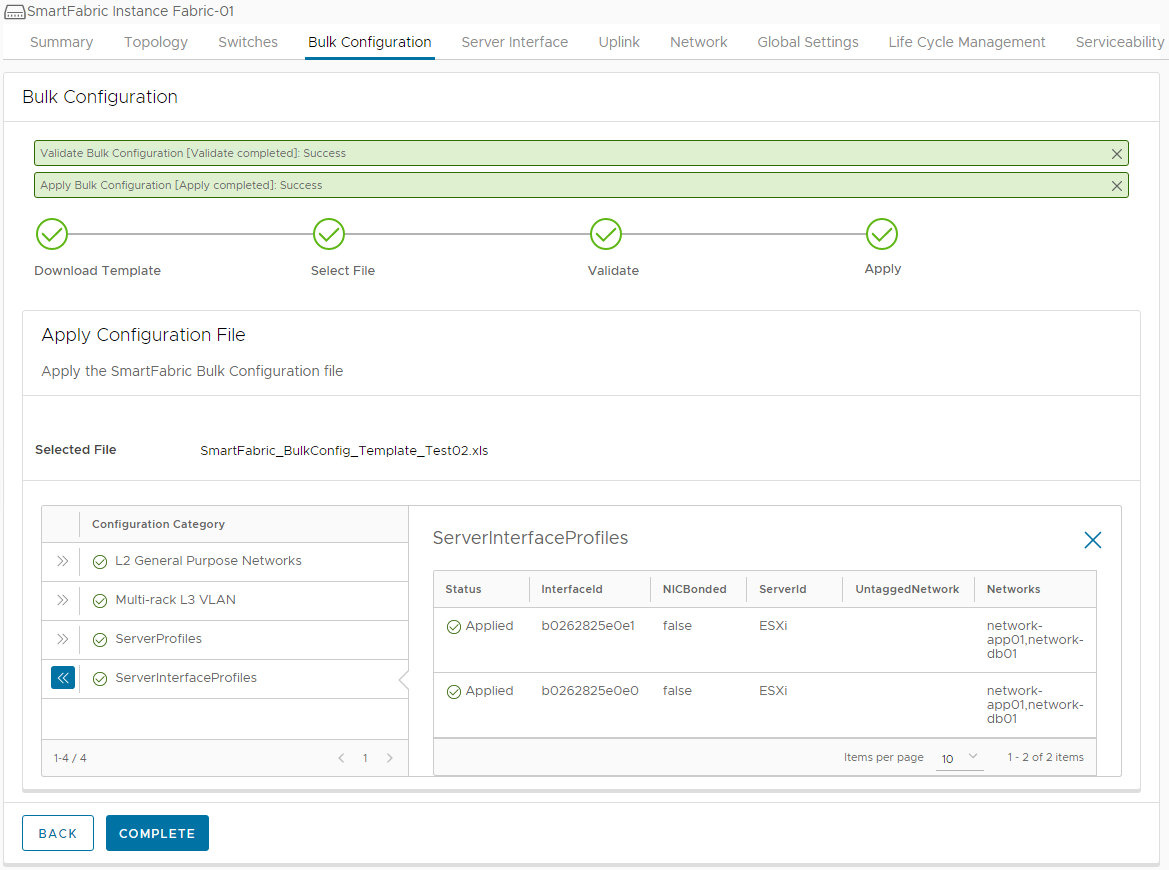
Validate the configuration
The final step will be to validate the configuration on the Fabric. This can be done in one of two ways:
- Use the Server Interface tab in the OMNI UI.
- Use the MAC addresses to locate the correct server profiles. When the specific MAC address is selected, the associated networking configurations can be seen.
The changes made in this example are highlighted with the red boxes.
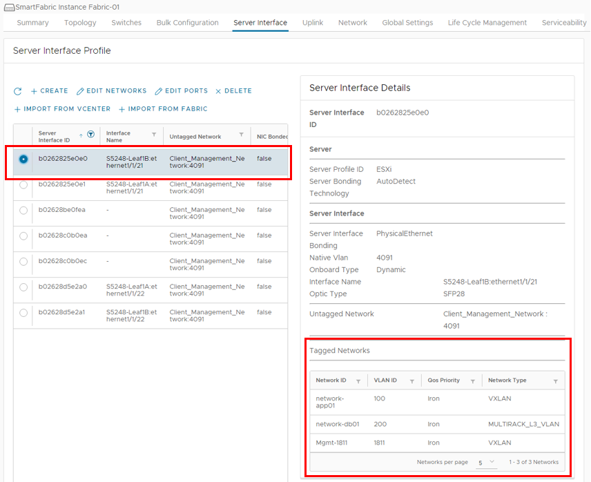
- Use the switch CLI.
- Use the show virtual network vlan command to verify General Purpose networks.
The network changes specified in the Bulk Configuration spreadsheet can be seen below, highlighted in yellow.
S5248-Leaf1A# show virtual-network vlan
Vlan                 Virtual Network     Interface
-------------------------------------------------
100                  100                 port-channel1000, ethernet1/1/21
1811                 1811                port-channel1, port-channel1000, ethernet1/1/21, ethernet1/1/22
3939                 3939                port-channel1000
4091                 4091                port-channel1000
-----------Output Truncated----------------------- Use the show vlan command to verify VLAN networks.
S5248-Leaf1A# show vlan
Codes: * - Default VLAN, M - Management VLAN, R - Remote Port Mirroring VLANs,
       @ - Attached to Virtual Network, P - Primary, C - Community, I - Isolated
Q: A - Access (Untagged), T - Tagged
    NUM    Status     Description                     Q Ports
    200    Active     database-01                     T Eth1/1/21
                                                      T Po1000
    4000   Active     vlan4000                        T Po97-98,1000
    4002   Active     vlan4002                        A Po97
    4003   Active     vlan4003                        A Po98
*   4089   Active     vlan4089                        A Po1000
    4090   Active     vlan4090                        T Po1000
    4094   Active                                     T Po1000
Simplify BGP EVPN VXLAN Data Center Deployment Challenges with Ansible
Tue, 13 Sep 2022 23:29:50 -0000
|Read Time: 0 minutes
Want to simplify BGP EVPN VXLAN deployment challenges in a data center? Automate with Ansible
Network automation offers speed and agility for deploying changes, and for retrieving data from network devices. In the world of open-source software, Ansible is a configuration management, deployment, and orchestration tool. Dell EMC Networking solutions allow the use of Ansible to provision and manage Dell EMC Networking PowerSwitch switches.
One of the solutions Ansible is engineered to deliver is EVPN VXLAN, which allows engineers to provision and manage a modern data center switch network with a VXLAN overlay with BGP EVPN. For this solution to work, you need a control host to perform all of the automation tasks. All of the switches that need to be automated should be defined in what is known as an Inventory file. Your control host will then perform all automation tasks that are defined in the playbook. A playbook is simply a set of automation tasks and instructions that are performed on a given number of hosts.
Note: For more information about Ansible, see the Network Automation Journey with Ansible blog.
The example topology in our PoC uses a leaf-spine architecture. A leaf-spine architecture allows horizontal growth, or scale-out, by adding leaf switches and bandwidth growth through the aggregate of spine switches. With the virtual machine (VM) residing across multiple nodes, leaf-spine architecture makes smooth communication possible.
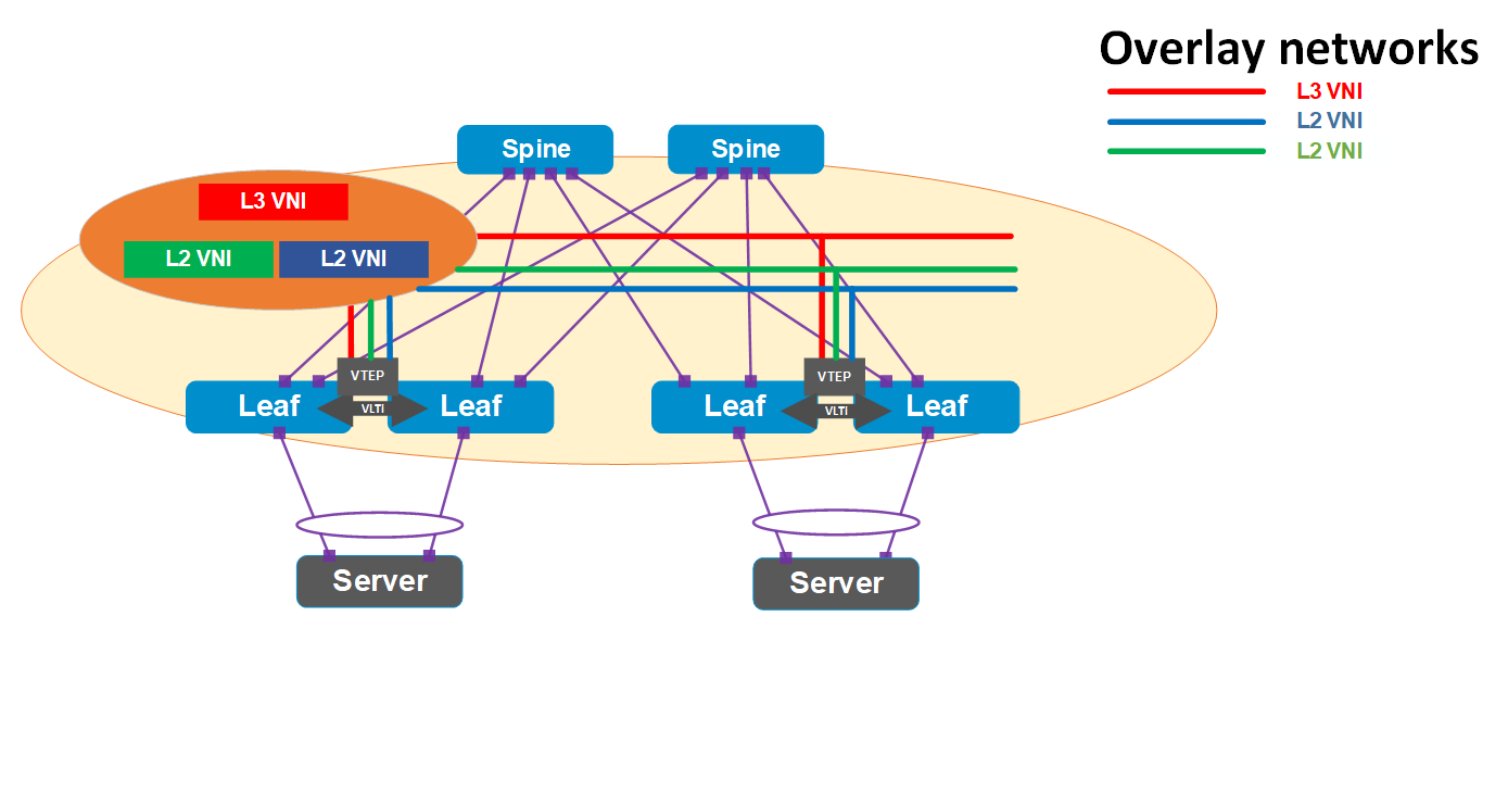
The topology diagram used in this PoC has two spines and four leafs.
Each rack has two leaf switches for performance and redundancy. A Virtual-Link Trunking (VLTi) connects each pair of leaf switches. Each leaf switch has a Layer 3 uplink to every spine switch. Equal-cost Multipathing routing (ECMP) allows the use of all available bandwidth on the leaf-spine connections. Even though VLTi adds additional complexity to the configuration and operation, smaller data centers prefer VLTi because the loss of a rack of servers can be catastrophic.
We have used Ansible BGP EVPN and VXLAN modules to stretch Layer 2 networks across the Layer 3 leaf-spine fabric. Multiple independent instances, either Layer 2 or Layer 3 of a specific tenant, are created, and operate in shared BGP EVPN VXLAN fabric. This provides scalability of the Layer 3 networks with VM mobility benefits of Layer 2 networks. For example, if a VM needs to be moved to another rack, it can be moved without the need to change its address and gateway implementation. With every host connected to two ToR switches, the network becomes resilient to failures, and the load is balanced by dividing data across multiple interfaces.
To learn more about Dell EMC SmartFabric OS10 collections and Ansible deployment, see the Ansible for SmartFabric OS10 – Technical Note.

SmartFabric Services Integration with VMware NSX-T
Tue, 13 Sep 2022 23:30:11 -0000
|Read Time: 0 minutes
SmartFarbic Services (SFS) is automation software that is built into Dell EMC SmartFabric OS10. Open Manage Network Integration (OMNI) is an orchestration appliance that allows for the integration of SFS with various solutions and provides a single pane of management for multiple fabrics and solutions.
Note: For more information on SFS, see the Dell EMC SmartFabric Services blog, or the Dell EMC OpenManage Network Integration (OMNI) blog.
One of the solutions that OMNI is engineered to integrate with is VMware NSX-T Manager. The integration allows OMNI to automatically configure the physical underlay with the specific networking values that have been configured in the NSX-T Manager. The NSX-T Manager is deployed and configured for all relevant values, transport zones, uplink and transport profiles, transport nodes, tier-0 and tier-1 routers, and any segments. Once NSX-T is fully configured, it is integrated with OMNI. OMNI then reads the values in the NSX-T Manager and configures all Layer 3 (L3) VLANs and any BGP routing configurations.
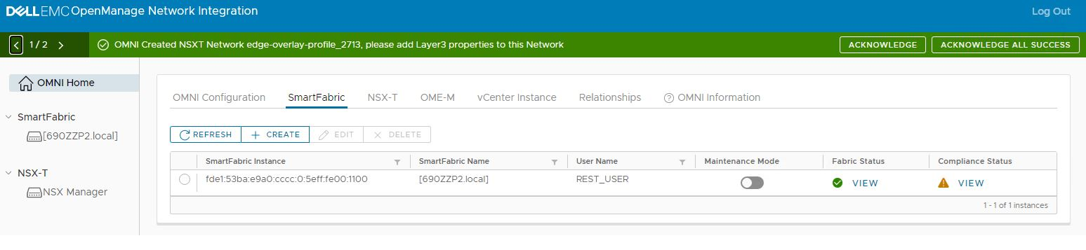
Once OMNI configures the physical underlay with the values pulled from the NSX-T Manager, the user needs to go to the networks section of OMNI and add the relevant IP addresses to the host overlay and edge overlay networks. The required IP addresses for the uplink networks are automatically pulled from the NSX-T Manager and applied to the fabric.
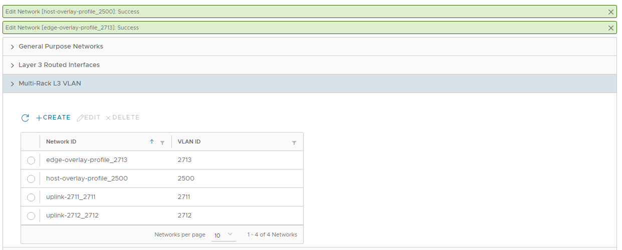 Image Caption
The example topology below uses a leaf-spine fabric for performance and scalability. SFS automates the deployment of this fabric, and OMNI automates the networking requirements for the NSX-T overlay.
NOTE: Step-by-step deployment of the SFS and VxRail environment is detailed in Dell EMC Networking SmartFabric Services Deployment with VxRail Deployment Guide. This NSX-T deployment uses L3 routed uplinks from the leaf switches in Rack 1 to the external switches.
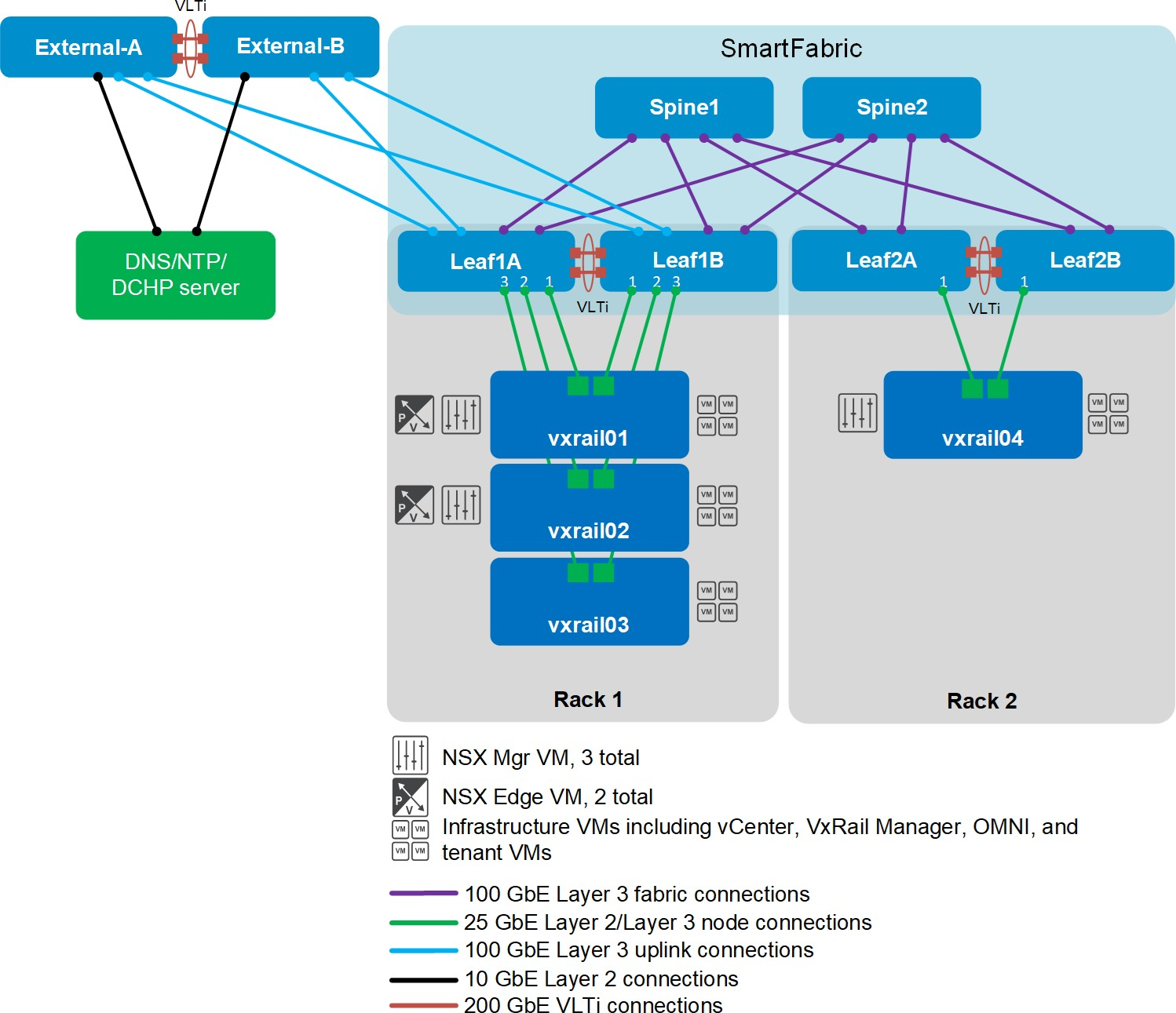 With SFS, two leaf switches are used in each rack for redundancy and performance. A Virtual-Link Trunking interconnect (VLTi) connects each pair of leaf switches. Every leaf switch has an L3 uplink to every spine switch. Equal-Cost Multi-Path routing (ECMP) is leveraged to use all available bandwidth on the leaf-spine connections.
SFS uses BGP-EVPN and VXLAN to stretch Layer 2 (L2) networks across the L3 leaf-spine fabric. This allows for the scalability of L3 networks with the VM mobility benefits of an L2 network. For example, a VM can be migrated from one rack to another without the need to change its IP address and gateway information.
Each VxRail node has two network adapter ports. The ports carry Management, VSAN, vMotion, and NSX-T traffic.
For high-availability, VMware recommends you deploy a cluster of three NSX Manager VMs and a cluster of two NSX Edge VMs. VM host rules are configured to keep the NSX Manager and NSX Edge VMs on separate hosts.
An additional rule is created to keep NSX Edge VMs on hosts that connect to the border leafs. The border leafs provide the physical uplink connections to the external network.
Only the NSX Edge VMs need to be on VxRail nodes in a specific rack. NSX Manager VMs, infrastructure VMs (such as vCenter Server, VxRail Manager, and OMNI), and tenant (or user) VMs may be on VxRail nodes in different racks as needed.

SmartFabric Services vCenter Integration
Thu, 24 Jun 2021 21:31:51 -0000
|Read Time: 0 minutes
Once SmartFabric Services (SFS) is deployed and configured, it is integrated with VMware vCenter through the Open Manage Network Integration (OMNI) appliance.
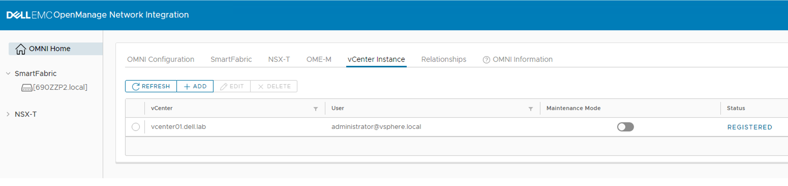
Once vCenter is registered with OMNI, OMNI will read any changes to the virtual distributed switch (vDS) in vCenter and automatically make the associated network configurations on the Fabric.
Below we can see that a new port group has been defined with a VLAN ID of 100.
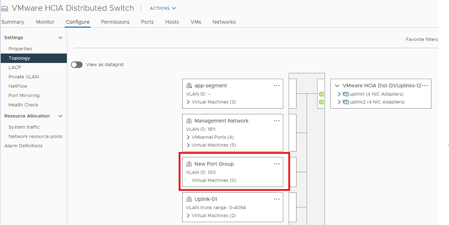
The OMNI vCenter plugin then reads the recent tasks and makes the associated changes on the Fabric. Below we can see that once the port group was created an OS10 SmartFabric update task is initiated. This prompts OMNI to read the change and update the fabric accordingly. In this example, a network with the ID of 100 is created on the switch and applied to all server ports associated with that vDS.
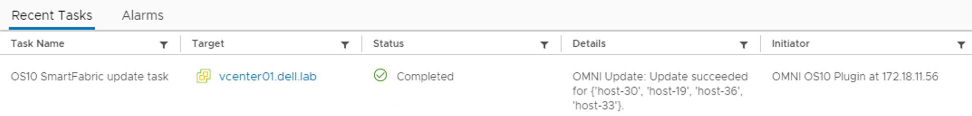
The new network creation and configuration can be verified through vCenter with the OMNI plug-in. When going to an individual host under the monitor tab, there is the option to view the networking with the OMNI vCenter plug-in.
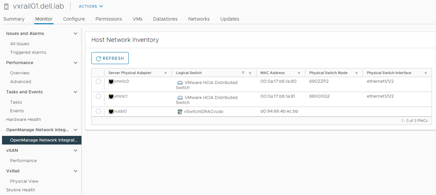
If a specific vmnic is chosen, both the logical networking (vDS port groups) and the physical networking on the fabric can be verified.
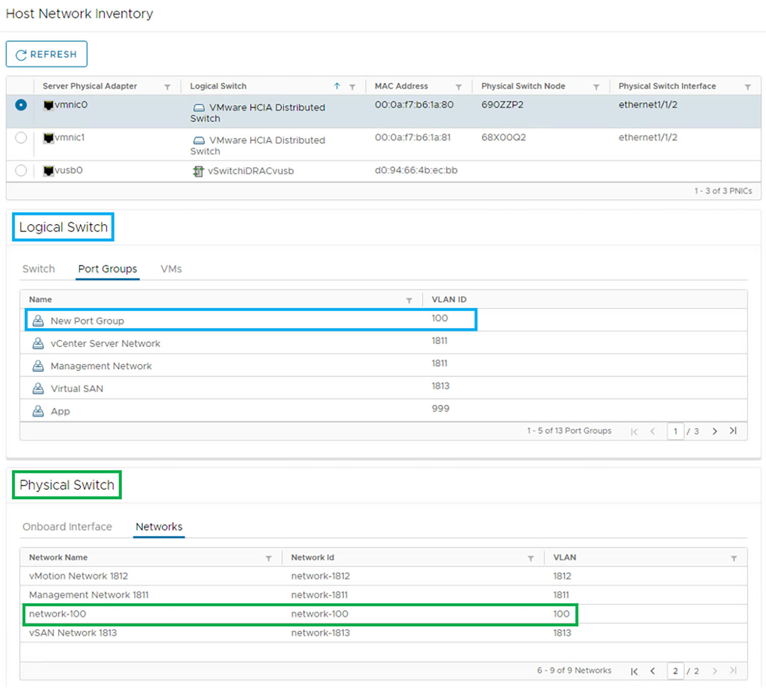

Dell EMC OpenManage Network Integration (OMNI)
Tue, 15 Jun 2021 21:39:21 -0000
|Read Time: 0 minutes
Dell EMC OpenManage Network Integration (OMNI) is a management application that is designed to complement SmartFabric Services (SFS), providing a web-based UI for operating one or more automated network fabrics deployed using SFS (called SmartFabric instances).
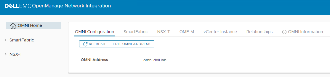
OMNI is delivered as a virtual appliance that can be deployed as:
- A stand-alone virtual machine that enables a web portal to manage one or more SmartFabric Instances
- An external plug-in for VMware vCenter. When deployed as a plug-in for VMware vCenter, OMNI enables:
- Zero-touch automation of physical underlay network fabric running SFS corresponding to changes in the virtual network layer
- Extension of vCenter Host Network Inventory data to include physical switch connectivity details for easy monitoring and troubleshooting
- A single pane of management for one or more SmartFabric instances through the OMNI portal pages that are embedded within vCenter
OMNI allows you to monitor, configure, and troubleshoot the Fabric all from within vCenter with the OMNI vCenter plug-in.
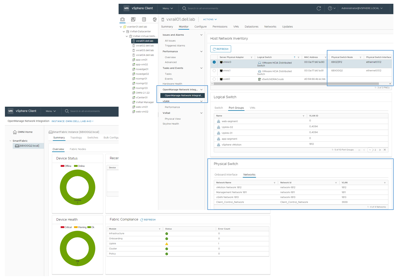
For more information, see OpenManage Network Integration for SmartFabric Services User Guide, Release 2.0.

Dell EMC SmartFabric Services
Wed, 09 Jun 2021 22:12:36 -0000
|Read Time: 0 minutes
SmartFabric Services (SFS) is automation software that is built into Dell EMC SmartFabric OS10. With SFS, customers can quickly and easily deploy and automate data center networking fabrics.
There are two types of SFS:
- SFS for Leaf and Spine – supported on selected PowerSwitch S and Z series switches
- SFS for PowerEdge MX – supported on selected modular switches
SFS for Leaf and Spine has three personalities:
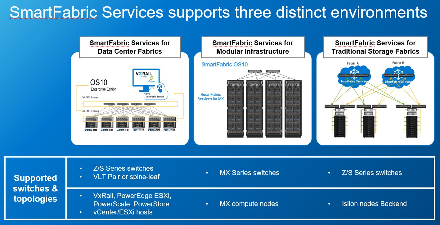 Figure 1. Supported SmartFabric Services environments
SFS for Modular Infrastructure (MX)
A SmartFabric is a logical entity that consists of a collection of physical resources, such as servers and switches, and logical resources such as networks, templates, and uplinks. The OpenManage Enterprise – Modular (OME-M) console provides a method to manage these resources as a single unit.
In the PowerEdge M1000e and FX2 platforms, I/O Aggregation (IOA) was implemented to simplify the process to connect blade servers to upstream networks, so server administrators and generalists could manage uplinks, downlinks, and VLAN assignments without needing to be fluent with the CLI.
Note: See the Dell EMC PowerEdge MX Networking Deployment Guide for more information.
SmartFabric Services mode builds on this IOA functionality providing:
- Data center modernization
- I/O Aggregation
- Plug-and-play fabric deployment
- Single interface to manage all switches in the fabric
- Lifecycle management
- Fabric-wide SmartFabric OS10 updates
- Automated or user-enforced rollback to the last well-known state
- Fabric automation
- Physical topology compliance
- Server networking managed using templates
- Automated QoS assignment per VLAN
- Automated storage networking
- Failure remediation
- Dynamically adjusts bandwidth across all interswitch links if there is a link failure
- Automatically detects fabric misconfigurations or link level failure conditions
- Automatically heals the fabric on failure condition removal
Note: In SmartFabric mode, MX series switches operate entirely as a Layer 2 network fabric. Layer 3 protocols are not supported.
SFS for Data Center Fabrics
VxRail Layer 2 single rack personality
Note: For new single rack and multirack SFS deployments, Dell requires using the Layer 3 Fabric personality instead of the VxRail Layer 2 Single Rack personality.
The VxRail Layer 2 Single Rack personality is the original SFS personality. It is enabled by running a Python script in the OS10 Linux shell.
This personality is limited to a single rack and cannot be expanded to a multirack deployment. If switches with this personality enabled are upgraded, they will continue to operate with the VxRail Layer 2 Single Rack personality.
Layer 3 fabric personality
The Layer 3 Fabric Personality allows users to deploy SmartFabric Services in a single rack and expand to multirack as business needs evolve.
The SFS Layer 3 Fabric personality automatically builds a Layer 3 leaf-spine fabric. This enables faster time to production for hyperconverged and private cloud environments while being fully interoperable with existing data center infrastructure.
Note: For more information, see the Dell EMC SmartFabric Services User Guide, Release 1.0.
Note: For deployment examples using the Layer 3 Fabric personality, see the Dell EMC SmartFabric Services with PowerEdge Servers, PowerStore Storage Appliance, and Isilon Storage Deployment Guide, and the Dell EMC Networking SmartFabric Services Deployment with VxRail 7.0.1 Deployment Guide.
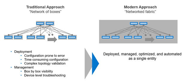 Figure 2. From a network of boxes to a networked fabric
The SFS Layer 3 Fabric build process is as follows:
- Rack and cable leaf and spine switches.
- Enable SFS from the OS10 CLI with the smartfabric l3fabric enable role [options] command.
- Specify the role (leaf or spine)
- Specify Virtual Link Trunking interconnect (VLTi) ports on leafs
- Switches boot in SmartFabric mode.
- Switches discover each other using LLDP.
- Switches elect one of the leaf nodes as the SmartFabric primary.
- Leaf and spine connections are established using private IP addresses and external Border Gateway Protocol (eBGP).
- Leaf Nodes are configured as hardware VTEPs for the infrastructure network overlay using BGP EVPN.
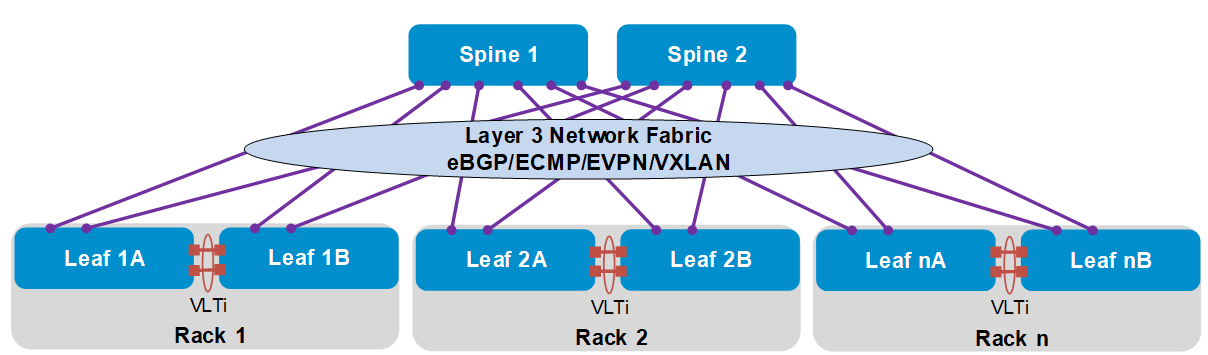 Figure 3. SFS Layer 3 leaf-spine fabric
SFS for traditional storage fabrics
Dell EMC PowerScale is a scale-out network-attached storage (NAS) platform that supports unstructured data workloads. The OneFS operating system powers all the PowerScale models. PowerScale uses Dell EMC PowerSwitch to provide the network. SmartFabric OS10 with SFS, for PowerScale back-end fabric automates onboarding and network configuration of PowerScale devices on a Layer 3 leaf and spine fabric. Isilon OneFS interacts with back-end fabric formed by SFS. For more information, see PowerScale InfoHub.
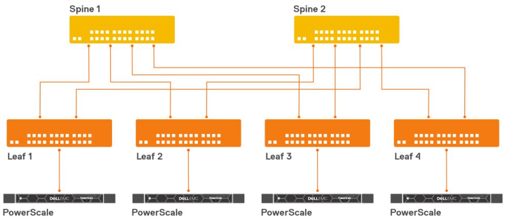
SmartFabric Services for CI/HCI (VxRail)
When deploying the VxRail solution, SFS can be integrated with the VxRail manager to simplify and automate the networks required for VxRail deployment. When additional VxRail Nodes are connected to the SmartFabric, the fabric identifies them as VxRail Nodes and automatically onboards them to the required networks.
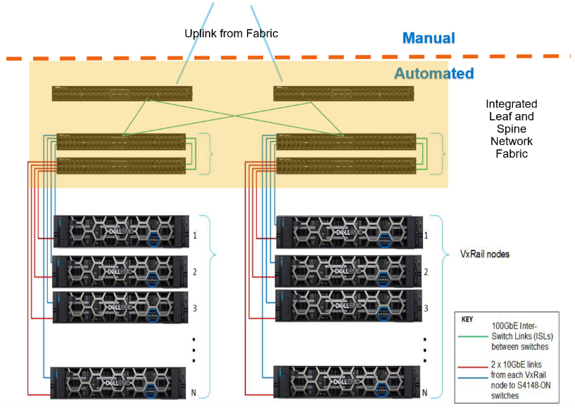
Note: For deployment examples using the SFS/VxRail integration, see the Dell EMC Networking SmartFabric Services Deployment with VxRail 7.0.1 Deployment Guide.

Time Synchronization in Network Devices—the Why and How
Thu, 20 Aug 2020 19:29:29 -0000
|Read Time: 0 minutes
In this post, we will talk about Precision Time Protocol (PTP) and how it goes beyond Network Time Protocol (NTP) to offer better accuracy and time synchronization.
Why?
Let us take the modern wireless network for example - precision timing and synchronization are crucial for basic communication as well as providing the ability to detect location and movement. Although time synchronization plays a prominent role in packet-based networks, it is often implemented as an afterthought.
Every aspect of securing and debugging a network typically involves determining when events happen and accurately correlating log files between network devices. Here are several reasons why time synchronization is important for your network:
- When something goes wrong, you need to look through the log messages to identify the root cause and which device caused it. If your clocks are not synchronized, this becomes a difficult task.
- Manually setting up your clock against a common time source can be time consuming.
- Tracking network usage, latency issues, and security breaches can be impossible if timestamps in logs are inaccurate.
- By synchronizing clocks on network devices, they can act as a time source to other devices in the same network.
How?
There are several time synchronization mechanisms that can be used in a network. The most common ones are Network Time Protocol (NTP) and Precision Time Protocol (PTP). The older and well-known NTP (currently in its fourth version) was primarily developed to achieve accuracy in the submillisecond range and is widely adopted for network timekeeping. Since NTP is based on software timestamping, it can be less accurate for certain industrial applications where greater levels of synchronization are required.
Precision Time Protocol (IEEE 1588 Version 2) is a network-based time synchronization standard designed for distributing precise time and frequency from a clock source over packet-based networks. PTP uses hardware timestamping to achieve submicrosecond accuracy. PTP also enables switches and routers to deliver synchronization with a higher level of accuracy than NTP that is suitable for today’s cloud networks and data center infrastructures. It can be especially useful in industrial and financial applications where microseconds matter. The applications of PTP can be applied to almost any industry, all the way from enterprise data centers to financial sectors, and many more.
To ensure clock synchronization, PTP sends messages between the time source and the receiver to determine the accurate measurement of the path delay. With PTP, time is carried in “event” messages transmitted from a Grand Master (GM), or primary clock, to a secondary clock, and vice versa. The network nodes synchronize to the primary clock, and thus all the clocks are synchronized within a PTP network.
Let us take a brief look at the different network node models that define the hierarchy in the PTP protocol. The Best Master Clock Algorithm (BMCA) runs on all clocks available in the network to determine the best clock.
- Grand Master (GM) is the primary clock source within a PTP domain. It usually has a precise time source, such as a GPS or atomic clock, and functions as the reference clock.
- Boundary Clock (BC) acts as a secondary clock at the port that connects to the primary and distributes time to all other downstream devices. The secondary port synchronizes the time from the upstream PTP device.
- Transparent Clock (TC) forwards the PTP message after updating the residence time of a PTP event message. Ports do not have any state in this clock. A TC on a network only provides support for processing IEEE 1588 Version 2 messages and does not recover time or frequency.
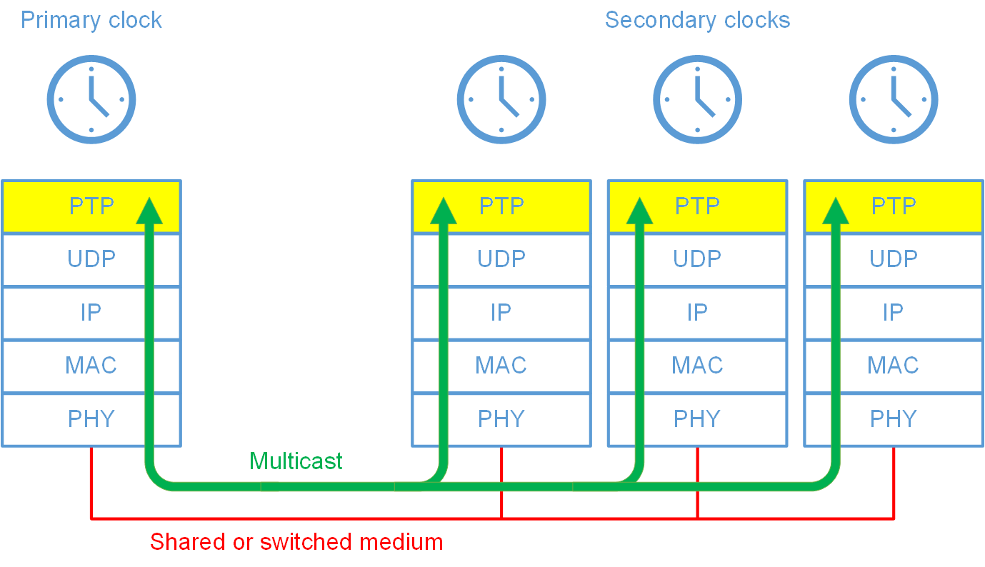
IEEE 1588 Version 2
Did you know that Dell EMC SmartFabric OS10 supports PTP to achieve deeper levels of accuracy? You can configure global and interface-level settings to set up the OS10 switch to function as a PTP device. See the Dell EMC SmartFabric OS10 User Guide to learn more about configuring the boundary clock and transparent clock using different PTP transport methods.
A Network Automation Journey with Ansible—Part 1
Fri, 02 Dec 2022 20:13:24 -0000
|Read Time: 0 minutes
Why Network Automation
Data center networks are being designed and built at a massive scale to support a wide range of applications and services ranging from real-time video, to social media, to augmented reality, and more. Although today’s robust networks are fully capable of running these complex configurations, performing monitoring, and implementing security checks, it is often a tedious task to write manual, CLI-based scripts that are repetitive and subject to human error.
With all the given interdependencies and challenges of today’s networks, the expectations for high performance, availability, and reliability of these networks are higher than ever. By automating everyday network tasks like configuration management and device provisioning, network efficiency and agility of a data center infrastructure can be significantly improved.
Network automation enables the software to automatically provision, configure, manage, and monitor network devices with a minimum number of steps and fewer errors. Automation reduces the complexities of network infrastructure, allowing network administrators to focus more on the innovations of their business needs. The entire network can now be remotely managed without much human intervention. This software-driven architecture is essential for businesses to lower operational costs and improve time-to-market.
The Ansible Story...
Ansible is a simple automation language that can perfectly describe an IT application infrastructure. The same benefits that Ansible brings to compute nodes can now be extended to the network nodes. With Ansible, network teams:
- Use a simple, powerful, and agentless automation framework
- Use a data model (a playbook or role) that easily spans network devices
- Benefit from a wide variety of community and vendor-generated playbook and role content to help accelerate network automation projects
This is why Ansible is a powerful tool that can be utilized to effectively change your day-to-day network operations using automation. Ansible can help teams automate routine tasks and focus on the bigger stuff!
Ansible includes hundreds of network modules, roles, and plug-ins that are now part of Ansible Content Collections to support a wide variety of network vendors. Basically, Ansible Content Collections is a new method of building and consuming Ansible content. It makes deployment automation simpler and smarter, providing a consistent format that allows content creators to ship bundles of modules, plug-ins, roles, and documentation together.
This is how we Role!
The Ansible collection for Dell EMC SmartFabric OS10 includes the modules, plug-ins, and roles required to work on Dell EMC SmartFabric OS10 PowerSwitch platforms running OS10. The Ansible collection for Dell EMC SmartFabric OS10, which includes sample playbooks and documents that illustrate how the collection can be used, is available on Ansible Galaxy.
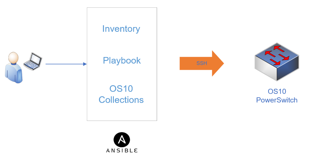
Wondering how to get started ? We’ve got you covered:
- Our Ansible Network Automation hands-on lab shows you everything from installing Ansible to configuring an L3 VXLAN EVPN fabric using the Ansible OS10 collection.
- Our Fabric Design Center allows you to build your own network design in four easy steps and download auto-generated Ansible playbooks for your network configuration. Can’t get easier than this!

Streaming Telemetry with SmartFabric OS10
Tue, 13 Sep 2022 23:30:58 -0000
|Read Time: 0 minutes
As the number of workloads running on massive data center infrastructures increases, network visibility becomes a critical component to prevent any downtimes. The traditional network reporting and monitoring solutions have their limitations because they do not provide enough granularity when you want real-time data to provide end-to-end visibility and performance insights.
Traditional methods such as SNMP use a pull-based mechanism where a management device sends a GET request and pulls data from a client. From a network monitoring standpoint, this model has been successful for a long time but proves insufficient for today’s hybrid cloud infrastructure, where speed, scalability, and reliability are important factors.
Streaming telemetry provides an alternate method by which data is continuously transmitted from network devices using a push-based model. Polling the device and asking for an operational state is not needed. For example, streaming telemetry reports packet drops or high utilization on links in real time. A network automation application can use this information to provision new paths and optimize traffic across the network. The data is encoded using Google Protocol Buffers (GPB) and streamed using Google Protocol RPC (gRPC) transport.
With the current shift to a larger remote workforce, IT teams need to have real-time access to analytics-ready data that can help with network automation, traffic optimization, and preventive troubleshooting.
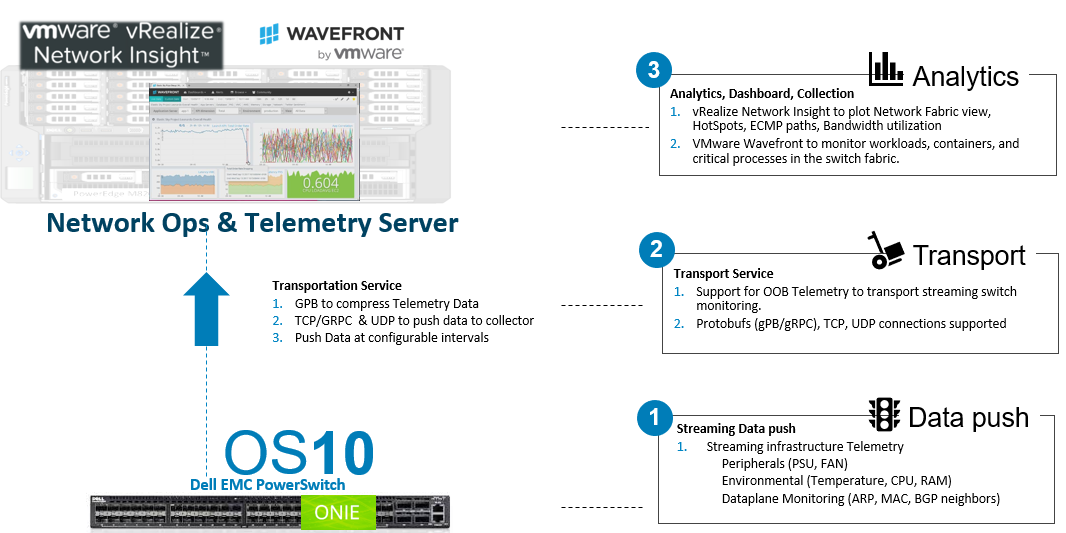
With streaming telemetry, operators subscribe to the specific data they need, using YANG data models as the common structure and interface. Dell EMC SmartFabric OS10 supports streaming telemetry to push telemetry data out to the collectors. The telemetry agent collects data from OS10 applications and switch hardware.
To enable the streaming of telemetry data to destinations in a subscription profile, you need to:
1. Enable telemetry on the switch.
2. Configure a destination group.
3. Configure a subscription profile by associating one or more destination groups and preconfigured sensor groups.
The destination group tells the switch where and how to send telemetry data. The sensor group identifies a list of YANG models that the switch should stream. The subscription profile ties together the destination group and the sensor group. Then, the telemetry agent in the switch attempts to establish a session with each collector in the subscription profile and streams data to the collector.
You can use OS10 telemetry to stream data to:
- Dell-implemented external collectors, such as VMware vRNI or Wavefront
- Proprietary network collectors that you implement
SmartFabric Director, developed by VMware and Dell Technologies, employs telemetry to collect switch operational data and display metrics graphically at both the network fabric and switch levels. SmartFabric Director provides out-of-the-box insights, such as switch health and fabric health that can ensure consistency between the operational state and the intended state.
For more information about how Dell EMC SmartFabric Director enables more agile and simplified central management across both virtual and physical network infrastructures, see SmartFabric Director 101.