


Getting Started with SmartFabric Services
Wed, 14 Sep 2022 18:47:46 -0000
|Read Time: 0 minutes
Dell SmartFabric OS10 includes SmartFabric Services (SFS) at no additional cost. SFS automatically configures a BGP EVPN leaf-spine topology in your data center and provides a web-based user interface for management of the SmartFabric.
A SmartFabric can be as small as two leaf switches in a single rack, or as large as 16 leafs in eight racks with up to four spine switches connecting the leafs between racks.
This article shows you how to quickly build a two-leaf SmartFabric.
Make the VLTi connections
With SFS, you use two leaf switches in each rack for redundancy and performance. SFS automatically configures the leafs as Virtual Link Trunking (VLT) peers. They are connected to each other with physical links that function as the VLT interconnect (VLTi). Be sure to use at least two links for the VLTi to provide fault tolerance. Both leafs in the VLT pair must be the same model. See the Dell Networking Support & Interoperability Matrix for a list of Dell PowerSwitch models that support SFS.
High-bandwidth ports available on the switches are typically used for the VLTi, because the VLTi may be used to carry data traffic in certain failure scenarios. The example shown in this article uses the two QSFP28 2x100GbE Double Density ports available on the Dell PowerSwitch S5248F-ON. These ports are numbered 1/1/49-1/1/52.
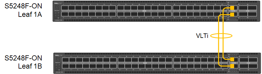 Figure 1 Leaf switch VLTi connections
 Make the OOB Connections
The out-of-band (OOB) management network is an isolated network for remote management of hardware including servers, switches, storage arrays, and other devices using their dedicated management ports. For example, PowerEdge server iDRACs are typically connected to this network.
The OOB management network is required to access the SFS web UI. It also enables switch console access using SSH and is used to carry heartbeat messages between switches that are configured as VLT peers.
At least one switch supporting 1 GbE (1000BASE-T) is required for these connections. Dell Technologies recommends using one N3248TE-ON or S3048-ON in each rack for OOB management connections. The OOB management switch is not part of the SmartFabric.
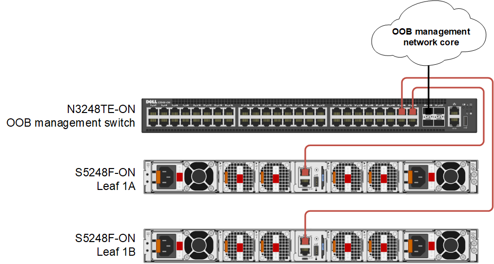 Figure 2 Leaf switch OOB management connections
Change the default passwords
For security, change the passwords of the built-in accounts, admin and linuxadmin, on each switch. The default passwords of these two accounts are admin and linuxadmin respectively. You can use the admin account to log in to the OS10 CLI, the Linux shell, and the SFS UI. You can use the linuxadmin account to log in to the Linux shell.
To change the admin password, connect to the switch console and log in as admin. Run the following commands:
OS10# configure terminal
OS10(config)# username admin password new-password role sysadmin
OS10(config)# exit
OS10# write memory
To change the linuxadmin password, connect to the switch console and log in as admin. Run the following commands:
OS10# configure terminal
OS10(config)# system-user linuxadmin password new-password
OS10(config)# exit
OS10# write memory
Repeat the above steps on the remaining switches.
For additional security best practices, see the Dell SmartFabric OS10 and SmartFabric Services Security Best Practices Guide.
Configure the OOB management IP address
If you don’t use a DHCP server on your OOB management network, configure a unique IP address on the management interface on each switch in the SmartFabric. If you use routing on the OOB management network, you can also configure a management route as shown in this example.
To configure the OOB management IP address, run the following commands on each switch:
OS10# configure terminal
OS10(config)# interface mgmt 1/1/1
OS10(conf-if-ma-1/1/1)# no ip address dhcp
OS10(conf-if-ma-1/1/1)# ip address 100.67.76.12/24
OS10(conf-if-ma-1/1/1)# no shutdown
OS10(conf-if-ma-1/1/1)# exit
OS10(config)# management route 100.67.0.0/16 100.67.76.254
OS10(config)# end
OS10# write memory
Put the switches in SmartFabric mode
Dell PowerSwitches running OS10 are in Full Switch mode by default. All leaf and spine switches in a SmartFabric must be running in SmartFabric mode. The command used to put a leaf switch in SmartFabric mode is in the following format:
smartfabric l3fabric enable role LEAF vlti ethernet VLTi_port_range
When a switch is placed in SmartFabric mode, most of the existing switch configuration is deleted. Some global settings such as the management IP address, management route, and hostname are retained. Be sure the physical VLTi connections are made before running the command.
The leaf switches in Figure 1are put in SmartFabric mode by running the following commands on each switch:
OS10# configure terminal
OS10(config)# smartfabric l3fabric enable role LEAF vlti ethernet 1/1/49-1/1/52
Reboot to change the personality? [yes/no]:y
The configuration is applied, and the switch reloads.
After reloading, you can run the following command on each switch to verify they are each in SmartFabric mode:
OS10# show switch-operating-mode
Switch-Operating-Mode : Smart Fabric Mode
Connect to the SFS UI
From a workstation with access to the OOB management network, use a browser to connect to the management IP address of either leaf switch by going to https://OOB_mgmt_ip_address. Log in as admin.
(After reloading the switches, it will take a few minutes before the UI is accessible.)
All SFS UI configuration is performed on the leader switch. If you connect to a switch in SmartFabric mode that is not the leader, a link to the leader is provided, outlined in red below.
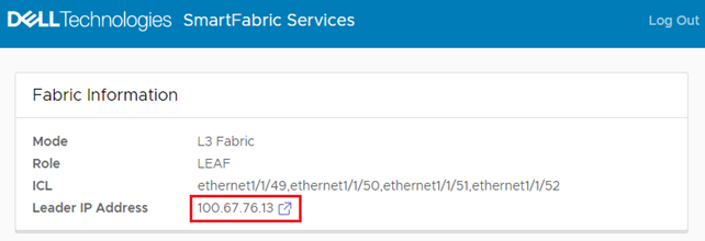 Figure 3 Connected to a switch that is not the leader
If applicable, click the link that is provided to go to the leader switch, and log in as admin.
(You can also find the IPv4 address of the leader switch by running the show smartfabric cluster command from the CLI of any switch in the SmartFabric.)
When connected to the SFS leader switch, the Summary > Overview page displays.
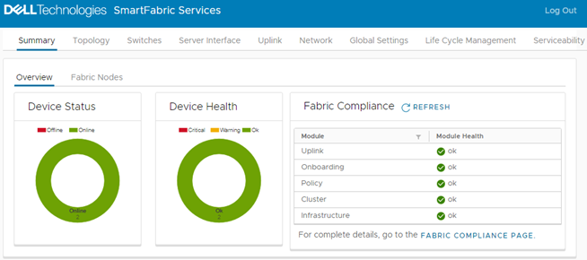 Figure 4 SFS user interface on leader switch
The Device Status box shows that there are two switches in the SmartFabric, and both are Online. The Device Health box shows that both switches are Ok.
You can perform the following tasks in the SFS UI:
- View the fabric status, health, and topology.
- Modify port settings: Set administrative state (up or down), configure MTU, enable or disable auto negotiation, configure breakout ports, and configure a jump port.
- Create server interface profiles and assign ports to networks.
- Create uplinks, including the new multisite fabric interconnect.
- Create networks and configure routing.
- Configure SmartFabric switch global settings: Configure NTP, DNS, SNMP, and Syslog servers, and modify default fabric settings such as ASNs and fabric IP addresses.
- Restore the fabric from a backup.
- Monitor fabric compliance.
The next steps are to onboard your server and storage devices to the SmartFabric, configure uplinks to your existing data center network, and deploy OpenManage Network Integration (OMNI). You can also expand your SmartFabric to additional racks by adding spines and additional leaf pairs as needed.
These tasks and others are covered in the deployment guides and user guides that are listed in the Resources section below.
Resources
SmartFabric Services: Onboarding Devices Using the Import From Fabric Method
SmartFabric Services: Static Onboarding
Dell EMC Networking SmartFabric Services Deployment with VxRail 7.0.240
Related Blog Posts
SmartFabric Services: Static Onboarding
Wed, 14 Sep 2022 21:47:22 -0000
|Read Time: 0 minutes
SmartFabric Services (SFS) automates the configuration of a leaf-spine topology in your data center and provides a web-based user interface for SmartFabric configuration. If you have not built a SmartFabric, see Getting started with SmartFabric Services.
This article is intended to help you quickly onboard devices such as servers and storage arrays to your SmartFabric using the static onboarding method. This method is used if the NICs in the device being onboarded do not support LLDP. If your NICs support LLDP, see SmartFabric Services: Onboarding devices using the Import from Fabric Method.
Connect the device to the leaf switches
With SFS, two leaf switches are used in each rack. Each server or storage device in the rack should have at least one NIC port that is connected to each leaf for redundancy and performance. The NICs may be configured for LACP or a switch independent teaming method.
For the example in this article, a two-leaf SmartFabric has been deployed using a pair of Dell PowerSwitch S5248F-ON switches. A PowerEdge server is connected to port 1/1/11 on each switch, and two 25GbE NIC ports on the server are configured for LACP in the server’s operating system.
 Figure 1 PowerEdge server connected to leaf switches
Dell Technologies recommends connecting dedicated device management ports, such as the PowerEdge server iDRAC, to the OOB management network. The OOB management network uses a separate switch and is required for SFS. See Getting started with SmartFabric Services for more information about the OOB management network.
SFS default networks
SFS has two default virtual networks, numbered 4091 and 3939. Virtual network 4091 is the “Client Management Network” in SFS and is available for general use. Virtual network 3939 is the “Client Control Network” and is used for VxRail node discovery.
You can run the show virtual-network command at the leaf switch CLI to view the existing networks and port assignments.
Create additional networks
As devices are statically onboarded to the SmartFabric, their network assignments are made.
To create one or more networks before onboarding devices:
- From a workstation with access to the OOB management network, use a browser to connect to the management IP address of the SmartFabric leader switch.
- Log in as admin.
- In the SFS UI, select Network > Networks and expand General Purpose Networks.
- Click +CREATE.
- Enter a Network ID, a Network Name, and a VLAN number for the network. The VLAN number can be in the range 1 through 3999, excluding 3939. The VLAN number is also configured as the virtual network number by SFS.
 Figure 2 Creating a Layer 2 network
- Click CREATE.
When complete, a green Success message is displayed and the newly created virtual network appears in the General Purpose Networks list.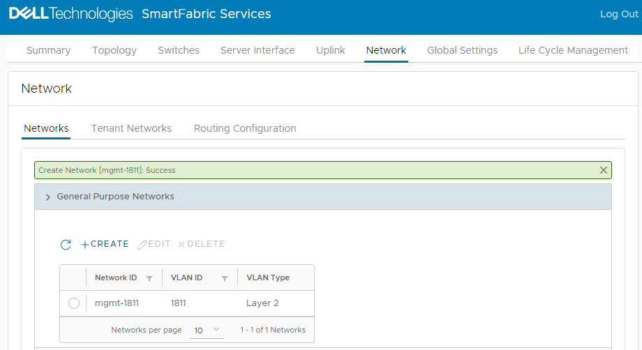 Figure 3 Virtual network 1811 created
To create additional networks as needed, repeat the steps above.
Onboard devices
If you will use OMNI vCenter integration with SFS, you will need the MAC address of each ESXi host NIC that is connected to the leaf switches. OMNI vCenter integration is a feature where ESXi hosts connected to the SmartFabric are automatically added to the correct networks as port groups are created in vCenter. See the OpenManage Network Integration User Guide Release 3.1 for more information. On PowerEdge servers, MAC addresses can be determined using the iDRAC.
If the device you are onboarding is running an operating system other than ESXi, or you will not be using OMNI vCenter integration, the MAC addresses are not required.
Ensure the device being onboarded is connected to the SmartFabric leaf switches and powered on. In this example, the server shown in Figure 1 is onboarded to the SmartFabric.
- In the SFS UI, select the Server Interface tab.
The Server Interface Profilepage displays. Figure 4 Server Interface Profile page
 - Under Server Interface Profile, click +CREATE.
The Create Server Interface Profile page displays.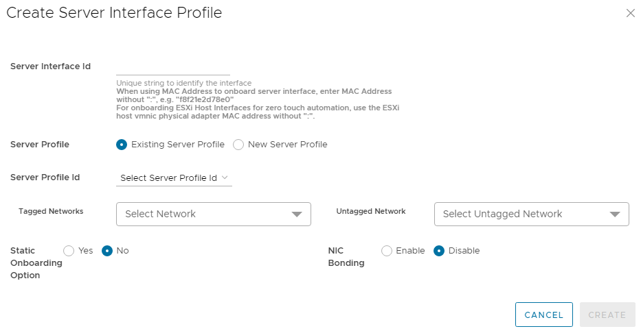 Figure 5 Create Server Interface Profile page
 - Enter a Server Interface ID.
This ID can be a string that you create such as “Server1-NIC1” or the MAC address of the connected NIC. If the MAC address is used, enter it without colons or dashes, as shown in Figure 6. The MAC address is required if you are using OMNI vCenter integration. - Select New Server Profile.
- Next to Server Profile ID, enter a profile name, such as lacp-profile.
- Next to Server Profile Bonding Type, LACP is selected for this example.
- Next to Untagged Network, select the network created earlier, 1811.
You can also select one or more networks from the Tagged Networks as needed. This is not done in this example. - Next to Static Onboarding Option, select Yes.
- Next to NIC Bonding, select Enable since LACP is used in this example.
- Select the Leaf Node and the Interface that the NIC is connected to.
- Leave Routing Protocol set to None.
The page for the first interface appears as shown: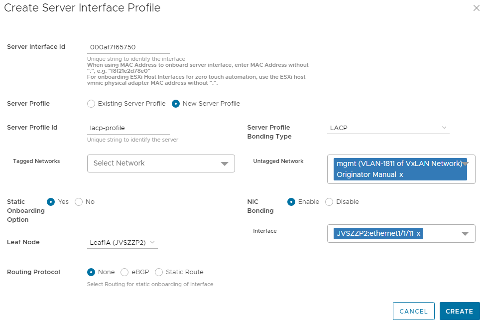 Figure 6 Server profile settings for the first interface
- Click CREATE.
The Server Interface Profilepage lists the interface.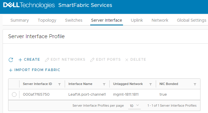 Figure 7 First interface onboarded
Because this example uses LACP, port-channel1 is automatically added to the interface name by SFS. (In SFS, port channels are automatically numbered and start with 1.) If the Server Interface Profile page still shows the interface name as ethernet1/1/port-number, allow a few seconds for the port channel to come up. Also ensure that LACP has also been configured on the server. Click the  icon to refresh as needed.
The second interface is onboarded as follows:
- Under Server Interface Profile, click +CREATE. The Create Server Interface Profile page displays.
- Enter a Server Interface ID.
- Select Existing Server Profile.
- Next to Server Profile ID, select the existing profile from the drop-down list (in this example, lacp-profile).
- Next to Untagged Network, select the network created earlier: 1811.
- Next to Static Onboarding Option, select Yes.
- Next to NIC Bonding, select Enable since LACP is used in this example.
- Select the Leaf Node and the Interface that the NIC is connected to.
- Leave Routing Protocol set to None.
The page for the second interface appears as shown:
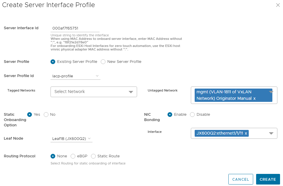 Figure 8 Server profile settings for the second interface
- Click CREATE.
When complete, the Server Interface Profile page lists both interfaces. Click the  icon to refresh the page if needed.
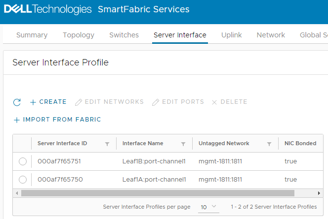 Figure 9 Interfaces onboarded
The server is now onboarded to the SmartFabric.
Resources
Dell EMC Networking SmartFabric Services Deployment with VxRail 7.0.240
SmartFabric Services: Onboarding Devices Using the Import From Fabric Method
Wed, 14 Sep 2022 21:47:22 -0000
|Read Time: 0 minutes
SmartFabric Services (SFS) automates the configuration of a leaf-spine topology in your data center and provides a web-based user interface for SmartFabric configuration. If you have not built a SmartFabric, see Getting started with SmartFabric Services.
This article is intended to help you quickly onboard devices such as servers and storage arrays to your SmartFabric using the Import from Fabric method. To use this method, the NIC connected to the leaf switches must have LLDP enabled. If your NIC does not support LLDP, you can use the static onboarding method that is covered in SmartFabric Services: Static Onboarding.
Usually, LLDP is enabled by default on NICs that support it. It is possible to disable LLDP in the server BIOS, so be sure to check your settings and documentation if SFS does not see the NIC. As an alternative, you can use the static onboarding method even if your NIC supports LLDP. However, the Import from Fabric method is easier.
Connect the device to the leaf switches
With SFS, two leaf switches are used in each rack. Each server or storage device in the rack should have at least one NIC port connected to each leaf for redundancy and performance. The NICs may be configured for LACP or a switch independent teaming method.
For the example in this article, a two-leaf SmartFabric has been deployed using a pair of Dell PowerSwitch S5248F-ON switches. A PowerEdge server is connected to port 1/1/11 on each switch, and two 25GbE NIC ports on the server are configured for LACP in the server’s operating system.
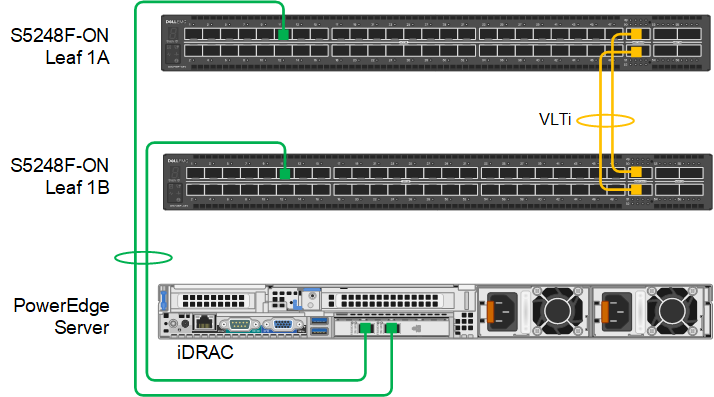 Figure 1 PowerEdge server connected to leaf switches Dell Technologies recommends connecting dedicated device management ports, such as the PowerEdge server iDRAC, to the OOB management network. The OOB management network uses a separate switch and is required for SFS. See Getting started with SmartFabric Services for more information about the OOB management network.
SFS default networks
SFS has two default virtual networks: 4091 and 3939. Leaf switch ports connected to servers with LLDP-enabled NICs are automatically untagged in virtual network 4091 by SFS. Virtual network 4091 is named “Client Management Network” in SFS. If you are using VxRail, SFS also automatically tags ports that are connected to VxRail nodes in virtual network 3939 for node discovery.
You can run the show virtual-network command at the leaf switch CLI to view the existing networks and port assignments.
Create additional networks
As devices are onboarded to the SmartFabric using the Import from Fabric method, their network assignments can be changed.
To create one or more networks before onboarding devices:
- From a workstation with access to the OOB management network, use a browser to connect to the management IP address of the SmartFabric leader switch.
- Log in as admin.
- In the SFS UI, select Network > Networks and expand General Purpose Networks.
- Click +CREATE.
- Enter a Network ID, a Network Name, and a VLAN number for the network. The VLAN number can be in the range 1 through 3999, excluding 3939. The VLAN number is also configured as the virtual network number by SFS.
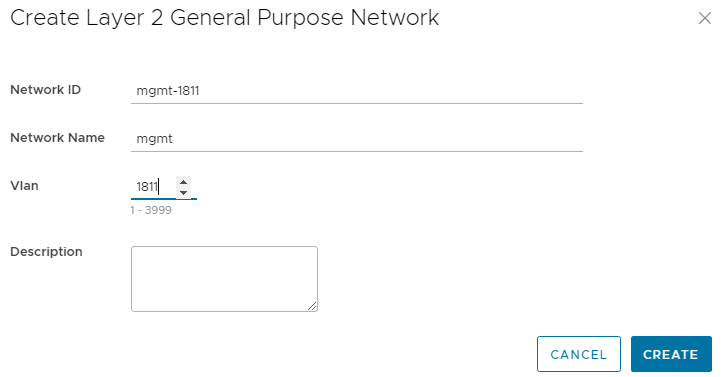 Figure 2 Creating a Layer 2 network
 - Click CREATE.
When complete, a green Success message is displayed and the newly created virtual network appears in the General Purpose Networks list. Figure 3 Virtual network 1811 created
To create additional networks as needed, repeat the steps above.
Onboard devices
Ensure the devices being onboarded are connected to the SmartFabric leaf switches and powered on. In this example, the server shown in Figure 1 is onboarded to the SmartFabric.
- In the SFS UI, select the Server Interface tab.
The Server Interface Profile page displays.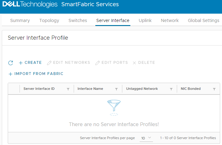 Figure 4 Server Interface Profile page
- Under Server Interface Profile, click +IMPORT FROM FABRIC.
The Discovered Server Interface page displays.
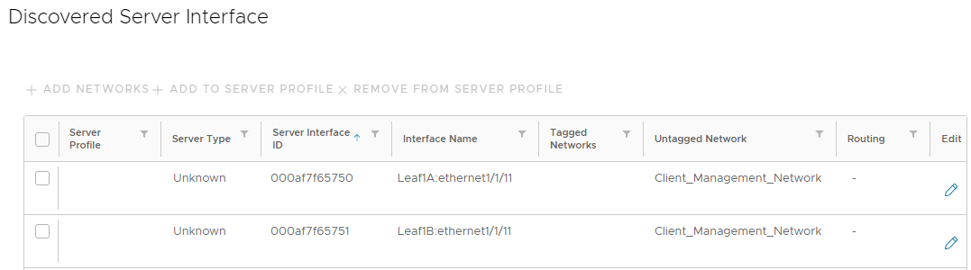 Figure 5 Discovered server interface page
Connected LLDP-enabled devices that are not yet onboarded appear in the list of discovered interfaces.
Identify the server by the ports that it is connected to (ethernet1/1/11 on both leafs in this example). The ports are shown in the Interface Name column. You can also identify the server by the MAC addresses of the connected NICs if they are known. The addresses are shown in the Server Interface ID column.
The ports are untagged in the Client_Management_Network, virtual network 4091, by default. The Server Type is Unknown. (Known server types are VxRail, PowerScale, and PowerMax devices. All other devices are classified as Unknown.)
- Check the boxes next to both server interfaces and click +ADD TO SERVER PROFILE.
- In the Server Profile dialog box:
- Select New Server Profile.
- Next to Server Profile ID, enter a profile name, such as lacp-profile.
- The Bonding Type is set to LACP for this example.
The page appears as shown: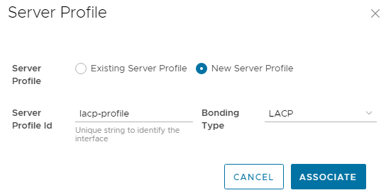 Figure 6 Server profile settings
- Click ASSOCIATE. The new server profile, named lacp-profile, is associated with the two server interfaces.
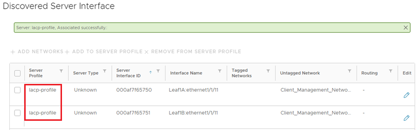 Figure 7 Interfaces added to server profile
- To change the networks that the interfaces are in, check the boxes next to both interfaces and click +ADD NETWORKS.
For this example, the untagged network is changed from the Client_Management_Network to the new network, 1811, as follows:
- In the Add Server Interface Networks window, next to Untagged Network, select network 1811. (One or more networks can also be selected from the Tagged Networks as needed. This is not done in this example.)
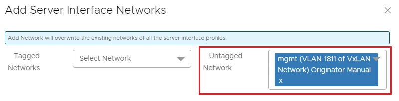 Figure 8 Network 1811 selected
- Click ADD.
The Discovered Server Interface page appears as shown. The interfaces are now untagged in network 1811.
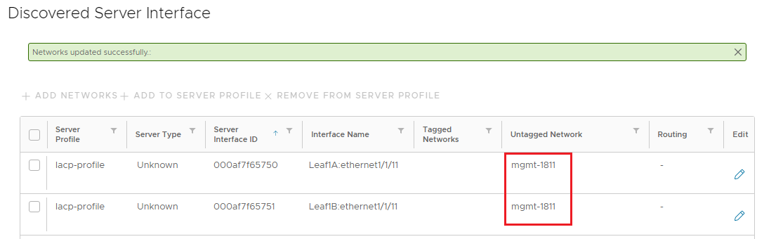 Figure 9 Untagged network changed to mgmt-1811
- Click the box next to both interfaces and click CREATE to apply the configuration.
- In the Importing Server Interface Profiles window, a success message is displayed for each interface.
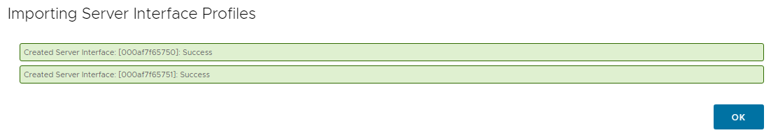 Figure 10 Success messages
- Click OK.
The onboarded interfaces appear in the Server Interface Profile list.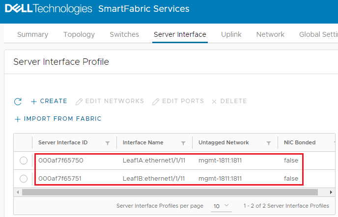 Figure 11 Interfaces onboarded
Because LACP is used in this example, NIC bonding must be enabled.
- Select the first interface and click EDIT PORTS.
- In the Edit Server Interface Profile window, set NIC Bonding to Enable. Leave the Static Onboarding Option set to No.
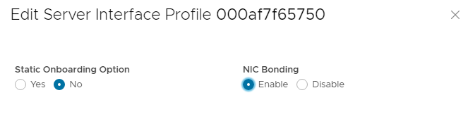 Figure 12 NIC Bonding set to Enable
 - Click EDIT to apply the change.
- Repeat steps 12 through 14 for the second interface.
When complete, the screen appears as shown. Click the icon on the Server Interface Profile page to see the changes as needed.
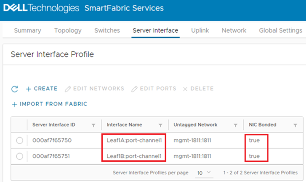 Figure 13 Interfaces configured for LACP
Because this example uses LACP, the interface name has automatically changed from ethernet1/1/11 to port-channel1. (In SFS, port channels are automatically numbered and start with 1). If it has not changed, LACP also needs to be configured on the server for the port channel to appear in the list. NIC Bonded is set to true for both interfaces.
The server is now onboarded to the SmartFabric.
Resources
Dell EMC Networking SmartFabric Services Deployment with VxRail 7.0.240