


Dell Technologies - A Tale of Two Fabrics
Tue, 13 Sep 2022 23:21:53 -0000
|Read Time: 0 minutes
Whenever we take public transportation or go to an airport, theater, mall, or restaurant, we feel the constant pull of our phones and other digital devices.
We feel the need to stay connected. The vast amount of information that is generated by this need has created a unique set of requirements for the telecommunication industry and its related services or application infrastructure.
The typical 3-tier networking architecture—access, distribution, and core—have evolved into a simple and scalable leaf and spine architecture. As the environment grows horizontally and application availability is needed across different data centers, there are multiple options available:
- Deploy a new leaf and spine fabric and interconnect to existing fabric.
- Add more leaf and spine switches to the existing leaf and spine environment.
This blog focuses on how the deployment of a new leaf and spine fabric can sometimes create the need for different interconnected options.
Figure 1 shows a distributed Clos architecture that is bound by EVPN BGP VXLAN. This architecture consists of an underlay and an overlay. Figure 1 also shows a single EVPN fabric in a data center. The underlay is the physical infrastructure of leaf and spine switches, while the overlay is the implementation of EVPN BGP VXLAN. VXLAN allows Layer 2 domains to be stretched across a Layer 3 cloud implemented by EVPN BGP.
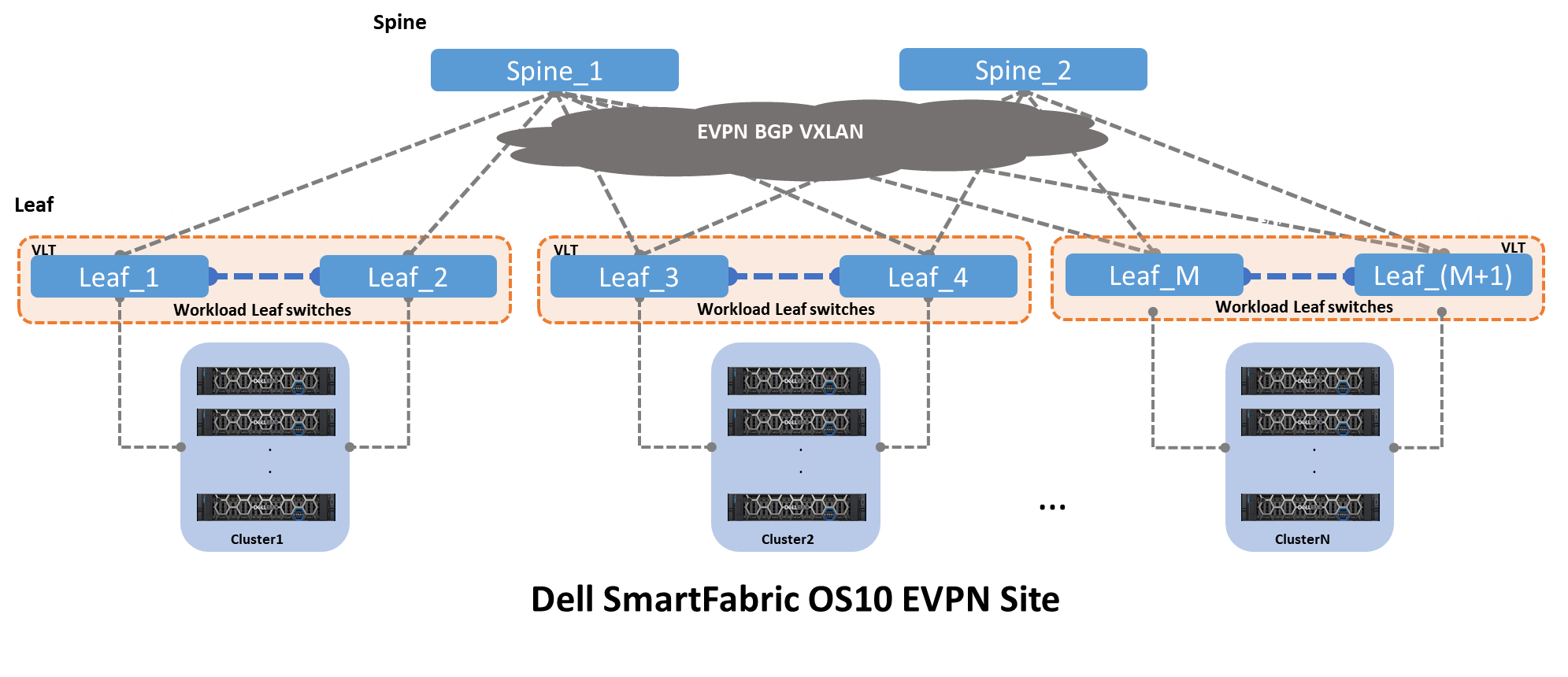
Figure 1 – Clos leaf and spine architecture with EVPN BGP VXLAN
The underlay is the physical infrastructure of leaf and spine switches, while the overlay is the implementation of EVPN BGP VXLAN.
VXLAN allows Layer 2 domains to be stretched across a Layer 3 cloud implemented by EVPN BGP.
Two key drivers create a need for a single EVPN fabric to connect to another EVPN fabric:
- Performance limitation within a single EVPN fabric
- Application availability across two or more distinct EVPN fabrics
Figure 2 shows the same architecture that is shown in Figure 1, plus the interconnect options and origins. From the spine switches, the most common type of deployment is a pure Layer 3 point-to-point. And from the leaf switches, three different deployments are seen:
- Layer 2 as trunks carrying all VLANs
- Layer 3 point-to-point
- Hybrid, that is a LAG with an IP address
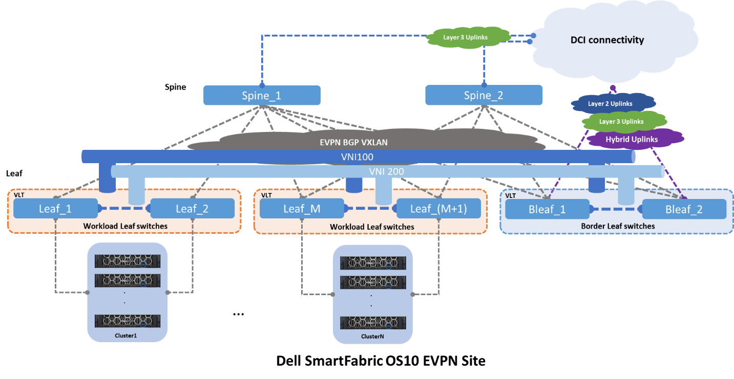
Figure 2 – EVPN BGP leaf and spine with uplinks
Fabric Interconnects
The Dell Technologies EVPN implementation provides three different interconnect options. Each of these interconnects leverages a different set of features and design guidelines.
Option 1 - Multisite EVPN with direct links
Figure 3 shows option 1, where two EVPN sites or Point of Delivery (PoDs) interconnect by direct links from the leaf switches. These links can be configured as Layer 2 or Layer 3.
If Layer 2 links are used, these links are configured as “trunks” carrying all the networks or VLANs from Site1 to Site2. This option is easy to implement and well understood, however it is prone to scalability limitations and other Layer 2
If Layer 3 links are used, these links are configured as traditional point-to-point with an IP address. The border leaf switches act as Layer 2 termination points or gateways for the networks that are defined by the workloads.
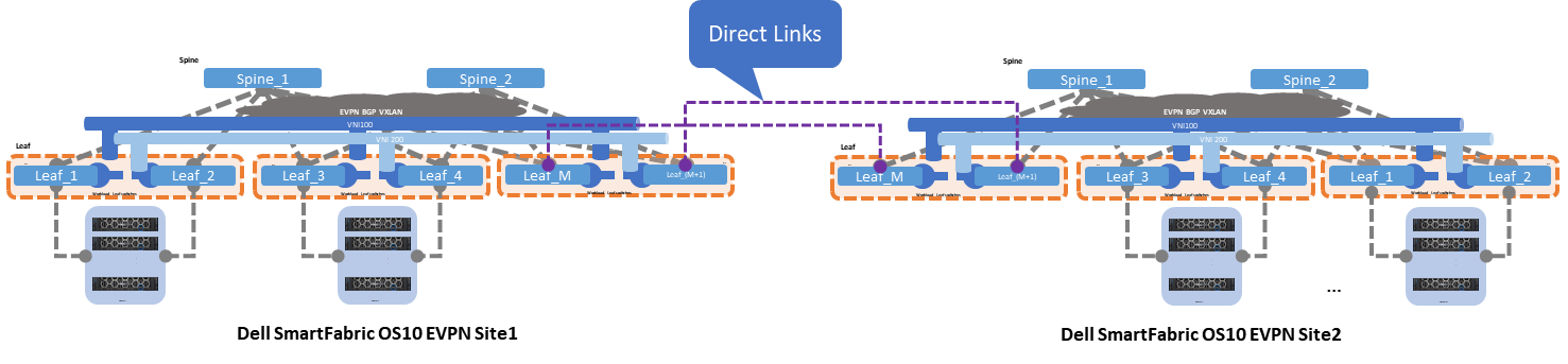
Figure 3 – Multisite EVPN with direct links
Direct links are deployed using dark fiber or some sort of patch panel, and the EVPN sites are less than 10 kilometers long. This connectivity option is often the simplest and most straightforward, but as the number of interconnects grows, this option can become difficult to manage.
The following characteristics summarize option 1:
- Interlinks (Leaf-to-Spine) speed 10/25GE
- Layer 2 interlinks
- Direct (inser-site) links speed 100GE
- Direct-link type Layer 2 or Layer 3
- Easy to implement but subject to scalability and management growing pains
Option 2 - Multisite with super spine links
The second option shows two EVPN sites that are interconnected by super spine switches. The super spine switch acts as a direct inter-site hand-off, offloading any unnecessary network traffic from the standard spine connected to the leaf switches.
Figure 4 shows the standard spine switches focusing on inter-rack traffic, whereas the super spine switches focus on inter-site traffic switching.
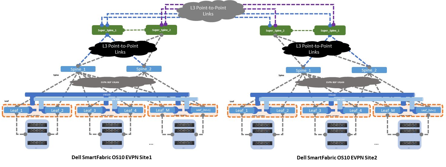
Figure 4 – Multisite EVPN with super spine link
The following characteristics summarize option 2:
- Interlinks (leaf-to-spine) speed 10/25GE
- Layer 2 interlinks (leaf to spine)
- Core links (spine-to-super spine) and (super spine-to-super spine) speed 100GE
- Layer 3 core links point-to-point
- ECMP on core links
- Moderate to implement as it requires good Layer 3 knowledge
- Better scalability
Option 3 - Multisite with indirect links
The last and third option shows two EVPN sites that are interconnected by indirect links. These links originate at the leaf switches and connect to an upstream router or switch using three different uplink deployment models:
- Layer 2
- Layer 3
- Hybrid
Layer 2 uplink
When a Layer 2 uplink is used to connect to the data center interconnect (DCI) cloud, this uplink carries only Layer 2 traffic. The uplink is configured as a “trunk” carrying multiple VLANs towards the DCI cloud. This uplink type provides link redundancy and load-balancing benefits when configured as a link aggregation (LAG).
The DCI cloud terminates all Layer 2 traffic and is configured as an EVPN BGP VXLAN overlay stretching all Layer 2 domains.
Layer 3 uplink
When a Layer 3 uplink is used to connect to the DCI cloud, the uplink is configured as a straight point-to-point Layer 3. This uplink type provides redundancy and load balancing when equal cost multipathing (ECMP) and different hashing algorithms are configured.
The DCI cloud is configured as an EVPN BGP VXLAN overlay stretching all Layer 2 domains from site to site.
Hybrid uplink
For the hybrid uplink, a LAG is configured between the border leaf switches and the upstream DCI router or switch. VRFs are used to isolate traffic type within a single tenant, and the border leaf switches point to the upstream DCI device as the default exit point.
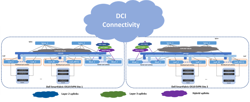
Figure 5 – Multisite EVPN with indirect links
Data will continue to increase, and the number of data centers will increase proportionally. Dell Technologies gives customers options on how to interconnect these data centers. The options that are discussed in this blog provide a basic reference, and they should be used as a starting point for any EVPN discussions.
Resources
Dell Technologies EVPN User Guide
Related Blog Posts

Be more agile with EVPN Multihoming (MH)
Thu, 04 Jan 2024 16:51:10 -0000
|Read Time: 0 minutes
Let’s talk about enhancing your basic EVPN fabric. In your typical data center EVPN fabric, an end host uses dual homed connections onto the leaf or Top of Rack (ToR) switches.
The ToRs are usually a pair of switches configured with multi-chassis link aggregation (MC-LAG) to provide end-host link redundancy if one of the ToRs failed.
These links are Layer 2 with spanning-tree deployed on the fabric. Spanning tree typically blocks half of the links to avoid any network loops. As a result, the fabric bandwidth is cut in half. This only happens when the LAG consists of single links, as demonstrated in Figure 2.
However, if there was a way to attain link redundancy, flexibility, and full link bandwidth utilization things could be more interesting in the EVPN landscape.
Dell Enterprise SONiC 4.2 brings EVPN multihoming into the data center. It is a standards-based replacement for multi-chassis link aggregation (Multi-chassis Link Aggregation Group) and legacy stacking technology.
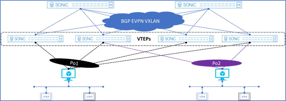
Figure 1. Dell Enterprise SONiC EVPN MH
Figure 1 shows the supported Dell Enterprise SONiC EVPN MH deployment. It shows the maximum number of VTEPs that can be connected to a single end host.
These connections are independent, meaning each link belonging to the link aggregation (LAG) can be connected to multiple independent upstream switches and these upstream switches do not have to be interconnected.
Deployment simplicity is the main benefit of EVPN MH, as all the connections only have to be connected from the end-host or server to the switches.
Achieve end host enhanced connectivity and link efficiency with EVPN MH
In an EVPN fabric, especially a data center fabric, the end hosts or servers are dual homed to a pair of Top of Rack (ToR) switches providing link redundancy. This deployment is common and it uses MC-LAG.
The other deployment option is known as stacking. This option involves several switches stacked together with a primary switch acting as the controller of the stack. All end-hosts or servers are connected to each of the switches part of the stack.
Note: A stack consisting of a single switch is also possible, but rarely deployed.
Both deployments offer link and device redundancy, but they have some limitations that EVPN MH can overcome. The benefits and limitations for each deployment option are described in the following lists.
MC-LAG deployment
- A minimum of two ToR/Leaf switches are required
- A single switch deployment is not supported
- An end host or server can connect only up to two ToRs/Leaf switches at any given time
- All connections from the end-host or server are Layer 2 based
Stacking deployment
- A maximum of eight switches are stacked with one primary or controller switch
- Specific types of stacking cables are required to form the stack
- A single switch deployment is not supported
- All end hosts or servers connect to each switch part of the stack to maintain link redundancy, resulting in a cable management situation
- All connections from the end-host or server are Layer 2 based
EVPN multihoming deployment
- A minimum of one ToR/Leaf switch is required
- An end-host or server can connect to four separate ToR/Leaf switches (VTEPs) at any given time
- All links from the end-host or server to the VTEPs are active
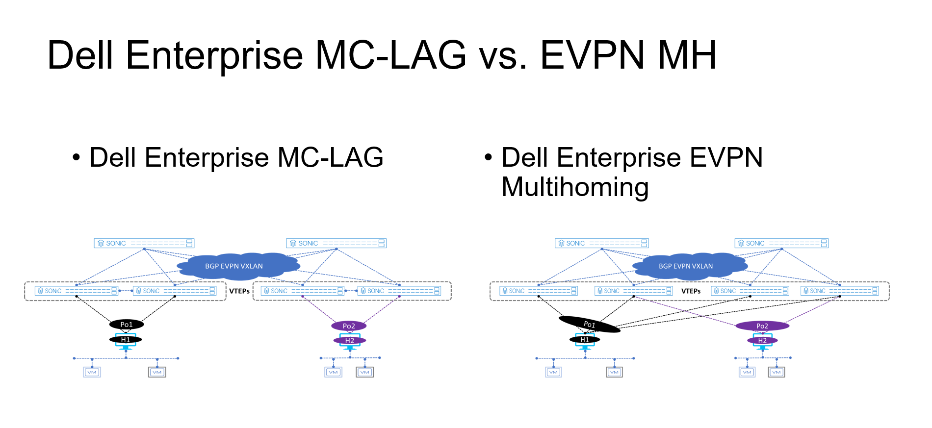
Figure 2. MC-LAG vs. EVPN multihoming deployment
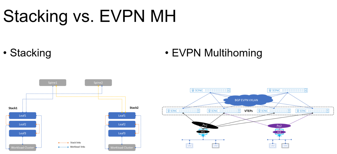
Figure 3. Stacking vs. EVPN multihoming deployment
The advantages offered by EVPN multihoming are clear when compared with the traditional stacking and MC-LAG. Table 1 summarizes these differences.
Table 1. Stacking compared to MC-LAG and EVPN-MH
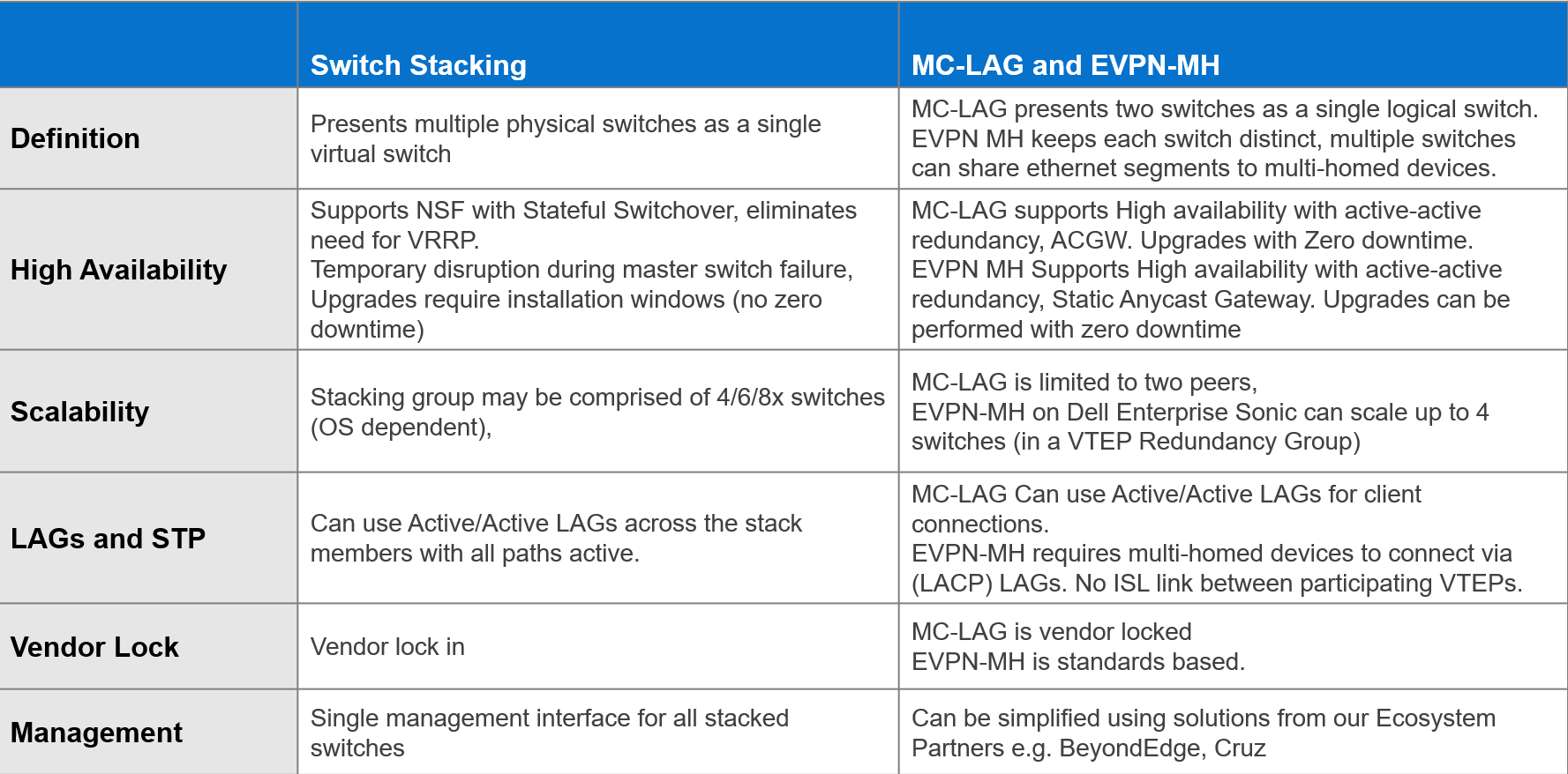
EVPN offers an upgrade to the legacy Layer 2 VPN technology. EVPN should be considered each time a new fabric is deployed, especially when virtualization is one of the workloads.
Dell Enterprise SONiC 4.2 offers even more simplicity into the adoption of EVPN in the data center.
Additional resources
Dell Enterprise SONiC 4.2.0 User Guide (log in required)

Data Center Interconnect (DCI) by Dell Enterprise SONiC
Tue, 28 Feb 2023 19:18:19 -0000
|Read Time: 0 minutes
Let’s talk about how Dell Enterprise SONiC is bringing Data Center Interconnect (DCI) into the mix with open source.
A data center is the beating heart of any IT enterprise environment. It used to be a sunk investment, providing little to no return. As the data center evolved into a positive asset that an enterprise could leverage, the ability to interconnect with other data centers became a critical capability. Today, the ubiquitous adoption of virtualization and application services availability is driving demand for integration in current data centers.
The interconnection of data centers is not new; enterprises use many different technologies to interconnect data centers. For example, VPLS or virtual private LAN service is an Ethernet based point to multipoint Layer 2 virtual private network that connects geographically dispersed data centers as if they are connected over a common Layer 2 connection.
Unfortunately, when these technologies were created, they were based on having a Multi-Protocol Label Switching (MPLS) backbone, so deploying them is often complex.
Ethernet Virtual Private Network (EVPN) DCI is all about deploying an overlay based on the familiarity of 802.1q VLANs, that is, stretching Layer 2 over a Layer 3 backbone.
In its first release, Enterprise SONiC Distribution by Dell Technologies supported single-site EVPN fabrics for single-site data centers. As Dell Enterprise SONiC becomes more popular, the fabrics built using Enterprise SONiC need to connect with each other by leveraging simple Layer 2 and Layer 3 technologies.
To achieve this, Dell introduced key EVPN VXLAN components that allow data center interconnectivity.
Let's get together and collaborate
With the proliferation and exponential data growth, the single site data center can no longer absorb or meet the data demands. Connecting multiple data centers to leverage their respective resources is key to the adoption of new applications, services, and overall new business income streams.
Figure 1 shows two typical single site data centers isolated from each other. In this case, the resources (such as storage and compute) reside within a single data center. This type of deployment presents unique challenges, including lack of integration, and potentially site redundancy.
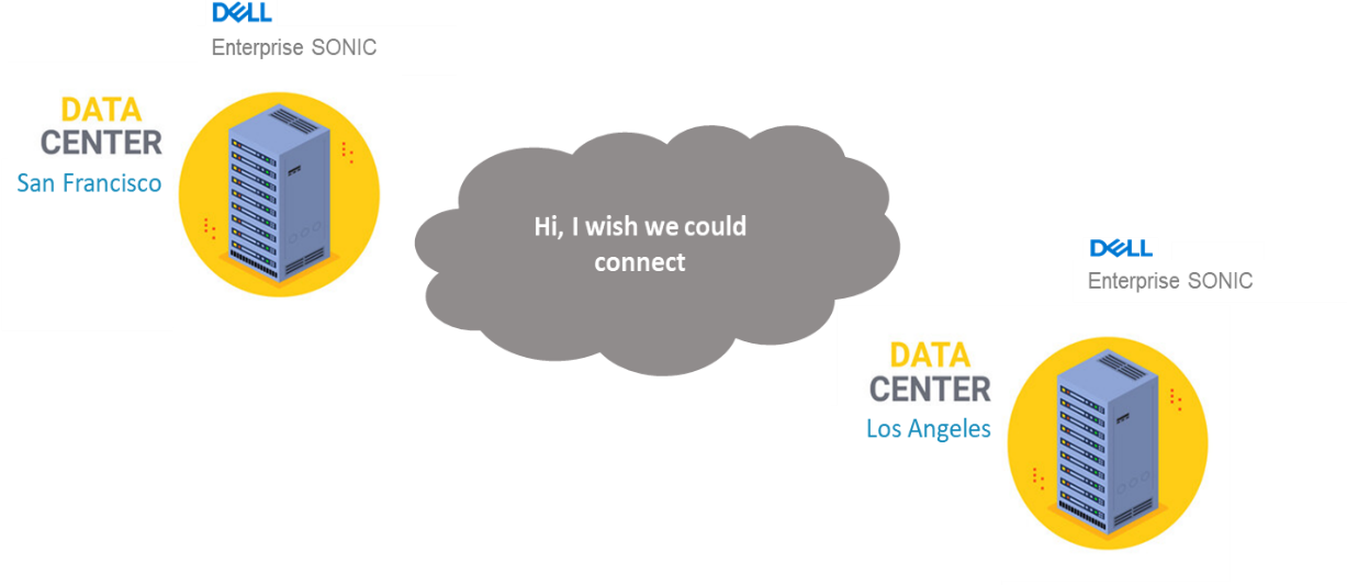 Figure 1 – Typical single site data centers collocated but isolated
Figure 2 shows several data centers interconnected over EVPN DCI. Dell Enterprise SONiC version 4.0 introduces the much-needed EVPN VXLAN software feature-set enhancement that allows for different geographically located data centers to interconnect.
This new feature allows multiple use cases such as:
- Workload cluster bring-up
- vSAN stretch cluster
- Efficient resource sharing
- Standards based fabric connectivity
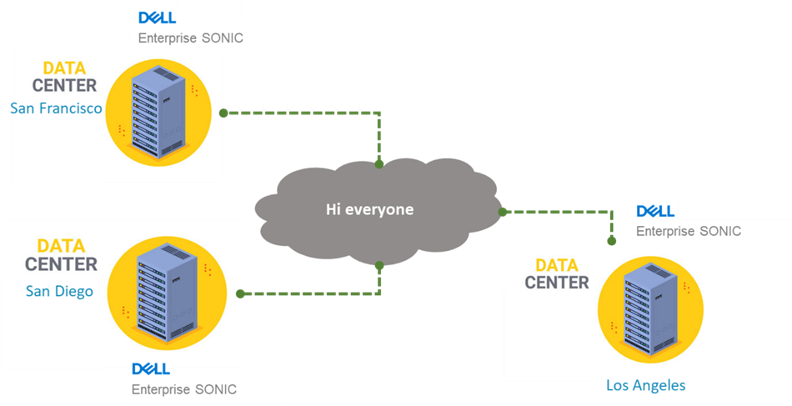 Figure 2 – Full mesh multisite data center connections
References
To learn more about Dell Enterprise SONiC Distribution and related solutions please see:
Enterprise SONiC Distribution by Dell Technologies
Enterprise SONiC Distribution Data Center Interconnect Guide
Enterprise SONiC Distribution User Guide
Note: Consult with your Dell sales engineer or representative if access to the Dell Enterprise SONiC User Guide is not available.