


Dell Technologies PowerEdge MX Platform: Backing Up and Restoring the MX Platform
An essential part of any data center disaster recovery plan is the ability to back up and restore the infrastructure. As a best practice, logs, server settings, routing information, and switch configurations should be backed up, with several copies secured in multiple locations.
The Dell Technologies PowerEdge MX Platform OME-M 1.40.00 release includes a significant new addition to the backup and restore feature: SmartFabric settings are now included.
This blog describes the full network backup and restore process, with emphasis on the SmartFabric settings and complete IOM startup.xml configuration.
Backing up the MX7000 chassis
In the following scenarios, you might need to restore the MX7000 chassis:
- The chassis was misconfigured
- The MX platform is unresponsive or malfunctioning
- Configurations were deleted due to disaster or human error
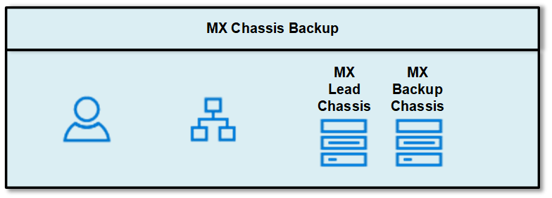
Note: If the MX chassis is in a MultiChassis Management (MCM) group, the backup will only be performed on the lead chassis. Member chassis do not need to be backed up because they inherit the configuration from the lead chassis.
MX Chassis, OME-M, and SmartFabric settings and configurations
MX platform backups include the following configurations and settings:
- Application settings
- Setup configuration
- Power configuration
- Chassis network configuration
- Local access configuration
- Location configuration
- Slot configuration
- OME Modular network settings
- User's settings
- Security settings
- Alert settings
OME-M 1.40.00 introduces the following:
- System configuration
- Templates
- Profiles
- Identity pools and VLANs
- Catalogs and baselines
- Alert policies
- SmartFabric
- MCM configuration
Back up the MX platform
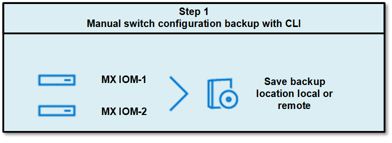
The OME-M Chassis Backup wizard includes chassis settings and configurations, but it does not include the I/O Modules (IOMs) configuration. Let’s get started by backing up the IOM configurations manually through the CLI.
Manual backup of IOM configuration provides a backup of the running configuration. The running configuration contains the current OS10 system configuration and consists of a series of OS10 commands in a text file that you can view and edit with a text editor. Copy the configuration file to a remote server or local directory as a backup or for viewing and editing.
- In the CLI, run the following command to manually save each IOM switch configuration:
OS10# copy running-configuration startup-configuration - Back up the startup file to the local directory or on external resources such as an TFTP server, an FTP server, or a USB drive.
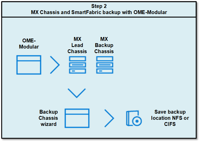
In the example below, the configuration is saved on a local directory of the switch by running the following CLI:OS10# copy config://startup.xml config://backup-3-22.xml - Access the MX lead chassis Overview page and click More Actions > Backup.
The Chassis Backup wizard is displayed.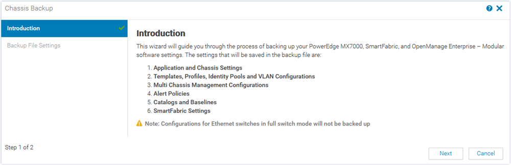
- On the Introduction page, review the settings that are included in the backup file and click Next.
The Backup File Settings page is displayed.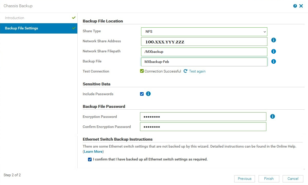
- In Backup File Location, select the Share Type where you want to store the chassis backup file.
The available options are CIFS and NFS.
In this example, NFS is selected. Therefore, the NFS server should be preconfigured and the network connection should be tested before starting the backup process. - Enter the Network Share Address and the Network Share FilePath name of the backup file after a forward slash. For example /MXbackup
The Network Share Address is the NFS server NIC IP. The Network Share FilePath must be predefined on the NFS server, the file path, or the folder where the backup file will be saved. - Enter a name for the Backup File.
In this example, MXbackup-Feb is entered. - (Optional) Select Test connection. If the MX chassis and NFS server are in the same network, you can skip this step.
- (Optional) To allow users to include passwords while backing up the chassis, select Sensitive Data.
For more information about sensitive data, see Chassis Backup and Restore. - In Backup File Password, enter a password in the Encryption Password and Confirm Encryption Password textboxes.
The backup file is encrypted and cannot be edited. Only authorized users can retrieve and restore the file on the chassis. Provide the password and secure it in a safe place.
Note: The password must be 8 to 32 characters long and must be a combination of an uppercase, a lowercase, a special character (+, &, ?, >, -, }, |, ., !, (, ', ,, _, [, ", @, #, ), *, ;, $, ], /, §, %, =, <, :, {, I) , and a number.
- In the Ethernet Switch Backup Instructions, select the check box to confirm that you have manually saved the Ethernet switch backup settings.
For more detailed information about all Ethernet switch CLI settings, see CLI commands not part of chassis backup.- When the MX7000 chassis is in SmartFabric mode, the backup process does not include some switch settings.
- In Full Switch mode, the chassis backup process does not include any switch settings.
- To start the backup, click Finish.
- (Optional) To view the progress of the backup operation:
- Click Monitor > Jobs.
- Select the appropriate job and click View Details.
Available information includes current task status, percentage complete, elapsed time, and much more.
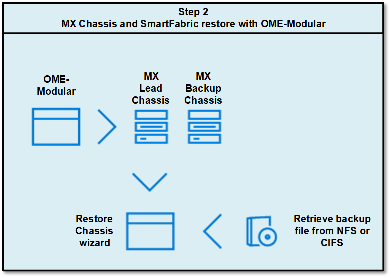
Restore the MX platform
This section describes the steps to restore an MX chassis and the IOM configuration.
You can use the OME-M GUI to restore the MX chassis working configuration with the backup file we created in the previous section.
The GUI doesn’t restore the IOM configuration, so you can manually restore the IOM configuration through the CLI.
Before you start the restore operation, make sure you have network access to the location where the backup file has been saved.

Restore the system
As a best practice, verify network connectivity to the location where the backup file has been saved.
You can restore the chassis through the OME-M GUI. The GUI doesn’t restore the IOM configuration, so the IOM configuration must be restored manually through the CLI.
- From the lead chassis, open the OME-M GUI and browse to Overview > More Actions > Restore.
The Introduction page displays.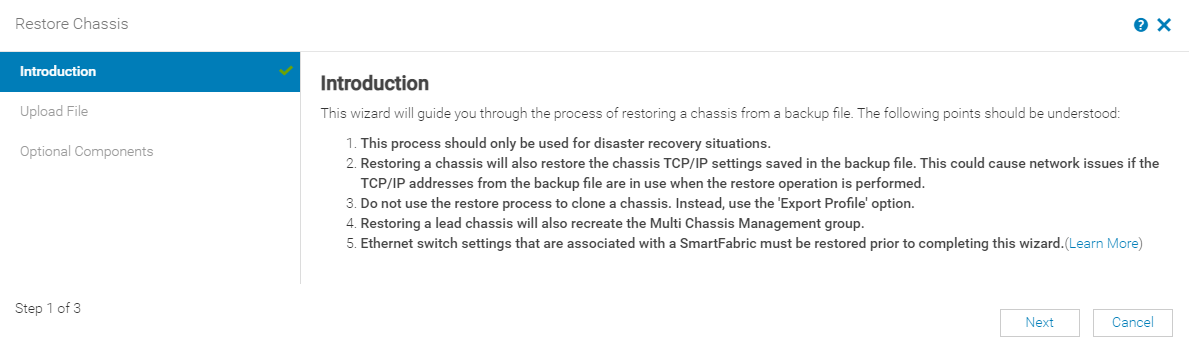
- Read the process and click the Learn More link in point 5 (shown in the figure above) to see more information about the Ethernet switch restore.
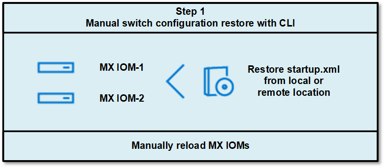
Note: Do not click Next. The Ethernet switch configuration must be manually restored before proceeding to the next step in the restore wizard. - Access the MX IOM CLI of each switch and restore the Ethernet Switch configuration.
The IOMs can be restored manually from the local directory on the switch or from external resources such as an TFTP server, an FTP server, or a USB drive. In this example, the IOMs manually restore through the CLI from the local directory on the switch.
In the CLI, run the following command:OS10# copy config://backup-3-22.xml config://startup.xmlOS10# reloadProceed to reboot the system? [confirm yes/no]:yesSystem configuration has been modified. Save? [yes/no]:noCaution: Reload the IOMs immediately after restoring the startup configuration, because the running configuration is automatically written to the startup.xml every 30 minutes. Reloading the IOM immediately after each startup configuration restore avoids the startup.xml being overwritten.
- After the IOMs are restored and reloaded successfully, resume the restore process in the OME-M GUI. Click Next on the Introduction page.
The Upload File page displays.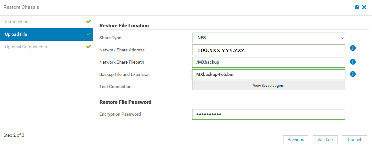
- Enter the restore file location details and enter the encryption password.
- In the Restore File section, enter the appropriate information.
Field
Input
Share Type
Select the share type where the configuration backup file is located.
In our example, since we selected the NFS server option for our backup, select NFS.
Network Share Address
Provide the NFS server NIC IP.
Network Share Filepath
Enter the same Network Share Filepath used for the backup file, including a forward slash: /MXbackup
Backup Filename
Type the Backup Filename with extension as shown in the figure above: MXbackup-Feb.bin.
- In the Restore File Password section, provide the same Encryption Password used during the backup process. The encryption password prevents unauthorized access.
- In the Restore File section, enter the appropriate information.
- To validate the chassis connectivity with the NFS server or location where backup file is saved, click Validate.
After the validation completes successfully, the Optional Components section is displayed.
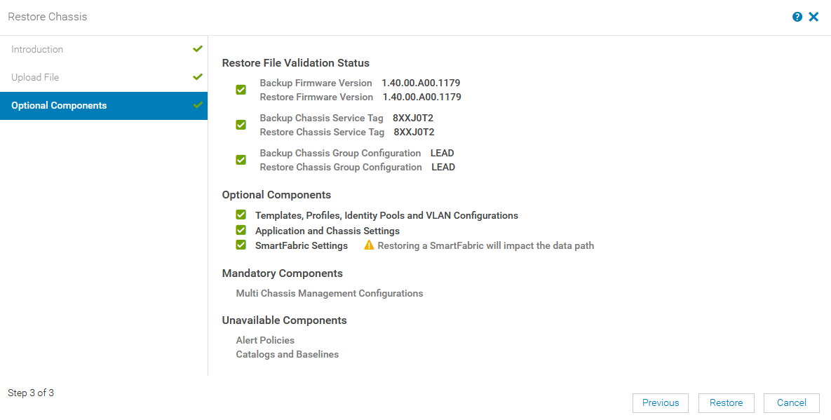
- (Optional) On the Optional components page, you can choose to restore files on the selected components.
The following table provides details about the available options:Component
Description
Restore File Validation Status
Displays the validation status of the restore files
- Backup and restore chassis firmware version
Note: The restore chassis firmware version must match the firmware version that was installed when the backup file was created. - Backup and restore chassis service tag information
- The role of the backup chassis and the restore chassis
Optional Components
Displays the components that you can select for the restore operation.
Mandatory Components
Displays mandatory components, if applicable.
A restoring chassis that is in the MCM group is a Mandatory Component. Mandatory components restore automatically in the restore process.
Unavailable Components
Displays all other components that were not backed up during the backup process and are therefore unavailable for the restore operation.
- Backup and restore chassis firmware version
- Click Restore to start the chassis restore process.
- (Optional) To view the progress of the restore operation:
- Click Monitor > Jobs.
- Select the appropriate job and click View Details.
Available information includes current task status, percentage complete, elapsed time, and much more.
Notes:
- The restore process may take several hours, depending on the network settings and configuration.
- Once the MCM lead chassis has been restored, set the backup lead manually by assigning a backup lead chassis.
Resources
Dell Technologies PowerEdge MX7000 Networking Deployment Guide
Dell Technologies OME-M for PowerEdge MX7000 Chassis User’s Guide
Dell Technologies PowerEdge MX7000 Networking Interactive Demos
Related Blog Posts

MX8116n Fabric Expander Modular (FEM) port mapping with external Fabric Switching Engine (FSE)
Fri, 14 Jul 2023 13:16:33 -0000
|Read Time: 0 minutes
The Dell Networking MX8116n FEM acts as an Ethernet repeater, taking signals from an attached compute sled and repeating those signals to the associated lane on the external QSFP56-DD connector. The MX8116n FEM includes two QSFP56-DD interfaces, with each interface providing up to four 100 Gbps connections to the chassis and eight internal 100 GbE server facing ports.
The Dell PowerSwitch Z9432F-ON fixed switch serves as the designated FSE of the MX platform and can support MX chassis deployed with 100 GbE or 25 GbE-based compute sleds. The switch comes equipped with 32 QSFP56-DD ports that provide uplinks, Virtual Link Trunking interconnect (VLTi), and fabric expansion connections.
The goal of this blog is to help you understand port-mapping information about MX8116n FEM, where the module is connected to NIC cards in compute sleds internally on one side and Fabric Switching Engine on the other side on external ports.
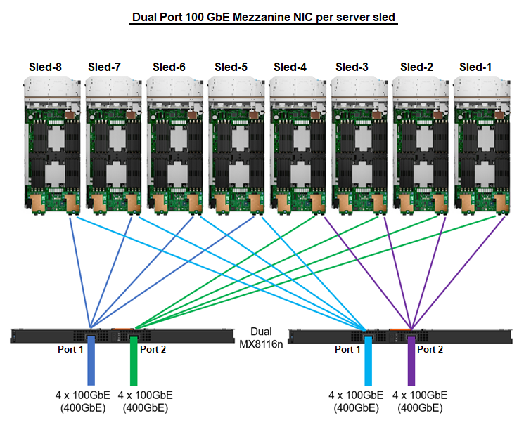
Figure 1. Port mapping of dual MX8116n FEM ports to NIC ports
Sled 1 through Sled 4 use Port 2 on the MX8116n, while Sled 5 through Sled 8 use Port 1.

Figure 2. MX8116n internal port mapping
The MX7000 chassis supports up to four MX8116n FEMs in Fabric A and Fabric B. Figure 3 shows one MX8116n FEM module that has two QSFP56-DD 400 GbE ports that can be split into 4x100 GbE to FSE facing ports and 8x100 GbE to facing internal sled NIC ports.
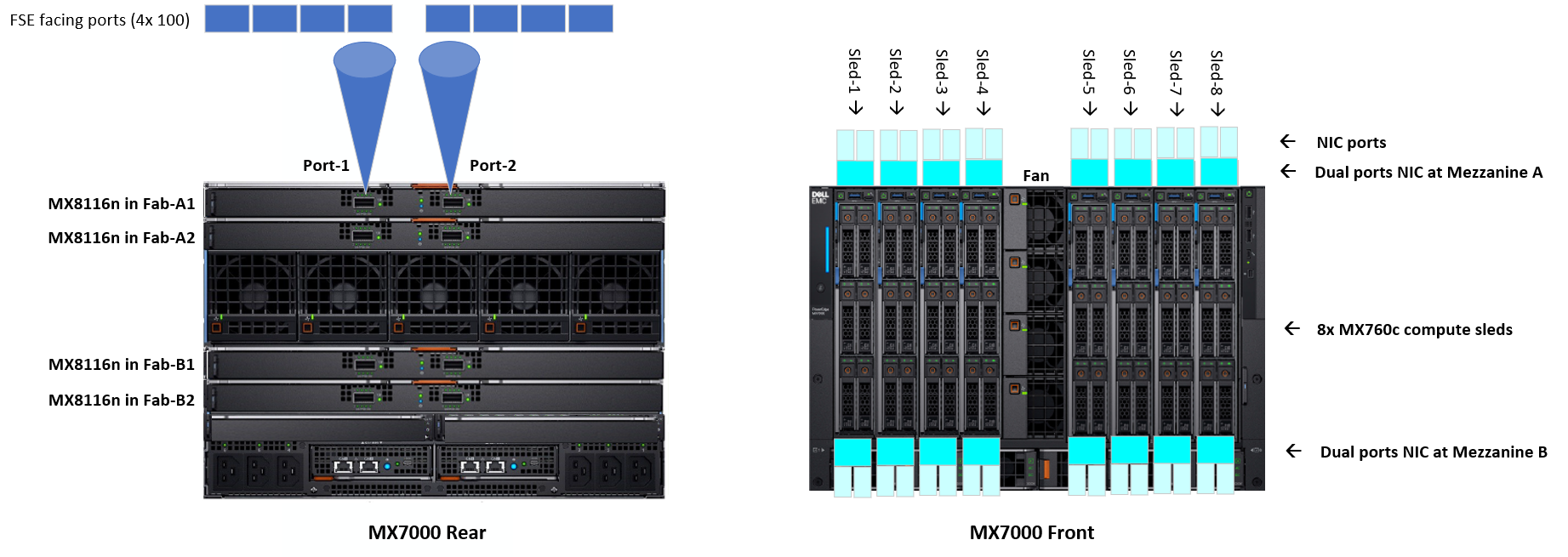
Figure 3. MX7000 chassis front and back physical view with IOMs and sleds port mapping
The MX8116n FEM can operate at 25 GbE and 100 GbE. The 25 GbE solution can support on both dual and quad port NICs, while the 100 GbE solution is supported on dual port NIC only. For the following examples in this blog, the PowerSwitch Z9432F-ON port mapping on 100 GbE dual port NIC using QSFP56-DD cables and 25 GbE dual port and quad port NICs using QSFP56-DD and QSFP28-DD.
The interfaces used on the Z9432F-ON are arbitrary. QSFP56-DD interfaces on the Z9432F-ON can be connected in any order.
Each port group in PowerSwitch Z9432F-ON contains two physical interfaces. The following examples shows the ports of the first port group 1/1/1 that contain interfaces 1/1/1-1/1/2 and the ports of the last port group 1/1/16 that contain interfaces 1/1/31-1/1/32. The port mode for each port interface can be configured in the port group configuration.
Compute sleds with 100 GbE dual port mezzanine cards
The following port group settings are required for 100 GbE dual port mezzanine cards for the Z9432F-ON:
port-group 1/1/1
profile unrestricted
port 1/1/1 mode Eth 100g-4x
port 1/1/2 mode Eth 100g-4x
port-group 1/1/16
profile unrestricted
port 1/1/31 mode Eth 100g-4x
port 1/1/32 mode Eth 100g-4x
Once the port modes are configured and the connections are made, the MX8116n ports auto negotiate to match the port operating mode of the Z9432F-ON interfaces. The internal servers facing ports of the MX8116n auto-negotiate with the mezzanine card port speed of 100 GbE.
Figure 4 shows the interface numbering for each sled and corresponding MX8116n port when using a QSFP56DD based optic or cable:
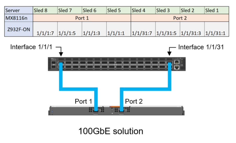
Figure 4. Z9432F-ON port mapping for 100 GbE solution
Compute sleds with 25 GbE quad port NIC using QSFP56-DD
The following port group settings are required for 25 GbE quad port NIC using QSFP56-DD on the Z9432F-ON:
- For the required 25g-8x port mode operation, the profile must first be set to restricted. This restriction means that the second port interface in the port group can only operate in a restricted mode.
- The restriction on the second port means that it must operate in a 1x mode, making the even ports unsuitable for connections to the MX8116n. Therefore, only the odd ports can be used for connections to the MX8116n.
port-group 1/1/1
profile restricted
port 1/1/1 mode Eth 25g-8x
port 1/1/2 mode Eth 400g-1x
port-group 1/1/16
profile restricted
port 1/1/31 mode Eth 25g-8x
port 1/1/32 mode Eth 400g-1x
Figure 5 shows the interface numbering for each sled and corresponding MX8116n port when using a QSFP56DD based optic or cable:
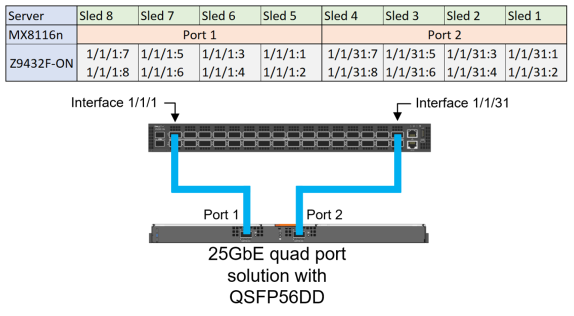
Figure 5. Z9432F-ON Port mapping for 25 GbE quad port solution for QSFP56DD based optics and cables
Compute sleds with 25 GbE quad port NIC using QSFP28-DD
The 25 GbE quad port NIC solution can use QSF28-DD based optics and cables. The following configuration shows the final state required for 25 GbE quad port NICs:
port-group 1/1/1
profile restricted
port 1/1/1 mode Eth 25g-8x
port 1/1/2 mode Eth 400g-1x
port-group 1/1/16
profile restricted
port 1/1/31 mode Eth 25g-8x
port 1/1/32 mode Eth 400g-1x
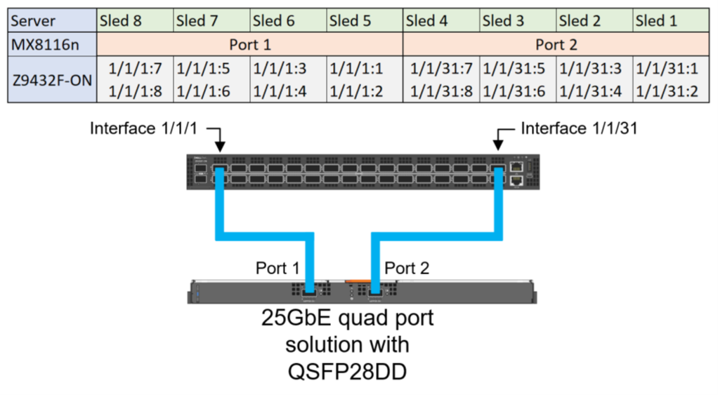
Figure 6. Z9432F-ON Port mapping for 25 GbE quad port solution with QSFP28-DD based optics and cables
Compute sleds with 25 GbE dual port NIC using QSFP56-DD
For the required 25g-4x port mode operation, the profile should stay in the default unrestricted setting. Unlike quad port deployments, dual port deployments can use both even and odd ports on the Z9432F-ON.
port-group 1/1/1
profile unrestricted
port 1/1/1 mode Eth 25g-8x
port 1/1/2 mode Eth 400g-1x
port-group 1/1/16
profile unrestricted
port 1/1/31 mode Eth 25g-8x
port 1/1/32 mode Eth 400g-1x
Figure 7 shows the interface numbering for each sled and corresponding MX8116n port when using a QSFP56DD based optic or cable:
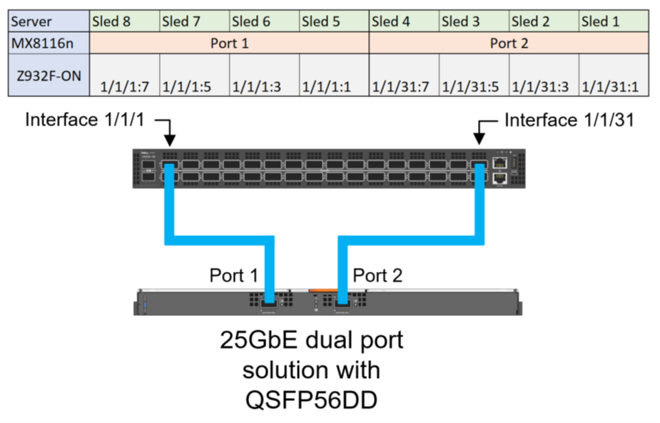
Figure 7. Z9432F-ON Port mapping for 25 GbE dual port solution for QSFP56DD based optic or cable
Compute sleds with 25 GbE dual port NIC using QSFP28-DD
The following configuration shows the final state required for 25 GbE dual port mezzanine cards, the profile should stay in the default unrestricted setting:
port-group 1/1/1
profile unrestricted
port 1/1/1 mode Eth 25g-4x
port 1/1/2 mode Eth 400g-1x
port-group 1/1/16
profile unrestricted
port 1/1/31 mode Eth 25g-4x
port 1/1/32 mode Eth 400g-1x
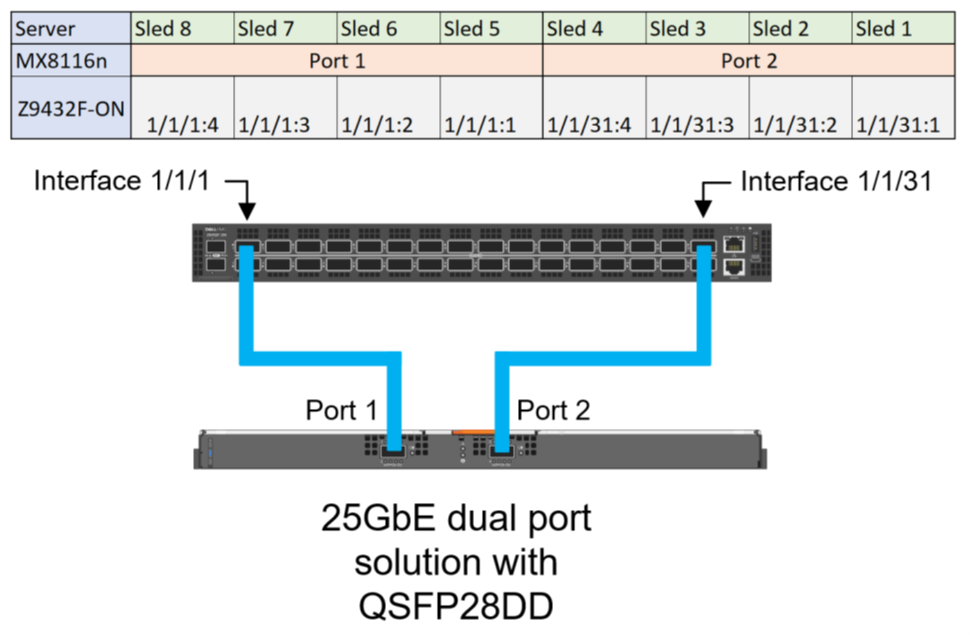
Figure 8. Z9432F-ON Port mapping for 25 GbE dual port solution with QSFP28-DD based optics and cables
References
Dell PowerEdge MX Networking Deployment Guide
Dell Technologies PowerEdge MX 100 GbE Solution with external FSE blog
Dell PowerEdge MX7000 Chassis User Guide

Dell Technologies PowerEdge MX 100 GbE solution with external Fabric Switching Engine
Mon, 26 Jun 2023 20:31:38 -0000
|Read Time: 0 minutes
The Dell PowerEdge MX platform is advancing its position as the leading high-performance data center infrastructure by introducing a 100 GbE networking solution. This evolved networking architecture not only provides the benefit of 100 GbE speed but also increases the number of MX7000 chassis within a Scalable Fabric. The 100 GbE networking solution brings a new type of architecture, starting with an external Fabric Switching Engine (FSE).
PowerEdge MX 100 GbE solution design example
The diagram shows only one connection on each MX8116n for simplicity. See the port-mapping section in the networking deployment guide here.
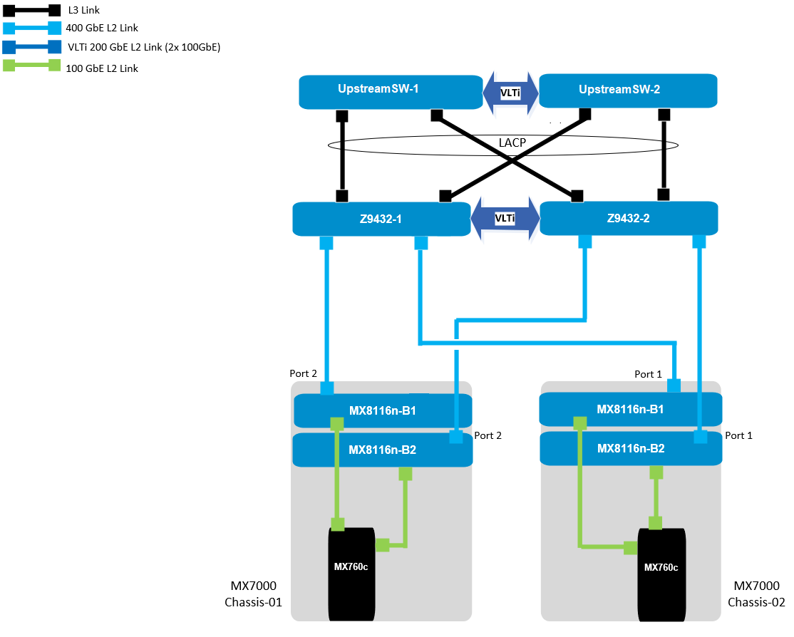
Figure 1. 100 GbE solution example topology
Components for 100 GbE networking solution
The key hardware components for 100 GbE operation within the MX Platform are described below with a minimal description.
Dell Networking MX8116n Fabric Expander Module
The MX8116n FEM includes two QSFP56-DD interfaces, with each interface providing up to 4x 100Gbps connections to the chassis, 8x 100 GbE internal server-facing ports for 100 GbE NICs, and 16x 25 GbE for 25 GbE NICs.
The MX7000 chassis supports up to four MX8116n FEMs in Fabric A and Fabric B.
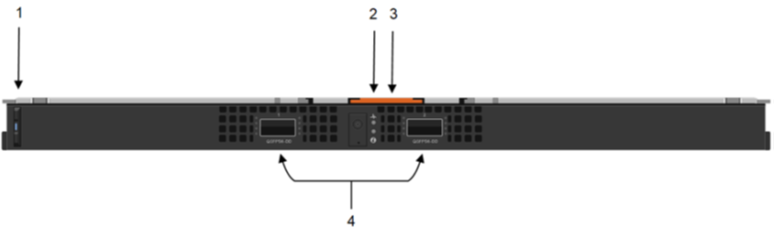
Figure 2. MX8116n FEM
The following MX8116n FEM components are labeled in the preceding figure:
- Express service tag
- Power and indicator LEDs
- Module insertion and removal latch
- Two QSFP56-DD fabric expander ports
Dell PowerEdge MX760c compute sled
- The MX760c is ideal for dense virtualization environments and can serve as a foundation for collaborative workloads.
- Businesses can install up to eight MX760c sleds in a single MX7000 chassis and combine them with compute sleds from different generations.
- Single or dual CPU (up to 56 cores per processor/socket with four x UPI @ 24 GT/s) and 32x DIMM slots DDR5 with eight memory channels.
- 8x E3.S NVMe (Gen5 x4) or 6 x 2.5" SAS/SATA SSDs or 6 x NVMe (Gen4) SSDs and iDRAC9 with lifecycle controller.
Note: The 100 GbE Dual Port Mezzanine card is also available on the MX750c.
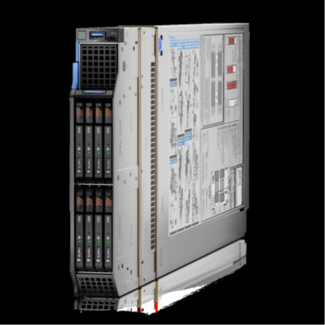
Figure 3. Dell PowerEdge MX760c sled with eight E3.s SSD drives
Dell PowerSwitch Z9432F-ON external Fabric Switching Engine
The Z9432F-ON provides state-of-the-art, high-density 100/400 GbE ports, and a broad range of functionality to meet the growing demands of modern data center environments. Compact and offers an industry-leading density of 32 ports of 400 GbE in QSFP56-DD, 128 ports of 100, or up to 144 ports of 10/25/50 (through breakout) in a 1RU design. Up to 25.6 Tbps non-blocking (full duplex), switching fabric delivers line-rate performance under full load.L2 multipath support using Virtual Link Trunking (VLT) and Routed VLT support. Scalable L2 and L3 Ethernet switching with QoS and a full complement of standards-based IPv4 and IPv6 features, including OSPF and BGP routing support.

Figure 4. Dell PowerSwitch Z9432F-ON
Note: Mixed dual port 100 GbE and quad port 25 GbE mezzanine cards connecting to the same MX8116n are not a supported configuration.
100 GbE deployment options
There are four deployment options for the 100 GbE solution, and every option requires servers with a dual port 100 GbE mezzanine card. You can install the mezzanine card in either mezzanine slot A, B, or both. When you use the Broadcom 575 KR dual port 100 GbE mezzanine card, you should set the Z9432F-ON port-group to unrestricted mode and configure the port mode for 100g-4x.
PowerSwitch CLI example:
port-group 1/1/1
profile unrestricted
port 1/1/1 mode Eth 100g-4x
port 1/1/2 mode Eth 100g-4x
Note: The 100 GbE solution deployment, 14 maximum numbers of chassis are supported in single fabric, and 7 maximum numbers of chassis are supported in dual fabric using the same pair of FSE solution.
Single fabric
In a single fabric deployment, two MX8116n can be installed either in Fabric A or Fabric B, and the corresponding slot of the sled in slot-A or slot-B can have the 100 GbE mezzanine card installed.
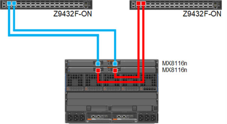
Figure 5. 100 GbE Single Fabric
Dual fabric combined fabrics
In this option, four MX8116n (2x in Fabric A and 2x in Fabric B) can be installed and combined to connect Z9432F-ON external FSE.
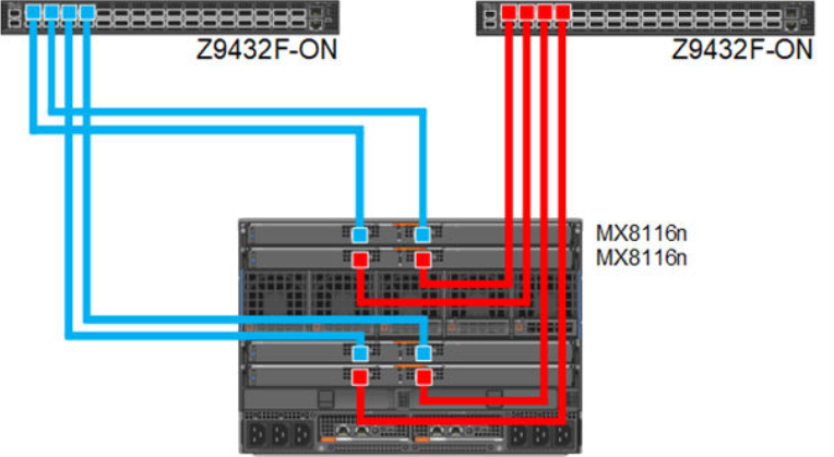
Figure 6. 100 GbE Dual Fabric combined Fabrics
Dual fabric separate fabrics
In this option four, MX8116n (2x in Fabric A and 2x in Fabric B) can be installed and connected to two different networks. In this case, the MX760c server module has two mezzanine cards, with each card connected to a separate network.
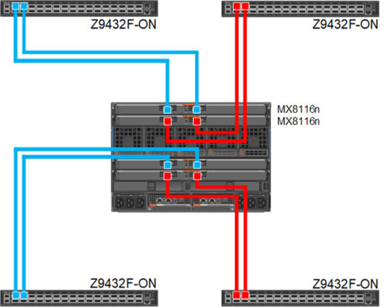
Figure 7. 100 GbE Dual Fabric separate Fabrics
Dual fabric, single MX8116n in each fabric, separate fabrics
In this option two, MX8116n (1x in Fabric A and 1x in Fabric B) can be installed and connected to two different networks. In this case, the MX760c server module has two mezzanine cards, each connected to a separate network.
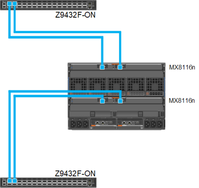
Figure 8. 100 GbE Dual Fabric single FEM in separate Fabrics
References
Dell PowerEdge Networking Deployment Guide
A chapter about 100 GbE solution with external Fabric Switching Engine