
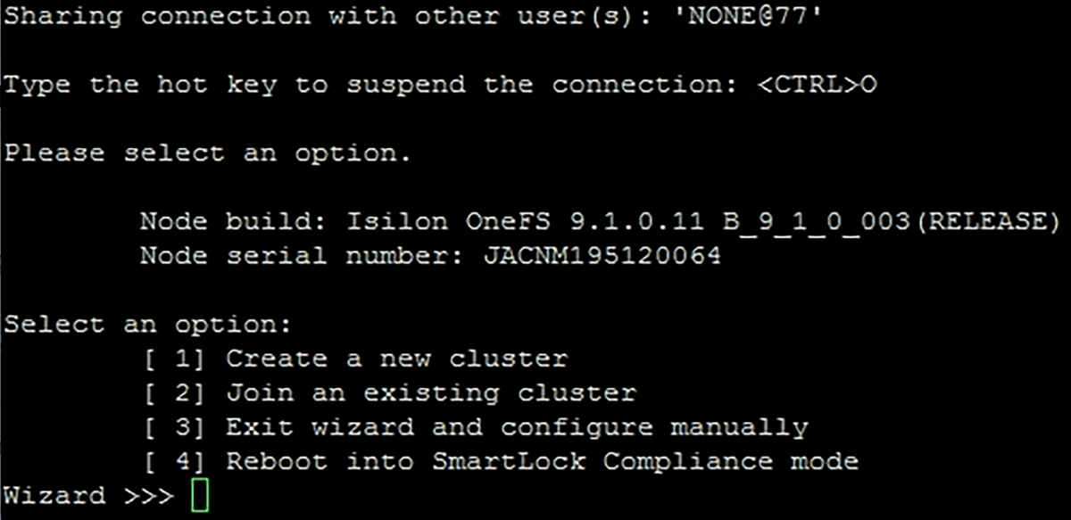
The first step in configuring the Isilon array is building the cluster. Once the array is powered on, a serial connection can be made to each node. Connect to the first node and use the cluster creation wizard to build the cluster. The following table shows the values that are used in this example. If any additional information is needed on the setup and configuration of the Isilon Array cluster, refer to the Isilon Generation 6 Installation Guide.
The following configurations are made in this section:
- Cluster name is defined
- IP ranges are assigned for the back-end network.
- Configuration of the management 1 GbE ext-1 connections are configured in the next section with the OneFS UI.
| Parameter | Value |
| Option | [1] Create a new cluster |
| Configure root and admin passwords | ******* |
| Configure name | Cluster-01 |
| Cluster encoding | [8] UTF-8 |
| Interface int-a netmask | 255.255.255.0 |
| Interface int-a IP range | 10.10.10.1-253 |
| Interface int-b netmask | 255.255.255.0 |
| Interface int-b IP range | 10.10.20.1-253 |
| Failover IP range | 10.10.30.1-253 |
| Interface mgmt.-1 netmask | 255.255.255.0 |
| MTU | 1500 |
| Interface mgmt.-1 IP pool | 100.67.108.181-188 |
| Mgmt. default gateway | 100.67.108.254 |
| SmartConnect Zone name | mgmtzone1 |
| SmartConnect service IP | 100.67.108.189 |
| DNS Server for L2 uplinks | 172.18.11.50 |
| DNS Server for L3 uplinks | 172.19.11.50 |
| Search domain | Dell.local |
| Cluster date and time | Default |
| Cluster join mode | Default |
| Commit changes | Yes |
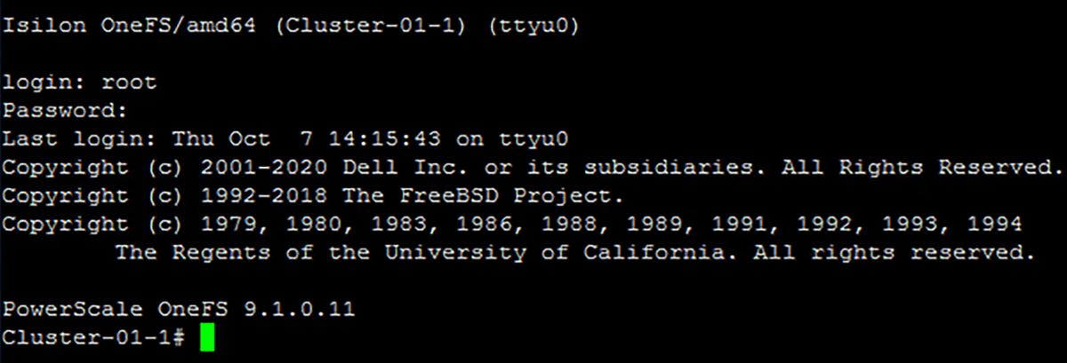
When the first node is configured, and the cluster has been created, the other nodes can then be added into the cluster. All nodes can discover the cluster over the back-end network. The assorted options for back-end networking and Isilon are not covered in this document. For more information about the back-end network, refer to Isilon documentation.