Home > Networking Solutions > Converged and Hyperconverged Solutions > VxRail Networking Solutions > Guides > VMware Cloud Foundation on VxRail Multirack Deployment Using BGP EVPN - Part 2 of 2 > Leaf-spine underlay
Leaf-spine underlay
-
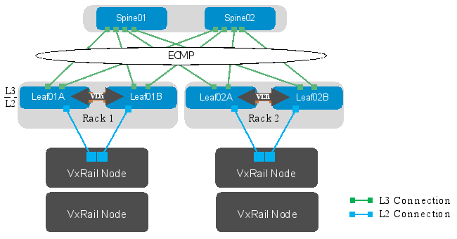
In a Layer 3 leaf-spine network, the traffic between leaf switches and spine switches are routed. Equal cost multipath routing (ECMP) is used to load balance traffic across the Layer 3 connections. BGP is used to exchange routes. The Layer 3/Layer 2 (L3/L2) boundary is at the leaf switches.
Two leaf switches are configured as Virtual Link Trunking (VLT) peers at the top of each rack. VLT allows all connections to be active while also providing fault tolerance. As administrators add racks to the data center, two leaf switches configured for VLT are added to each new rack. Connections within racks from hosts to leaf switches are Layer 2, and each host is connected using a VLT port-channel.
In this example, two Z9264F-ON switches are used as spines, and four S5248F-ON switches are used as leaf switches in Rack 1 and Rack 2.

Figure 11. Leaf-spine underlay network
Note: Using a leaf-spine network in the data center is considered a best practice. With Z9264F-ON switches as spines and two leaf switches per rack, this topology scales to 32 racks. For more leaf-spine network information, see Dell EMC Networking Layer 3 Leaf-Spine Deployment and Best Practices with OS10. There are some BGP configuration differences in this guide to enable the BGP EVPN VXLAN feature.
BGP ASNs and router IDs
Figure 12 shows the autonomous system numbers (ASNs) and router IDs used for the leaf and spine switches in this guide. Spine switches share a common ASN, and each pair of leaf switches shares a common ASN.
ASNs should follow a logical pattern for ease of administration and allow for growth as switches are added. Using private ASNs in the data center is the best practice. Private, 2-byte ASNs range from 64512 through 65534.
In this example, 65100 is used on both switches at the spine layer. Leaf switches use the next available ASNs, 65101, for example, and the last digit is used to identify the leaf pair. Extra spine switches would be assigned the existing ASN for the spine layer, 65100. Extra leaf switches would be added in pairs with the next pair assigned an ASN of 65103.
The IP addresses shown are loopback addresses that are used as BGP router IDs. Loopback addresses should follow a logical pattern to make it easier to manage and allow for growth. In this example, the 10.0.0.0/16 IP address space is used. The third octet in the address represents the layer, “1” for the spine layer and “2” for the leaf layer, and the fourth octet is the counter for the appropriate layer

Figure 12. BGP ASNs and router IDs
Point-to-point IP networks
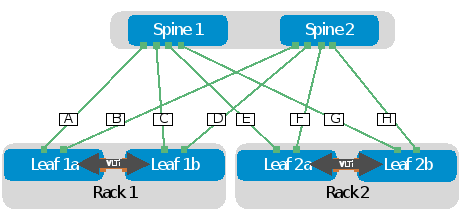
Establishing a logical, scalable IP address scheme is important before deploying a leaf-spine topology. The point-to-point links used in this deployment are labeled A-H in Figure 13.

Figure 13. Point-to-point networks
Each link is a separate, point-to-point IP network. Table 1 details the links labeled in Figure 13. The IP addresses in the table are used in the switch configuration examples.
Table 1. Point-to-point network IP addresses
Link
label
Source switch
Source IP address
Destination switch
Destination IP address
Network
A
Spine 1
192.168.1.0
Leaf 1a
192.168.1.1
192.168.1.0/31
B
Spine 2
192.168.2.0
Leaf 1a
192.168.2.1
192.168.2.0/31
C
Spine 1
192.168.1.2
Leaf 1b
192.168.1.3
192.168.1.2/31
D
Spine 2
192.168.2.2
Leaf 1b
192.168.2.3
192.168.2.2/31
E
Spine 1
192.168.1.4
Leaf 2a
192.168.1.5
192.168.1.4/31
F
Spine 2
192.168.2.4
Leaf 2a
192.168.2.5
192.168.2.4/31
G
Spine 1
192.168.1.6
Leaf 2b
192.168.1.7
192.168.1.6/31
H
Spine 2
192.168.2.6
Leaf 2b
192.168.2.7
192.168.2.6/31
Note: As with all examples in this guide, any valid IP address scheme can be used. The earlier example point-to-point addresses use a 31-bit mask to save address space. This is optional and covered in RFC 3021.
