
Reprotection with SRDF/Non-Star
Reprotection with SRDF/Non-Star
-
The SRDF SRA fully supports reprotect for all Concurrent SRDF configurations and the following Cascaded SRDF configurations:
- First hop synchronous, second hop asynchronous with recovery to the synchronous site.
- First hop active, second hop asynchronous with recovery to the active site.
- First hop active, second hop asynchronous with recovery to the asynchronous site.
- First hop synchronous, second hop adaptive copy disk with recovery to the synchronous site.
- First hop asynchronous, second hop adaptive copy disk with recovery to the asynchronous site.
Note: A configuration where the first hop is synchronous and the second hop is asynchronous and the recovery site is the tertiary/asynchronous site, reprotection and failback is NOT supported from within SRM. Manual recovery is required, please refer to section Manual Reprotection/Failback of Cascaded SRDF after recovery to tertiary site for instructions.
Note: Reprotect workflow is not supported for SRDF/Metro 3-site, failover to ASYNC site or MetroDR. Reprotect requires manual steps on the array and a likely rebuilding of the SRM protection groups and recovery plan. These steps are beyond the scope of this document.
After a recovery plan has run, there are often cases where the environment must continue to be protected against failure to ensure its resilience and to meet objectives for disaster recovery. Site Recovery Manager offers “reprotection” which is an extension to recovery plan management that enables the environment at the recovery site to establish replication and protection of the environment back to the original protected site. This behavior allows users to recover the environment quickly and easily back to the original site if necessary.
It is important to note that a completely unassisted reprotection by VMware Site Recovery Manager may not always be possible depending on the circumstances and results of the preceding recovery operation. Recovery plans executed in “Planned Migration” mode are the likeliest candidates for a subsequent successful automated reprotection by SRM. Exceptions to this occur if certain failures or changes have occurred between the time the recovery plan was run and the reprotection operation was initiated. Those situations may cause the reprotection to fail. Similarly, if a recovery plan was executed in “Disaster Recovery” mode any persisting failures may cause a partial or complete failure of a reprotection of a recovery plan.
Note: If the advanced option, ReverseReplicationDuringRecovery is enabled the recovery site SRA will perform all reprotect operations relating to SRDF reconfiguration during the recovery process and reprotect will therefore only perform recovery plan/protection group swaps.
These different situations are discussed in the subsequent sections. Note that these sections cover both Concurrent SRDF/Non-Star and Cascaded SRDF/Non-Star configurations.
Reprotect after Planned Migration
The scenario that will most likely lead to a successful reprotection is after a planned migration. In the case of a planned migration there are no failures in either the storage or compute environment that preceded the recovery operation. No failures during a migration typically means that the state of the configuration is supported and therefore reversing recovery plans/protections groups as well as swapping and establishing replication in the reverse direction is possible.
Reprotect is only available for a recovery plan after a recovery operation has successfully occurred, which is indicated by the recovery plan being in the “Recovery Complete” state. A reprotect can be executed by selecting the appropriate recovery plan and selecting the “Reprotect” link as shown in Figure 174.
Figure 174. Executing a reprotect operation in VMware vCenter SRM
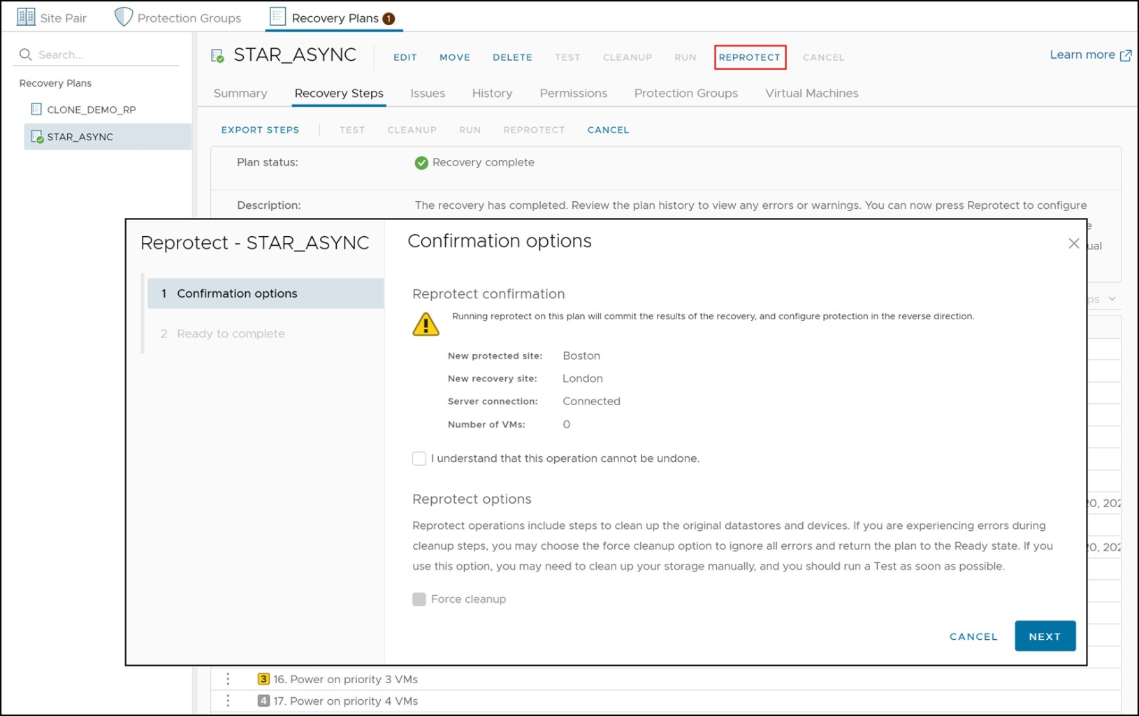
The reprotect operation does the following things:
- Reverses protection groups. The protection groups are deleted on the original protection SRM server and are recreated on the original recovery SRM server. The inventory mappings are configured (assuming the user has pre-configured them in SRM on the recovery site) and the necessary “shadow” or “placeholder” VMs are created and registered on the newly designated recovery SRM server[53].
- Reverses recovery plan. The failed-over recovery plan is deleted on the original recovery SRM server and recreated with the newly reversed protection group.
- Swaps personality of RDF devices. The SRDF SRA performs an RDF swap on the target RDF pairs which enables replication to be established back to the original site. R1 devices will become R2 devices and R2 devices will become R1 devices.
- Re-establishes replication. After the RDF swap, the SRDF SRA incrementally re-establishes replication between the RDF pairs, but in the opposite direction from what it was before the failover/migration. For 3-site configurations this often requires a reconfiguration between concurrent or cascaded.
The status of the devices after a migration, but before a reprotect operation, can be seen in Figure 175. The top portion of the figure shows the RDF state in Unisphere for VMAX of the device group containing the devices in the failed over protection group. Since the protection group was just failed over using the planned migration mode the RDF pair state is “Failed Over”. In the bottom half of the figure, the Dell VSI shows that the devices on the recovery site are still of type RDF2 indicating that an RDF swap has not yet occurred.
Figure 175. Device status before reprotect operation
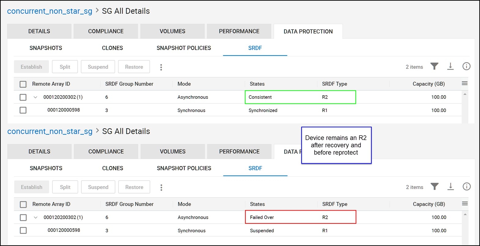
Figure 176 shows the steps involved in a reprotect operation.
Figure 176. Reprotect operation steps
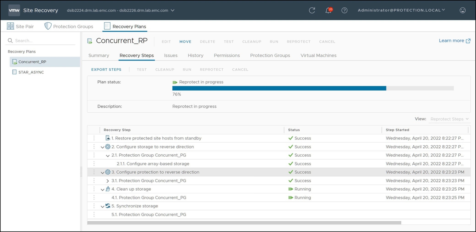
Step 1 of the reprotect operation (as shown in Figure 176) causes the SRA to issue an RDF personality swap and establish the replication in the reverse direction.
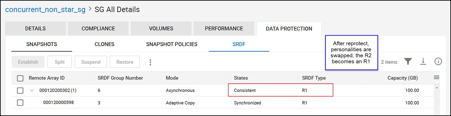
Figure 177 shows the same information as Figure 175, except instead it shows the device status after reprotection. The recovery site devices are now of type RDF1 and the RDF pair state will be either “SyncInProg”, “Synchronized” or “Consistent”. It can also be noted in comparing the previously mentioned two figures that the device groups types have swapped as well (between RDF1 and RDF2).
Figure 177. Device status after reprotect operation
When a Concurrent SRDF configuration is reprotected it will always be converted into a Cascaded configuration. Furthermore, in many cases it will not maintain the exact same protection scheme (in other words, the same mixture of Synchronous/Asynchronous/Adaptive Copy) that the device was originally configured with due to the changes from Concurrent to Cascaded. The following table (Table 31) shows all of the supported Concurrent configurations (prior to recovery) and their state after reprotection.
Table 30. Reprotection states of Concurrent SRDF
Initial state of R11 to R2 (1st mirror)
Initial state of R11 to R2 (2nd mirror)
After Reprotect R1 to R21
After Reprotect R21 to R2
Recovery to Asynchronous site enabled?
Synchronous
Asynchronous
Synchronous
Asynchronous
No
Synchronous
Asynchronous
Adaptive Copy Disk
Asynchronous
Yes
Synchronous
Adaptive Copy Disk
Synchronous
Adaptive Copy Disk
No
Synchronous
Adaptive Copy Write Pending
Synchronous
Adaptive Copy Disk
No
Synchronous
Synchronous
Synchronous
Adaptive Copy Disk
No
Asynchronous
Asynchronous
Asynchronous
Adaptive Copy Disk
Yes
Asynchronous
Adaptive Copy Disk
Asynchronous
Adaptive Copy Disk
Yes
Asynchronous
Adaptive Copy Write Pending
Asynchronous
Adaptive Copy Disk
Yes
Note: The SRA will never allow Adaptive Copy Write Pending mode to be a final state after reprotect. The SRA will always set Disk mode. This is because Concurrent SRDF using Adaptive Copy Write Pending mode in the second hop is not supported for recovery by Solutions Enabler or the SRA.
When a Cascaded SRDF configuration is reprotected it will always be converted into a Concurrent configuration. Furthermore, in many cases it will not maintain the exact same protection scheme (in other words, the same mixture of Synchronous/Asynchronous/Adaptive Copy) that the device was originally configured with due to the changes from Concurrent to Cascaded. The following table (Table 32.) shows all of the supported Concurrent configurations (prior to recovery) and their state after reprotection.
Table 31. Reprotection states of Cascaded SRDF
Initial state of R1 to R21 (1st hop)
Initial state of R21 to R2 (2nd hop)
After Reprotect R1 to R2 (1st mirror)
After Reprotect R1 to R2 (2nd mirror)
Recovery to Asynchronous site enabled?
Synchronous
Asynchronous
Synchronous
Asynchronous
No
Synchronous
Adaptive Copy Disk
Synchronous
Adaptive Copy Disk
No
Asynchronous
Adaptive Copy Disk
Asynchronous
Adaptive Copy Disk
Yes
Reprotect after a temporary failure
The previous section describes the best possible scenario for a smooth reprotection because it follows a planned migration where no errors are encountered. For recovery plans failed over in disaster recovery mode, this may not be the case.
Disaster recovery mode allows for failures ranging from the very small to a full site failure of the protection datacenter. If these failures are temporary and recoverable a fully-successful reprotection may be possible once those failures have been rectified. In this case, a reprotection will behave similar to the scenario described in the previous section. If a reprotection is run before the failures are corrected or certain failures cannot be fully recovered, an incomplete reprotection operation will occur. This section describes this scenario.
For reprotect to be available, the following steps must first occur:
- A recovery must be executed with all steps finishing successfully. If there were any errors during the recovery, the user needs to resolve the issues that caused the errors and then rerun the recovery.
- The original site should be available and SRM servers at both sites should be in a connected state. If the original site cannot be restored (for example, if a physical catastrophe destroys the original site) automated reprotection cannot be run and manual recreation will be required if and when the original protected site is rebuilt.
If the protected site SRM server was disconnected during failover and is reconnected later, SRM will want to retry certain recovery operations before allowing reprotect. This typically occurs if the recovery plan was not able to connect to the protected side vCenter server and power down the virtual machines due to network connectivity issues. If network connectivity is restored after the recovery plan was failed over, SRM will detect this situation and require the recovery plan to be re-run in order to power those VMs down.
A reprotection operation will fail if it encounters any errors the first time it runs. If this is the case, the reprotect must be run a second time but with the “Force cleanup” option selected as in Figure 178.
Figure 178. Forcing a reprotect operation
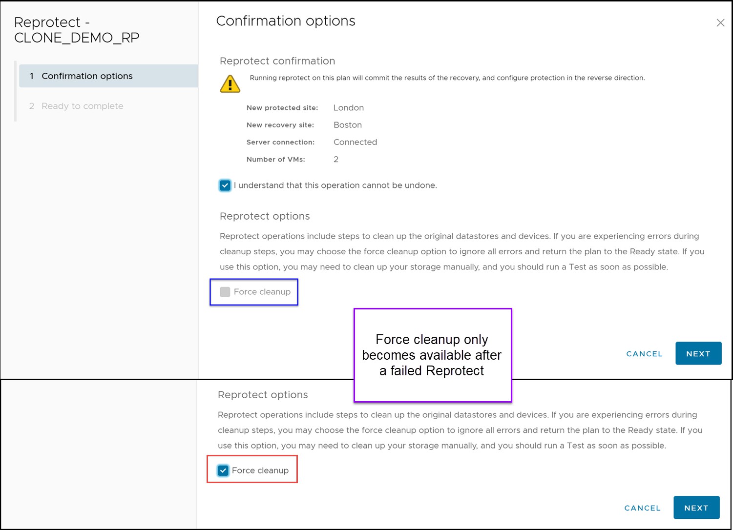
Once the force option is selected, any errors will be acknowledged and reported but ignored. This will allow the reprotect operation to continue even if the operation has experienced errors. It will attempt all of the typical steps and complete whichever ones are possible.
Therefore, in certain situations, the SRDF replication may not be properly reversed even though the recovery plan and protection group(s) were. If the “Configure Storage to Reverse Direction” step fails, manual user intervention with Unisphere for PowerMax or Solutions Enabler CLI may be required to complete the process. The user should ensure that:
- An RDF swap has occurred by ensuring the replicated target/source devices have changed personalities
- Replication has been re-established and is in an appropriate and supported SRDF replication mode
In the case of a temporary storage failure or replication partition, it is likely that manual intervention will be required prior to executing a reprotect operation. In this situation the R1 devices may not have been unmounted and write-disabled properly so invalid tracks may appear on the R1. When there are invalid tracks on both sites an RDF resume cannot be attempted and a reprotect operation will fail.
Therefore, a storage administrator must decide which invalid tracks must be cleared and then clear them from the appropriate devices. Once this has been done a reprotect may proceed. A message such as the one below will be reported when there are conflicting invalid tracks in the SRDF SRA log:
[ERROR]: Failed to perform RDF operation [RESUME
-FORCE] on CG [RDFConc], Symm [000195701248].
[ERROR]: [Solutions Enabler_C_RDF_CONF_INV_TRACKS : Cannot proceed because conflicting invalid tracks were found in the device group]
The typical method for clearing these invalids is to perform a manual RDF swap and then an establish operation instead of a resume.
Reprotect after a failover due to unrecoverable failure
In extreme circumstances, the storage and/or the compute environment may be rendered completely unrecoverable due to a disaster. In this scenario, reprotect will not be possible. Therefore the process of reprotecting the original recovery site is no different than the original setup of the protection groups and recovery plans from scratch. Refer to Chapter 3 for instructions on that process.
Manual Reprotection/Failback of Cascaded SRDF after recovery to tertiary site
As noted previously it is not supported by the SRDF SRA to automatically reprotect a Cascaded SRDF environment when it has been recovered to the tertiary site.
The original environment prior to recovery in this scenario would be the workload site (which will be referred to in the following example as site A) replicating Synchronously to a secondary site (which will be referred to as site B) and that secondary site would then be replicating to a tertiary site (which will be referred to as site C) asynchronously. That asynchronous site would be the SRM recovery site.
At this point the virtual machines are recovered and running on site C. Due to distance limitations, the only option to provide any level of reprotection is to establish SRDF asynchronously from site C to site B and then site B to site A in adaptive copy disk mode. The steps to do this with Solutions Enabler from the recovery site[54] would be as follows:
Note: The following is merely an example process to reprotect and failback this configuration. It is not meant to be an exhaustive list of all possible options, but instead is simply meant to demonstrate the most likely scenario.
- Swap RDF personalities of hop B to C. The A to B hop is currently in the SRDF state “Suspended” and the B to C hop is in the state “Failed Over”.
If consistency is enabled on that hop it will need to be disabled first:
symcg disable -cg <group name> -force
Then swap hop B to C:
symrdf swap -cg <group name>
- Set the SRDF mode of A to B to adaptive copy disk. Before a swap can occur on this hop it must be set to adaptive copy disk mode or the swap will fail.
symrdf set mode acp_disk -cg <group name> -hop2
- Swap the RDF personality of hop A to B. Replication must be reversed on this hop before replication can resume on either hop.
If consistency is enabled on that hop it will need to be disabled first:
symcg disable -hop2 -cg <group name> -force
Then swap hop A to B:
symrdf swap -cg <group name> -hop2
- Establish Asynchronous replication from site C to B. To provide protection for the current workload site, site C, replication must be re-established. In the current configuration it can only be protected in an asynchronous manner[55].
Enable consistency on hop C to B first:
symcg enable -cg <group name>
Establish Asynchronous replication:
symcg establish -cg <group name>
- Establish Adaptive Copy Disk replication from site B to C. To begin moving tracks to the original workload site (site A) adaptive copy disk mode protection from site B to site A should be established.
Establish adaptive copy disk mode replication:
symcg establish -cg <group name>
After these steps the C site is protected to the bunker site B via asynchronous replication and the new target recovery site (site A) is receiving tracks from site B via adaptive copy disk. Since the new target recovery site is replicated to via adaptive copy it is not a supported recovery site for the SRA to recover to. Therefore if failback is required it will also be a manual operation.
The following steps can be followed to recover back to the original protected site, site A. These steps are run from the site C Solutions Enabler server:
- Power-down, unregister virtual machines. Any virtual machines that are going to be failed-back should be powered-down and unregistered from the vCenter environment.
- Unmount and detach VMFS datastores. The datastores on the VMAX devices to be failed over, as well as any RDMs, should be unmounted and detached from the VMware environment prior to failback. Furthermore, if desired, they can be unmasked as well.
- Perform an RDF failover of site C to B. The first step will be to failover the replication to the bunker site to prepare for another failover to the target recovery site, site A.
Perform an RDF failover on site C to B:
symrdf failover -cg <group name> -force
- Swap RDF personalities of site C to B. In order to alter the replication mode of site B to A to a valid mode to ensure proper failover, site C to B must first be swapped.
If consistency is enabled on site C to B it must be disabled:
symcg disable -cg <group name>
Perform an RDF swap on site C to B:
symrdf swap -cg <group name>
- Change replication mode of site B to A. The replication is currently adaptive copy disk mode and to allow a failover to site A it must be set to synchronous or asynchronous first.
Set RDF mode of site B to C to synchronous:
symrdf set mode sync -cg <group name> -hop2
- Perform an RDF failover of site B to A. Now that the replication to site A is Synchronous the workload can be moved to it. To do so, perform and RDF failover of site B to A.
Failover site B to C:
symrdf failover -cg <group name> -hop2
- Mount VMFS volumes on site A. Now the VMFS volumes can be mounted back on the original protected site. If they were removed from the masking view add them back and then rescan the VMware environment. Attach the devices to the hosts and then via the Add Storage wizard, mount and resignature the VMFS volumes. Once mounted rename the volumes to remove the “Snap” prefix from them if desired.
- Register and power-on virtual machines. Browse the mounted datastores and register the virtual machines by navigating to the virtual machine folder(s) and right-clicking the VMX files and selecting “Add to Inventory”.
At this point, the environment can be reprotected back in the opposite direction. To return to the previous state, set the A to B replication to synchronous and the B to C to asynchronous. To do this execute these steps from the protected site (site A) Solutions Enabler server:
- Swap RDF personalities of site A to B. Before synchronous replication can be established, the personalities of site A and site B devices need to be swapped.
Swap site A to B:
symrdf swap -cg <group name>
- Establish replication on both hops. Both hops are now in the proper state and can be re-established. Site A to site B will be synchronous and site B to site C will asynchronous.
Establish hop A to B:
symrdf establish -cg <group name>
Establish hop B to C:
symrdf establish -cg <group name> -hop2
- Enable consistency on both hops. To provide consistency protection and to ensure a supported configuration for the SRDF SRA, enable consistency on both hops of the Cascaded configuration.
Enable consistency on hop A to B:
symcg enable -cg <group name>
Enable consistency on hop B to C:
symcg enable -cg <group name> -hop2
The configuration is now fully protected and is supported by the SRDF SRA. If SRM protection is desired again, delete any stale protection groups/recovery plans for the devices and create new ones after running a device discovery in SRM.