
Recovery with SRDF/Star
Recovery with SRDF/Star
-
The following sections discuss SRM recovery with 3-site SRDF/Star.
Note: SRDF/Metro does not support SRDF/Star.
Configuration: Concurrent SRDF/Star
Detailed step-by-step configuration of SRDF/Star is beyond the scope of this book but there are some important considerations to note before configuring it for use with SRM.
The protected SRM server and vCenter server must be located at the appropriate SRDF/Star sites to support failover to the desired site. In other words, the protected VMware compute environment must always be at the workload site and the recovery VMware compute environment must be at the SRDF/Star synchronous site in order to failover to the synchronous site or at the asynchronous site in order to support failover to the asynchronous site. The location of the compute environment in an SRDF/Star environment dictates where the SRDF SRA will failover for a given configuration. Once a topology has been configured, failover may only occur between the original workload site and the configured target site, be it the synchronous site or the asynchronous site. Whichever site does not host one of the two SRM-protected compute environments is deemed a bunker site by the SRDF SRA and therefore will not be managed by the SRDF SRA.
Note: The SRDF SRA advanced option FailoverToAsyncSite must be set to NO to allow recovery to the Synchronous site or YES to allow recovery to the Asynchronous site. This option must be set identically on both the recovery and protected SRM servers.
Planned Migration: Concurrent SRDF/Star
The recovery option “Planned Migration” assures a graceful migration of virtual machines from a local vCenter to a remote vCenter. Any errors that the recovery plan encounters will immediately fail the operation and require the user to remediate these errors and restart the migration process. Therefore, a Planned Migration assumes the following things (among other details):
- The protected and recovery site VMware environment is up and running (including ESXi hosts, vCenter, virtual machines, SRM server etc.) without issues.
- The storage environment is stable and configured properly. This includes the array(s), the fabric (SAN) and the Solutions Enabler servers configured in the array managers.
- No network connectivity issues.
Before executing a recovery plan failover, it is highly recommended to test the recovery plan first (preferably multiple times) using the “Test” feature offered by SRM. Information on configuring and running a recovery test is discussed in detail in Chapter 4.
The first step is to ensure that SRDF/Star is in a proper state. In order to run a successful recovery the SRDF/Star state must be “Protected”. If SRDF/Star is in an alternative state, it must either be changed to a proper state using PowerMax management applications or a Disaster Recovery operation may need to be run instead which will ignore an invalid SRDF/Star state.
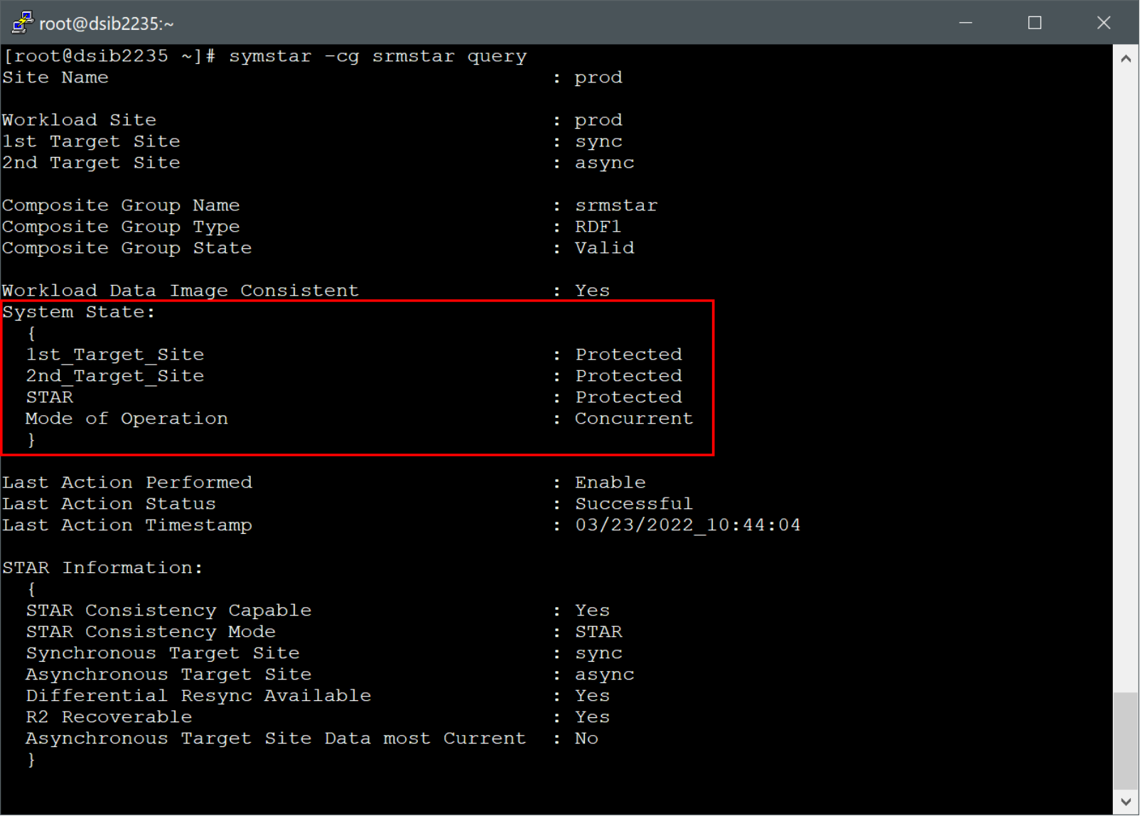
Generally, a good indicator of valid SRDF/Star pair status is shown in the “Status” column in a given array pair. If the “Status” column shows a blue directional arrow with “Forward”, the RDF Pair State is valid for Planned Migration. This is slightly different than with 2-site SRDF however, as 3-site SRDF has additional limitations on what state the devices can be in to allow failover which are not reflected within “Status” column. Not only do the device pairs need to be replicating, but they need to be consistent. In SRDF/Star terminology, this means that both the Asynchronous site and the Synchronous site must be in the “Protected” state and SRDF/Star must be in the overall “Protected” state. An example of a valid configuration is seen in Figure 132.
Figure 132. SRDF/Star valid state
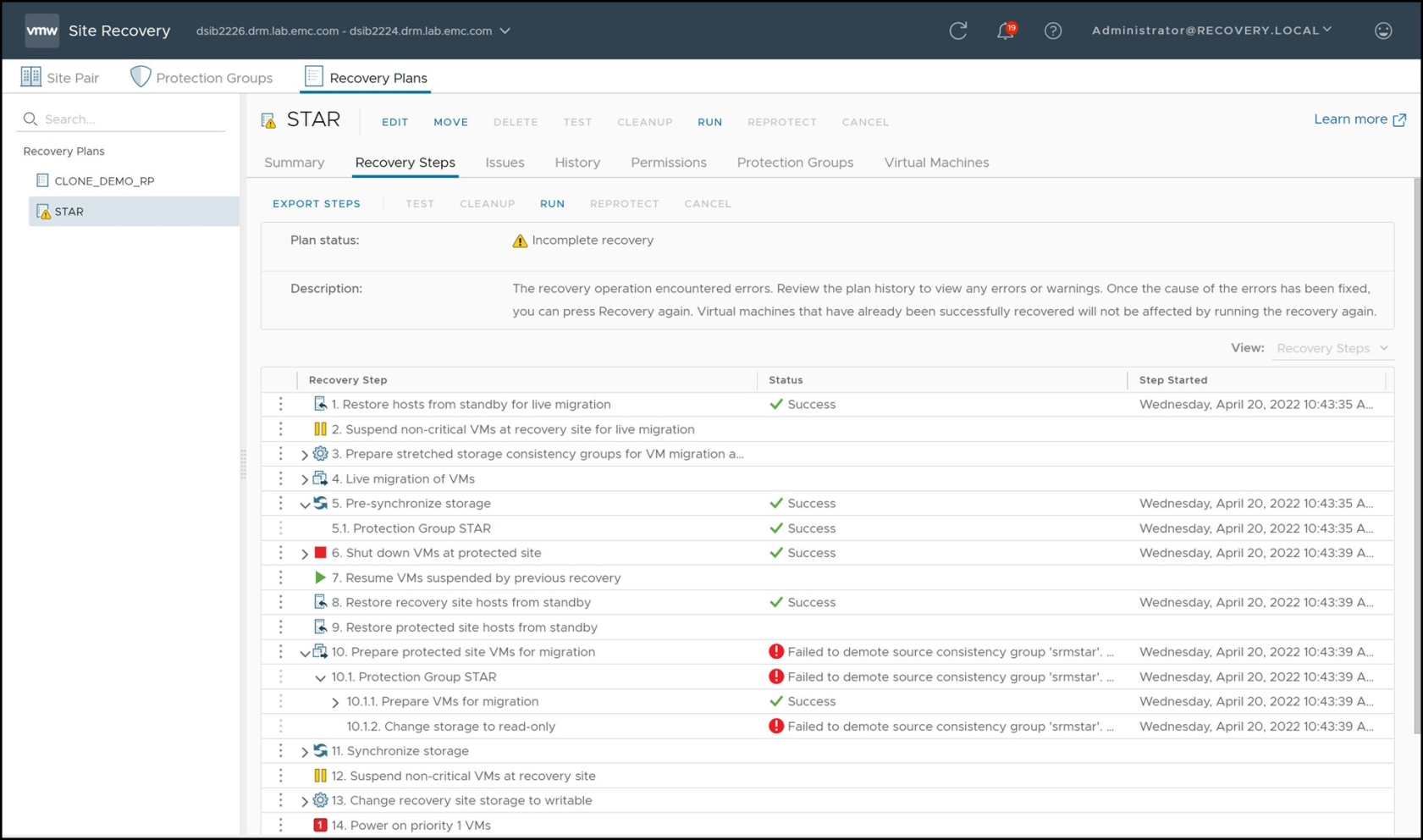
The SRA requires that SRDF/Star is “Protected” so if either site is not in the “Protected” state, SRDF/Star cannot be in the proper state and Planned Migration will fail. The SRDF SRA log will report errors such as those below, after a failed recovery plan due to invalid SRDF/Star state:
[01/16 13:18:00 16212 0569
SraStarGroup::IsValidStarState] STAR Group state is Unprotected.
[01/16 13:18:00 16212 0985
SraStarGroup::ValidateInputDevices] [WARNING]: The STAR state is not valid. Exiting
[01/16 13:18:00 16212 3018
PrepareFailoverCommand::RunOnGroup] [ERROR]: Input device validation succeeded but one/many of the adapter's conditions is not met. Exiting with failure
Errors of a failed recovery plan due to an invalid SRDF/Star state will take the form of “Failed to demote source consistency group ‘xxxx’” as shown in Figure 133.
Figure 133. Failed planned migration due to invalid SRDF/Star state
If the “Status” column shows a different message, such as green arrows with “Failover in Progress”, either manual intervention is required or the Disaster Recovery option needs to be selected. Planned migration will never be allowed in this state.
While the “Status” column is, in general, a good indicator of RDF pair states, it is inadequate to cover the many diverse possibilities of RDF pair states. Therefore, it is advisable to use Solutions Enabler to determine the exact status. A valid SRDF/Star group for Planned Migration is when the 1st Target (synchronous site), the 2nd Target (the asynchronous site) and SRDF/Star state itself all report as “Protected”.
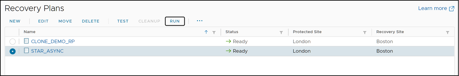
At this point, a planned migration can be initiated by selecting the appropriate recovery plan and the selecting the “Recovery” link as can be seen in Figure 134.
Figure 134. Initiating a planned migration with SRM
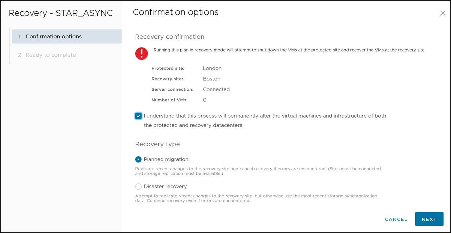
Once the Recovery link has been selected, a short confirmation wizard appears asking to confirm the initiation of the recovery operation and in which mode the recovery plan should be run. This screen is shown in Figure 135.
Figure 135. Recovery operation confirmation wizard
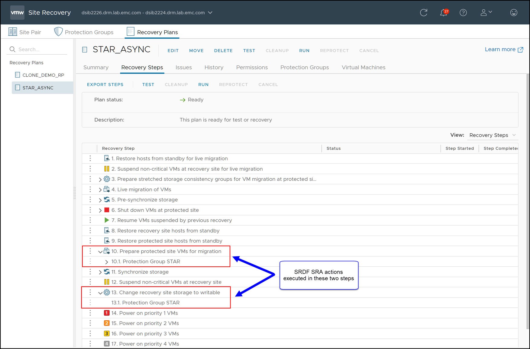
As soon as the wizard completes the recovery operation will commence. During the steps “Prepare Protected Site VMs for Migration” and “Change Recovery Site Storage To Writable”, as shown in Figure 136, the SRDF SRA performs the necessary Star operations on the devices in the protection group to failover.
Figure 136. Steps of a recovery plan in SRM
The following two tables describe the steps for recovery with Concurrent SRDF/Star. The tables have seven columns:
- SRDF SRA Step #: The chronological order of the operations initiated by the SRDF SRA during recovery.
- Issuing SRDF SRA and Solutions Enabler: Due to certain Star requirements certain operations must be issued from certain Solutions Enabler server (for example symstar halt must be issued by the workload Solutions Enabler server). Therefore the first few operations are issued by the protected site SRDF SRA and consequently the protected site Solutions Enabler server. If an error occurs during a given operation refer to the specified SRDF SRA server or Solutions Enabler server listed for that operation for the correct logs.
- Step Detail: The description of the SRDF SRA operation.
- Resulting SRDF/SRA State: The overall state of the SRDF/Star configuration after the listed SRDF SRA operation has completed.
- Site A after step: The state of the original workload site after the operation.
- Site B after step: The state of the original synchronous target site after the operation.
- Site C after step: The state of the original asynchronous target site after the operation.
For Concurrent SRDF/Star recovery to the Synchronous site, the SRA performs the steps listed in Table 20. For Concurrent SRDF/Star recovery to the Asynchronous site, the SRA performs the steps listed in Table 21.
Table 19. Concurrent SRDF/Star steps for Synchronous Recovery
SRDF SRA
step #
Issuing SRDF SRA and Solutions Enabler
Step detail
Resulting SRDF/Star state
Site A after step
Site B after step
Site C after step
1
Protected site
[OPTIONAL] Create protected site gold copies
Protected
Workload
Protected
Protected
2
Protected site
[OPTIONAL] Remove R1 devices from storage group
Protected
Workload
Protected
Protected
3
Protected site
Halt Star
Unprotected
Workload
Halted
Halted
4
Recovery site
[OPTIONAL] Create recovery site gold copies
Unprotected
Workload
Halted
Halted
5
Recovery site
Switch Workload site. The original Workload site is now the Sync site and vice versa.
Unprotected
Disconnected
Workload
Disconnected
6
Recovery site
Connect Sync target site
Unprotected
Connected
Workload
Disconnected
7
Recovery site
Connect Async target site
Unprotected
Connected
Workload
Connected
8
Recovery site
Protect Sync target site
Unprotected
Protected
Workload
Connected
9
Recovery site
Protect Async target site
Unprotected
Protected
Workload
Protected
10
Recovery site
Enable Star
Protected
Protected
Workload
Protected
11
Recovery site
[OPTIONAL] Add R2 devices to storage group
Protected
Protected
Workload
Protected
Table 20. Concurrent SRDF/Star steps for Asynchronous Recovery
SRDF SRA
step #
Issuing SRDF SRA and Solutions Enabler
Step detail
Resulting SRDF/Star state
Site A after step
Site B after step
Site C after step
1
Protected site
[OPTIONAL] Create protected site gold copies
Protected
Workload
Protected
Protected
2
Protected site
[OPTIONAL] Remove R1 devices from storage group
Protected
Workload
Protected
Protected
3
Protected site
Halt Star
Unprotected
Workload
Halted
Halted
4
Recovery site
[OPTIONAL] Create recovery site gold copies
Unprotected
Workload
Halted
Halted
5
Recovery site
Switch Workload site. The original Workload site is now the Async site and vice versa.
Unprotected
Disconnected
Disconnected
Workload
6
Recovery site
Connect Async target site
Unprotected
Disconnected
Connected
Workload
7
Recovery site
Connect Sync target site
Unprotected
Connected
Connected
Workload
8
Recovery site
Protect Async target site
Unprotected
Connected
Protected
Workload
9
Recovery site
[OPTIONAL] Add R2 devices to storage group
Unprotected
Connected
Protected
Workload
Readers may note an important difference between the Asynchronous recovery and the Synchronous recovery, that being the end state of Star is not fully protected in an Asynchronous recovery unlike Synchronous recovery. This is due to the fact that when the workload site is located in the tertiary site, which is at an asynchronous distance from the other two sites, it cannot replicate in a synchronous fashion to the Synchronous target site. Without a Synchronous replication site, Star cannot be fully protected. Consequently the SRDF SRA can only “Connect” the Synchronous site which leaves it in Adaptive Copy Disk mode.
Unlike 2-site SRDF or Non-Star 3-site, the SRA will always reverse the direction of replication and enable consistency during the failover process. For Non-Star SRDF solutions, this replication reversal is reserved for the “Reprotect” operation. Due to the requirements inherent in SRDF/Star these steps are included in the failover process.
Once the SRDF/Star switch workload process has completed, the Synchronous target site devices are now write enabled so the devices will be mounted and the virtual machines will be registered and powered-on. The SRDF/Star switch workload process will swap the RDF personalities of the devices and change the site definitions within the SRDF/Star configuration. With Concurrent SRDF/Star, the R1 devices will become R2 devices. Similarly, the R2 devices (on the Synchronous site OR the Asynchronous site depending on the configuration) are now R1 devices.
In addition to the R2/21 devices being mounted on the recovery-side ESXi hosts, the R1 volumes will be unmounted and detached from the protection-side ESXi hosts.
When the VMFS volumes on the R2 devices are mounted, the ESXi kernel must resignature the VMFS first because it is seen as a copy due to its invalid signature. The reason for the invalid signature, and therefore the subsequent resignaturing, is due to the fact that the R1 and R2 devices have different world-wide names (WWNs) but an identical VMFS volume. The VMFS volume was (most likely) originally created on the R1 device and the signature of the VMFS is based, in part, on the WWN of the underlying device. Since the WWN changes between the R1 and the R2 and the signature is copied over, the ESXi kernel will identify a WWN/VMFS signature mismatch and resignature.
The VMware kernel automatically renames VMFS volumes that have been resignatured by adding a “SNAP-XXXXXX” prefix to the original name to denote that it is a copied file system. VMware Site Recovery Manager provides an advanced setting (disabled by default), storageProvider.fixRecoveredDatastoreNames, that will cause this suffix to be automatically removed during the recovery plan. Check this option on the recovery site to enable this automatic prefix removal behavior.
Disaster Recovery: Concurrent SRDF/Star
The option “Disaster Recovery” should be selected for recovery when there are issues with the infrastructure that will prevent a graceful recovery of virtual machines from a local vCenter to a remote vCenter. Unlike the “Planned Migration” option, most errors that the recovery plan encounters will be ignored by SRM. The only errors that will prevent a recovery in disaster recovery mode are failures in the recovery site infrastructure. Anything from minor errors to complete failure of the protected site infrastructure will not prevent recovery.
If possible, the “Planned Migration” is preferable as it will more likely allow for a clean subsequent reprotection and/or failback. Therefore, if errors are encountered an earnest attempt to remediate them should be made. If these errors cannot be fixed (due to equipment failure or if time is of the essence and the virtual environment must be recovered as quickly as possible) the “Disaster Recovery” option should be selected.
This section will discuss disaster recovery failover in two parts:
- Recovery after failure of compute environment
- Recovery after failure of storage and compute environment