
Configure the appliance
Configure the appliance
-
Configure the appliance as follows:
- Log in to the PowerProtect Data Manager Appliance configuration UI by entering the following URL in your browser’s address bar:
https://192.168.100.100
The PowerProtect Data Manager Appliance configuration UI is displayed.
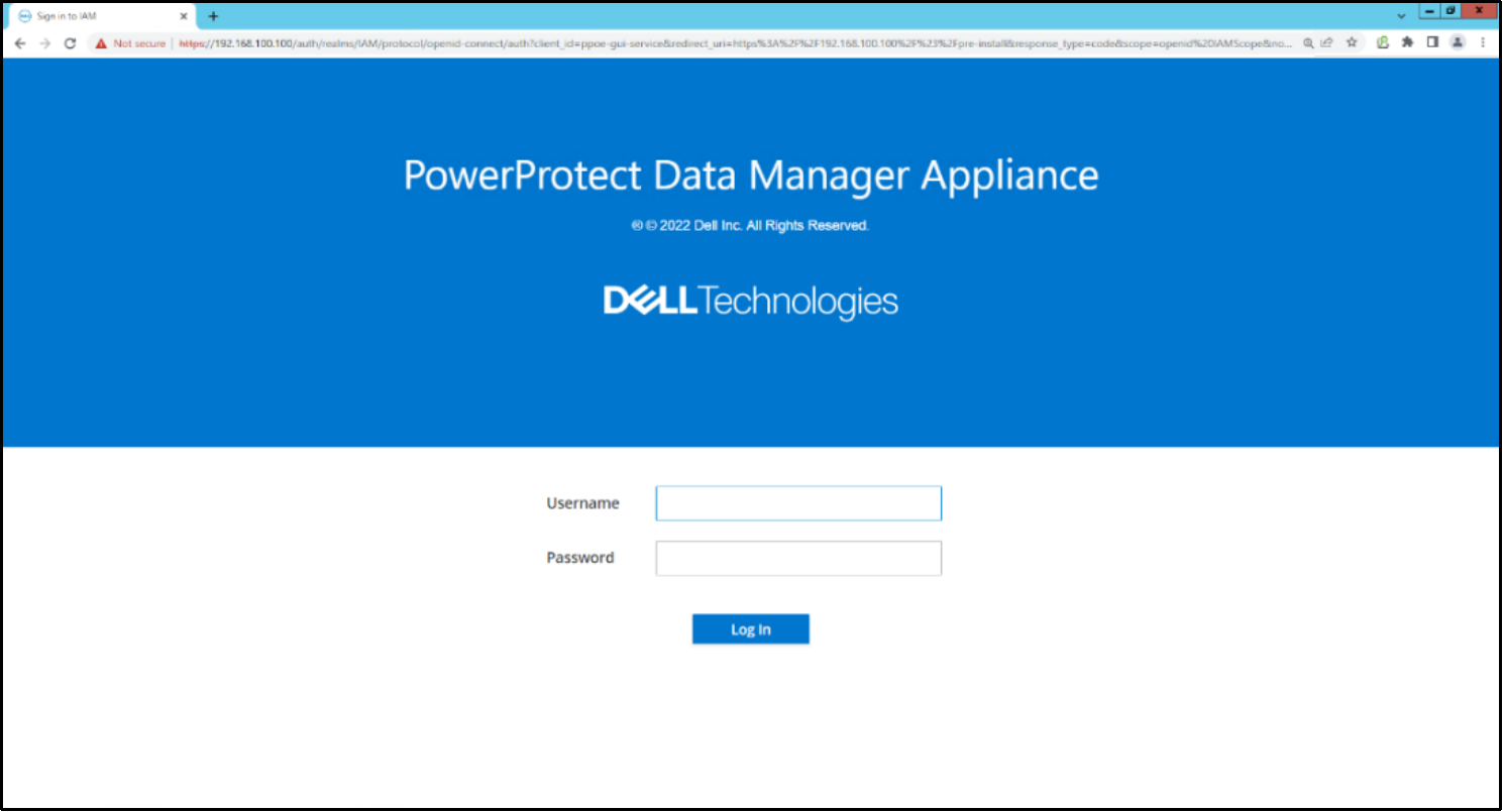
Figure 13. PowerProtect Data Manager Appliance configuration UI
- In the configuration UI, log in using the administrator credentials, where the password is dm@ followed by the appliance serial number (PSNT).
Note: The PSNT is on the pull-out information tag on the back of the server, to the right of the PSUs.
For example, if the PSNT is DPDIH220124121, the password would be dm@DPDIH220124121.
- Click Login.
- On the Create Secure Credentials page, perform the following actions:
- In the Current Password field, enter the appliance serial number (PSNT) with the prefix dm@.
By default, the New Admin Username field is set to admin.
- In the New Password and Reenter New Password fields, specify a new admin user password.
After deployment, use the updated password to log in to PowerProtect Data Manager Appliance.
Ensure that the password meets the following requirements:
- Minimum of nine characters and a maximum of 16 characters
- At least one numeric character (0-9)
- At least one uppercase character (A-Z)
- At least one lowercase character (a-z)
- At least one special character from the following list of acceptable characters:
!@#$%^&*()<>?
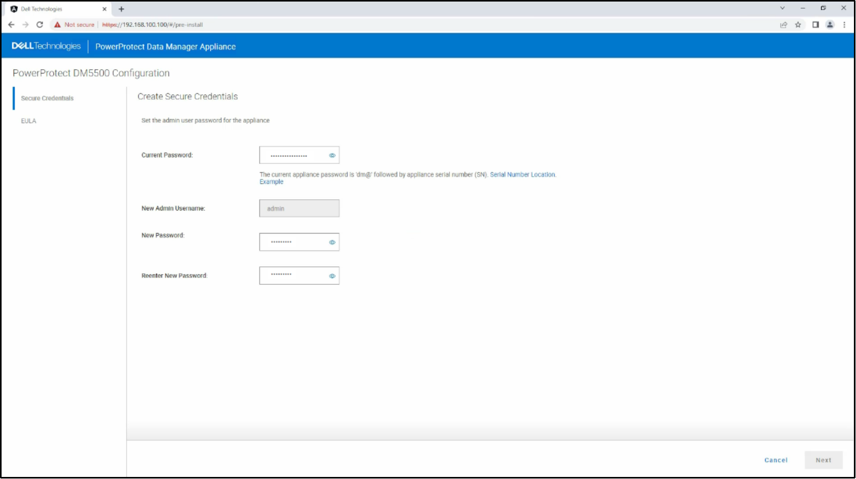
Figure 14. PowerProtect Data Manager Appliance credentials
- Click Next.
The End User License Agreement is displayed.
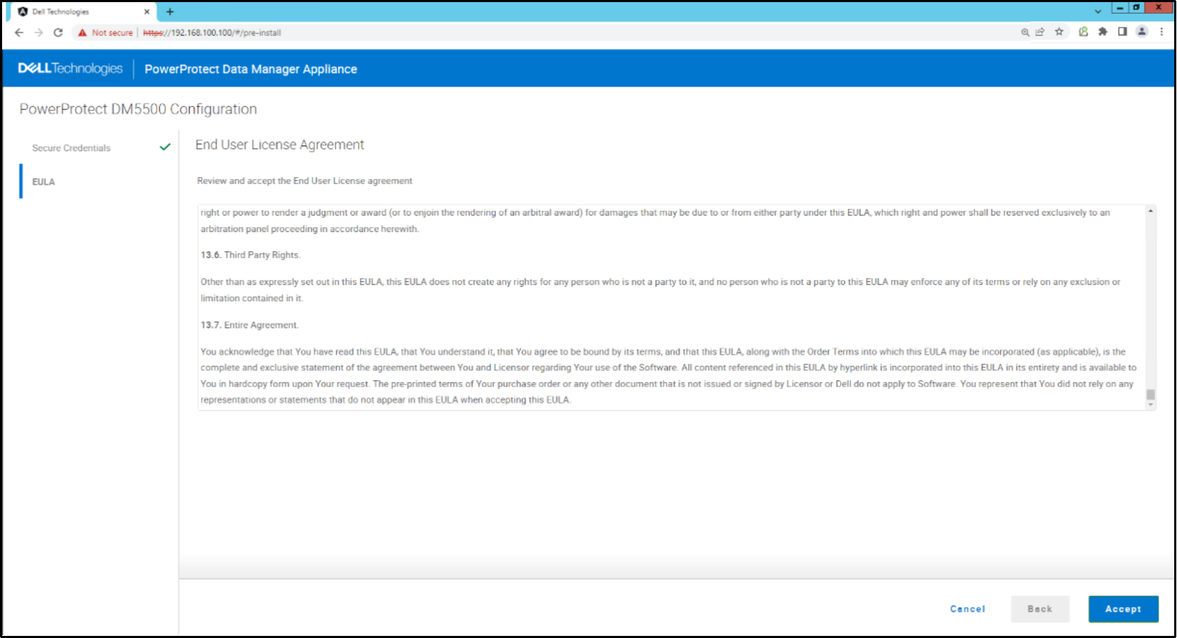
Figure 15. PowerProtect Data Manager Appliance End User License Agreement
- Review the license agreement and click Accept.
The Network page is displayed.
- On the Network page, in the Network section, perform the following actions:
- In the Management IP field, specify an IP address.
- In the Management FQDN field, specify a FQDN name for the management interface.
- In the Management Domain name field, specify a domain name for the management FQDN.
- In the Data IP 1 field, specify an IP address.
- (Optional) In the Data IP 2 field, specify an IP address.
- In the Management VLAN section, perform the following actions:
- In the Management VLAN ID field, specify a numerical VLAN ID.
If the switch port is tagged (trunk mode), provide the correct VLAN ID that corresponds to the customer network. If the switch port is untagged (access mode), use VLAN 0. However, trunk mode is recommended.
- In the Management subnet mask field, specify a subnet mask.
- In the Management Gateway field, specify a gateway IP address.
In the MTU field, the maximum transition units (MTU) value is set to 1500.
- In the Bonding options list, the port bonding configuration is set to Active-Active so that all ports actively load balance the internal network traffic. Active/active bonding does not require any corresponding switch-side settings.
- In the Data VLAN section, perform the following actions:
- Select the separate Data Network checkbox option if you want the data network to be different than the management network. When this checkbox is selected, the Data VLAN ID, Data subnet mask, Data Gateway fields are unpopulated, and the user can key in the corresponding values.
- In the Data VLAN ID field, specify a numerical VLAN ID.
Note: If the switch port is tagged (trunk mode), provide the correct VLAN ID that corresponds to the customer network. If the switch port is untagged (access mode), use VLAN 0. However, trunk mode is recommended.
- In the Data subnet mask field, specify a subnet mask.
- In the Data Gateway field, specify a gateway IP address.
- In the MTU field, the maximum transition units (MTU) value is set to 1500.
- In the Bonding options list, the port bonding configuration is set to Active-Active so that all ports actively load-balance the internal network traffic. Active/active bonding does not require any corresponding switch-side configuration.
- In the Primary DNS Server field, specify a DNS server IP address.
- In the Secondary DNS Server field, optionally specify a second DNS server IP address.
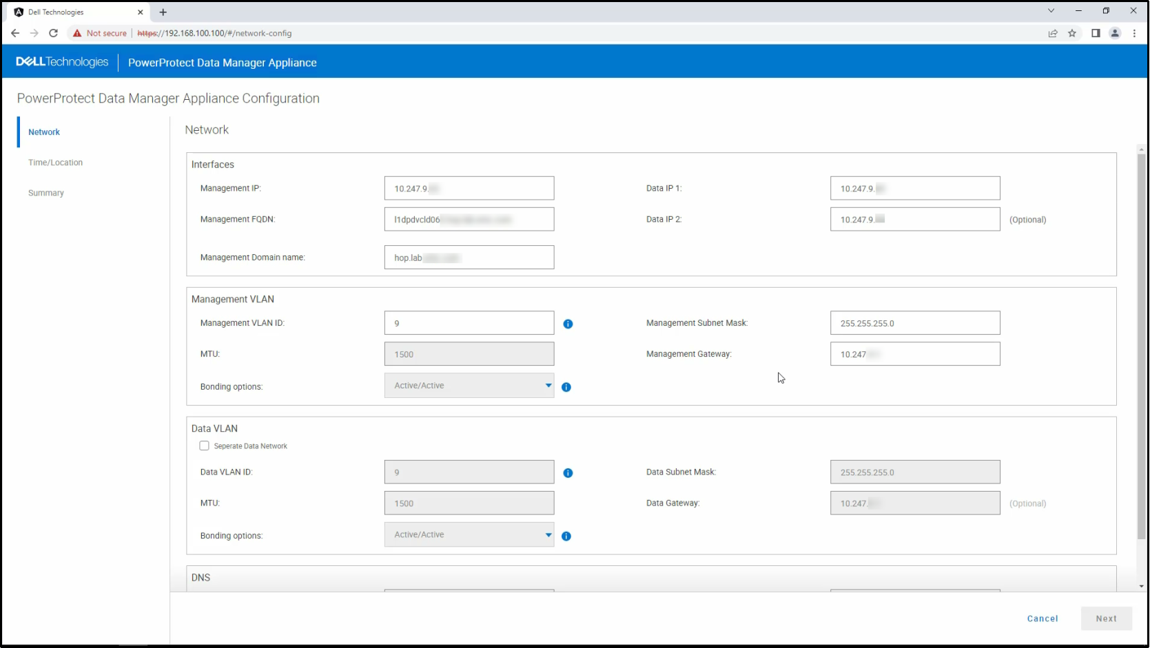
Figure 16. PowerProtect Data Manager Appliance network configuration
- Click Next.
The Time/Location page is displayed.
- On the Time/Location page, perform the following actions:
- From the Time zone list, select the time zone where the system exists.
- In the NTP Servers field, specify the NTP server IP address.
- (Optional) Click + to add a secondary NTP server.
- Click Next.
The iDRAC page is displayed.
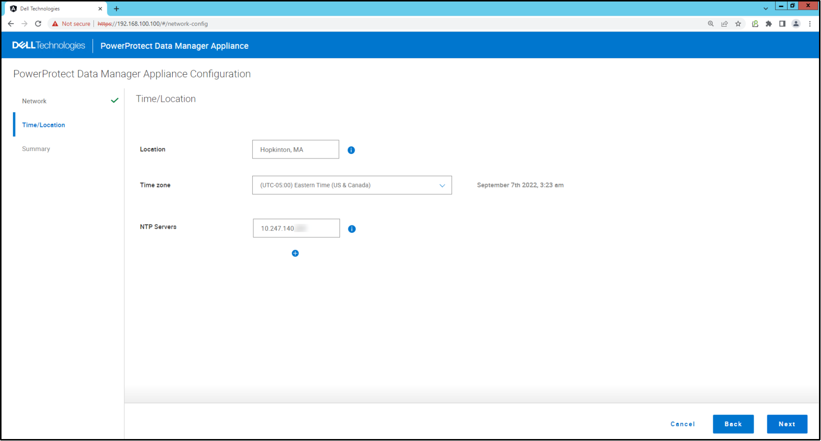
Figure 17. PowerProtect Data Manager Appliance time and location
- On the iDRAC page, create a read-only iDRAC user. This user will allow Dell Support to obtain iDRAC access through the Data Manager Appliance UI after you complete the initial appliance configuration.
On the iDRAC Page, enter the following in the iDRAC User section.
- In the Username field, specify a user name for the iDRAC user.
- In the Password field, specify the password for the iDRAC user.
- In the Re-enter Password field, enter the iDRAC user's password again.
When you create the read-only iDRAC user in this step, internally an iDRAC user with operator role privileges is also created. The operator role iDRAC user can perform actions such as using iDRAC to start up the DM5500. The operator role’s credentials for the iDRAC user are based on the read-only iDRAC user credentials you enter in this step. The operator role iDRAC user credentials that are internally created are:
- Username: <read-only-iDRAC-User-Name>-opr
- Password: <read-only-User-iDRAC-Password> <appliance-serial-number>
As an example, for the read-only iDRAC user, if you entered jsmith as the username and P@ssword4 as the password, the operator role iDRAC user credentials that would be created internally are:
- Username: jsmith-opr
- Password: P@ssword4DPDID220100130
- (Optional) Set up the iDRAC network settings.
Although it is optional, iDRAC configuration is strongly recommended because iDRAC connections are helpful for Dell support engineers to debug and troubleshoot issues.
On the iDRAC page, in the iDRAC Network Settings section, select the Configure network settings checkbox if you want to enable iDRAC for remote system management. If you do not configure the iDRAC network settings, you will only be able to access iDRAC through a cable connection to the DM5500 and a service computer.
To set up the iDRAC network settings, enter the following:
- In the IP Address field, specify the iDRAC IP address.
- In the Subnet Mask field, specify the iDRAC subnet mask.
- In the Gateway field, enter the iDRAC gateway.
Note: If you do not configure the iDRAC IP address during the initial DM5500 configuration, you can configure it post-installation in the PowerProtect Data Manager Appliance UI under Settings > System Configuration as described in the PowerProtect Data Manager Appliance 5.16 Administrator's Guide.
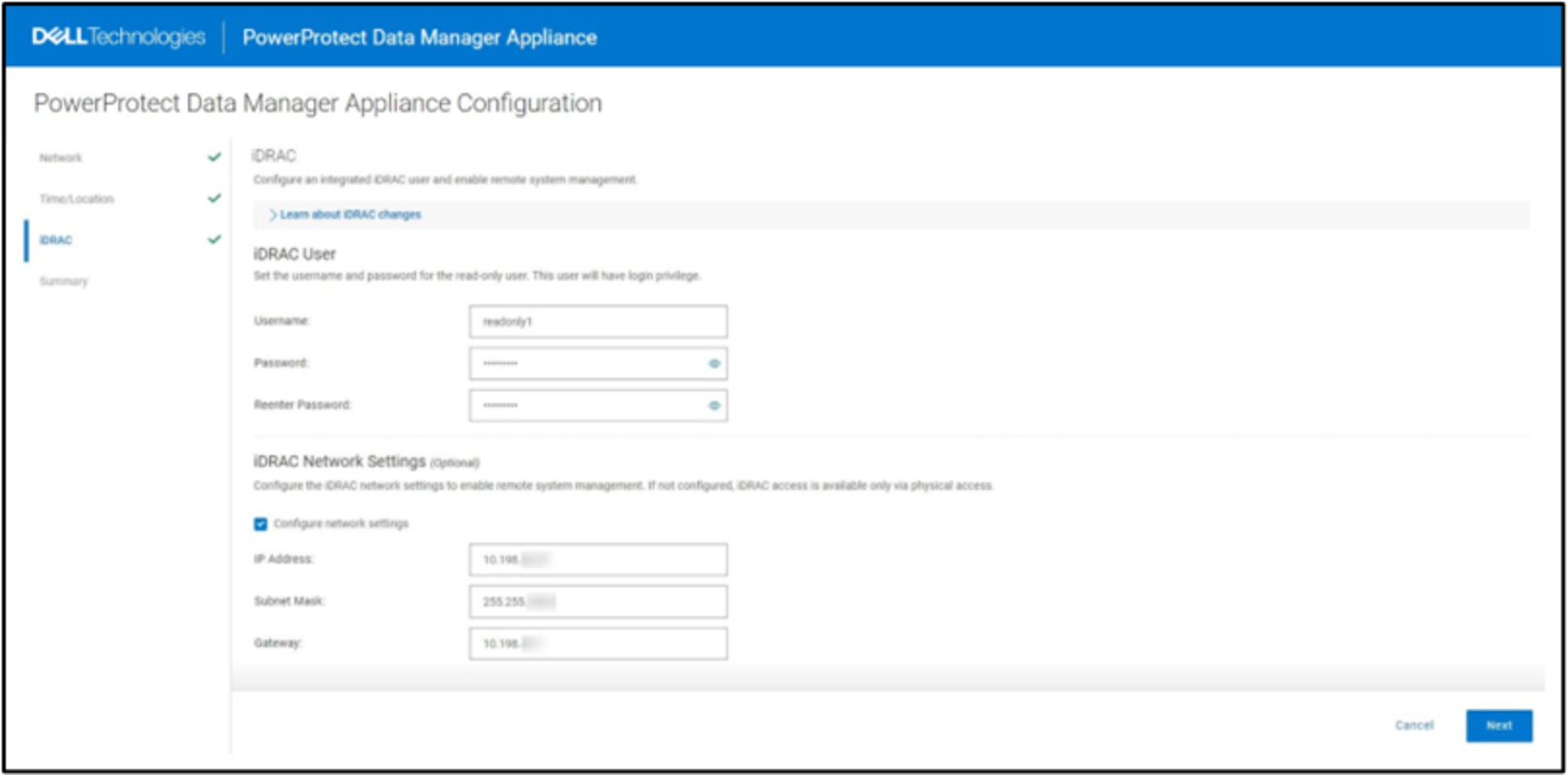
Figure 18. PowerProtect Data Manager iDRAC IP Address settings
- Click Next.
The Summary page appears.
- On the Summary page, click Apply to start the deployment process.
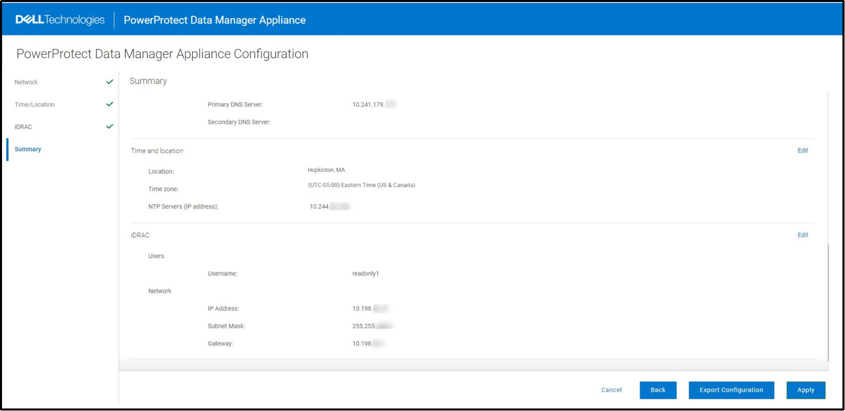
Figure 19. PowerProtect Data Manager Appliance Summary page
The appliance displays a progress bar showing the status of the configuration.
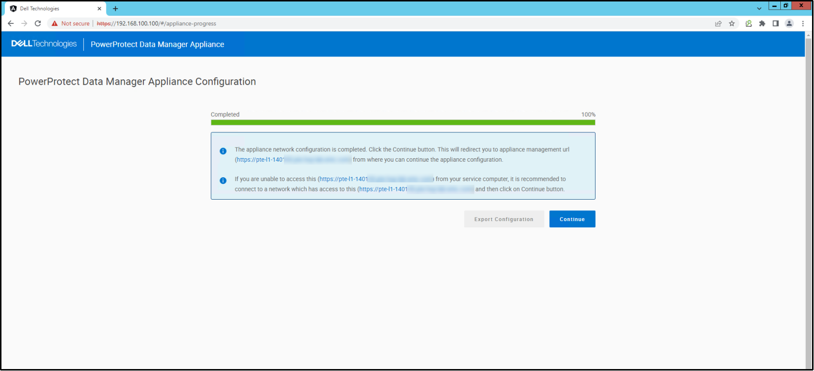
Figure 20. PowerProtect Data Manager Appliance Is successfully deployed.
- When the appliance is successfully deployed and configured, click Continue.
The PowerProtect Data Manager Appliance login page is displayed.