
PowerProtect Data Manager Appliance hardware composition
PowerProtect Data Manager Appliance hardware composition
-
Dell PowerProtect Data Manager Appliance is designed with a purpose-built platform, that provides resiliency for the data protection services, ensuring the highest levels of application availability.
PowerProtect Data Manager Appliance is a 2U server with two drive bays. Each drive bay has 12 drives for a total of 24 drives. Other components include:
- 2 x 5218R 20-core, 2.1 GHz Cascade Lake Intel CPUs
- 384 GB RAM or 12 x 32 GB DIMMs
- 20 x 12 TB hard drives
- 2 for internal storage, 6+2 base for protection storage, 10 expansions
- 12 TB to 96 TB usable at capacity in 2U (cloud tier @ 2:1)
- 2 x 1 TB (960 GB) SSD for operating system/boot
- 1 x 1.92 TB, 1 x 3.84 TB cache SSD (metadata cache, IA/IR)
- Mirrored IDSDM 16 GB SD cards for boot recovery
- Hardware-assisted compression card
- 10 GbE/25 GbE networking
- 12 Gbps SAS card (Dell HBA 355e-s)
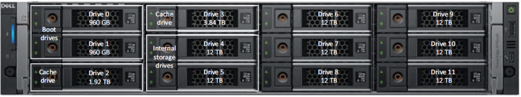
Figure 2. Front disk layout (drive bay 1)
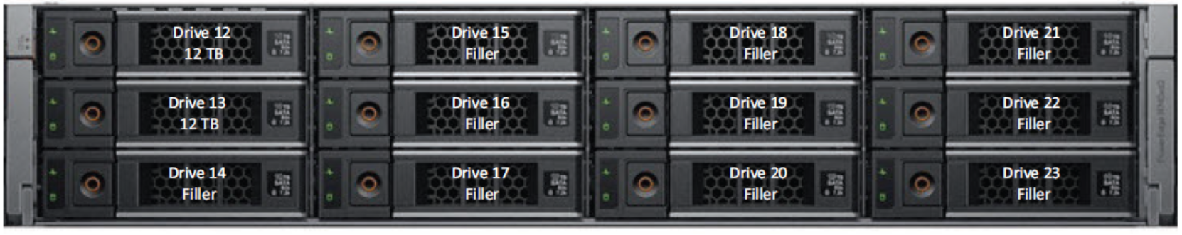
Figure 3. Middle disk layout (drive bay 2)
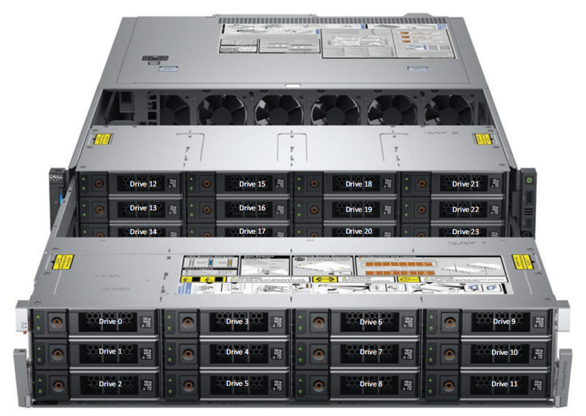
Figure 4. View of drive bay extended
Note: Customers can order the system based on a usable capacity of 24 TB to 256 TB. The drive bays are populated depending on the order type. For example, if the customer orders a system with 24 TB capacity, slots 0 to 13 are populated; a system with 96 TB capacity has both drive bays fully populated.
A system with a 24 TB configuration is shipped with only one SSD (1.92 TB) used for the cache tier; slot 3 is empty. Anything beyond 96 TB, the customer must purchase additional disk enclosures (1-3) to meet the specific capacity point.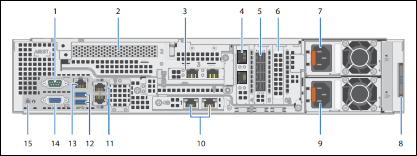
Figure 5. Rear view of PowerProtect Data Manager Appliance
The following table describes the back panel features of PowerProtect Data Manager Appliance:
Table 1. PowerProtect Data Manager Appliance back panel
Figure 5 callout
Description
1
Serial port
2
Intel hardware-assisted compression (QAT) card (PCIe slot 2)
3
Dual or quad port HBA (PCIe slot 3)
Can be configured to run as two 10/25 GbE SFP28 ports, two 10 GbE SFP+ ports, or four 10 GBT ports
4
Dual or quad port HBA (PCIe slot 4)
Can be configured to run as two 10/25 GbE SFP28 ports, two 10 GbE SFP+ ports, or four 10 GBT ports
5
Dual-port HBA (2 x SAS 12 Gbps) (PCIe slot 5)
6
Filler (unused) PCIe expansion card (PCIe slot 6)
7
Power supply unit (PSU 1)
PSU 1 can be 1100 W or 1600 W but must be the same wattage as PSU 2.
8
Information tag with the DM5500 Serial Number (PSNT)
The pull-out information tag contains a white label with the 14-character DM5500 serial number. The complete serial number (PSNT) plus a prefix of dm@ is the initial default password for the PowerProtect Data Manager Appliance UI.
9
Power supply unit (PSU 2)
PSU 2 can be 1100 W or 1600 W but must be the same wattage as PSU 1.
10
LAN on motherboard (LOM) Ethernet port (2) (PCIe slot 1)
Can be configured to run as 10/25 GbE SFP28, 10 GbE SFP+, or 10 GBT
11
Ethernet port (Gb1); service port used for initial DM5500 login
You can use this Gb1 port or the Gb2 port for the initial DM5500 login.
12
USB 3.0 port (2)
13
iDRAC9 dedicated network port
14
VGA port
15
System identification button
Note: For information about hardware and software requirements for installation and the procedure to rack and stack the appliance, see the PowerProtect Data Manager Appliance DM5500 5.160.0 Installation Guide.
Expansion enclosure front view
The front of the enclosure contains an LED panel and provides access to the service tag. Removing the front bezel provides access to the enclosure drives.
The enclosure supports twelve 8 TB 3.5 in. drives, mounted horizontally in the chassis.
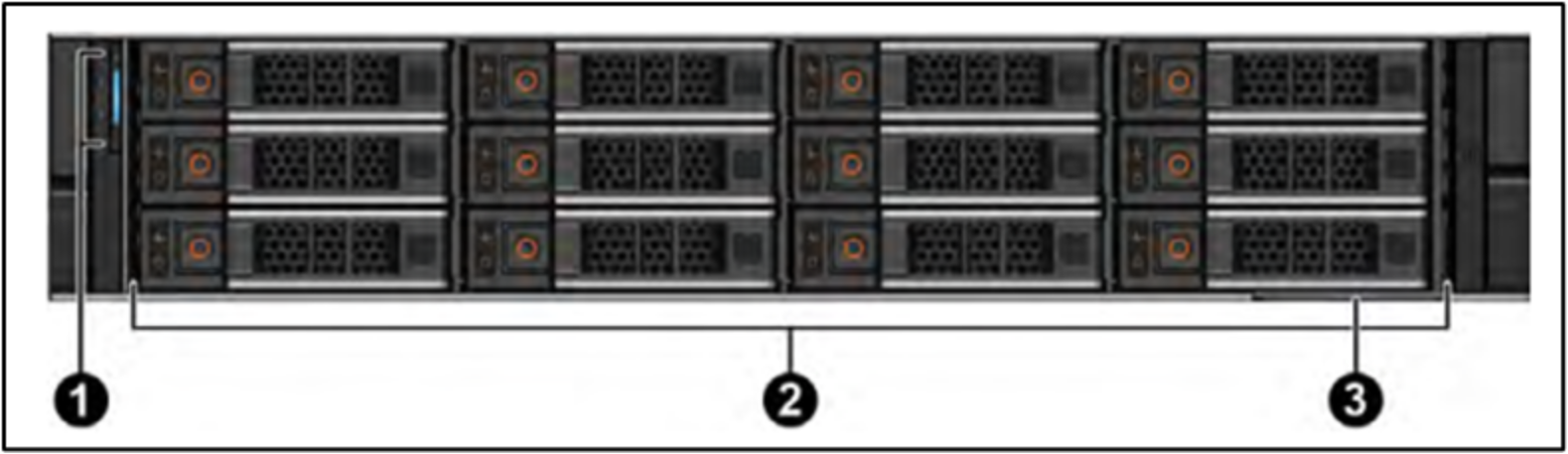
Figure 6. Expansion enclosure front view
Table 2. Expansion enclosure front view callouts
Figure 6
calloutsDescription
1
LED Panel
2
Drives
3
Service Tag
Expansion enclosure rear view
The expansion enclosures contain two hot-swappable enclosure management modules: (EMMs) and two hot-swappable PSUs.
Each expansion enclosure is identified by a unique Service Tag and Express Service. The Service Tag and Express Service Code are found on the front of the system by pulling out the service tag. This information is used to route support calls to appropriate personnel. The QRL code on the service tag contains information unique to the system.
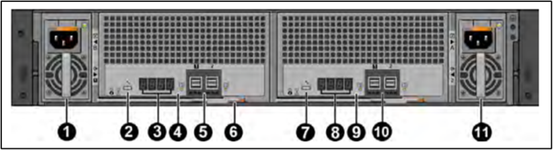
Figure 7. Expansion enclosure rear view
Table 3. Expansion enclosure rear view callouts
Figure 7 callouts
Description
1
AC PSU-B
2
Debug port
3
EMM LEDs used to identify enclosure number (4)
4
EMM 1 (EMM-A/Slot 1)
5
SAS ports (2)
- Port 1 dedicated host port
- Port 2 dedicated expansion enclosure port
6
Latch/handle
7
Debug port
8
EMM LEDs used to identify enclosure number (4)
9
EMM 2 (EMM-B/Slot 2)
10
SAS ports (2)
- Port 1 dedicated host port
- Port 2 dedicated expansion enclosure port
11
AC PSU-A
Note: For information about expansion enclosures, see the PowerProtect Data Manager Appliance DM5500 5.16.0.0 Installation Guide.