Home > Storage > PowerFlex > White Papers > Dell PowerFlex: Introduction to Replication > Remote replication networking
Remote replication networking
-
Network latency should not exceed 200 ms between peered PowerFlex systems. The potential of exceeding this limit is greater over a WAN vs a LAN. Write-folding may reduce the amount of data shipped to the target journal, but the savings cannot easily be predicted. If the available bandwidth is exceeded, journal intervals will back up, resulting in an increase in the journal volume size as well as in increase in RPO. Thoroughly test the latency and throughput limits of network links and keep the replication bandwidth under your known thresholds.
Journal data is shipped between source and target SDRs, first, at the replication pair initialization phase and, second, during the replication steady state phase. Take care to ensure that adequate bandwidth exists between the source and target SDRs, whether over LAN or WAN. The potential for exceeding available bandwidth is greatest over WAN connections. While write-folding might reduce the amount of data to be shipped to the target journal, it cannot always be easily predicted. If the available bandwidth is exceeded, the journal intervals will back up, increasing both the journal volume size and the RPO.
We recommend that the sustained write bandwidth of all volumes being replicated does not exceed 80 percent of the total available WAN bandwidth. If the peer systems are mutually replicating volumes to one another, the peer SDR<->SDR bandwidth must account for the requirements of both directions simultaneously. For additional help calculating the required WAN bandwidth for specific workloads, see the PowerFlex Sizer.
Note: The sizer tool is an internal tool available for Dell employees and partners. External users should consult with their technical sales specialist if WAN bandwidth sizing assistance is needed.
Leaving a 20 percent margin for replication traffic over a WAN allows for application I/O bursts and for the initial syncing of new volumes added to or reactivated in RCGs.
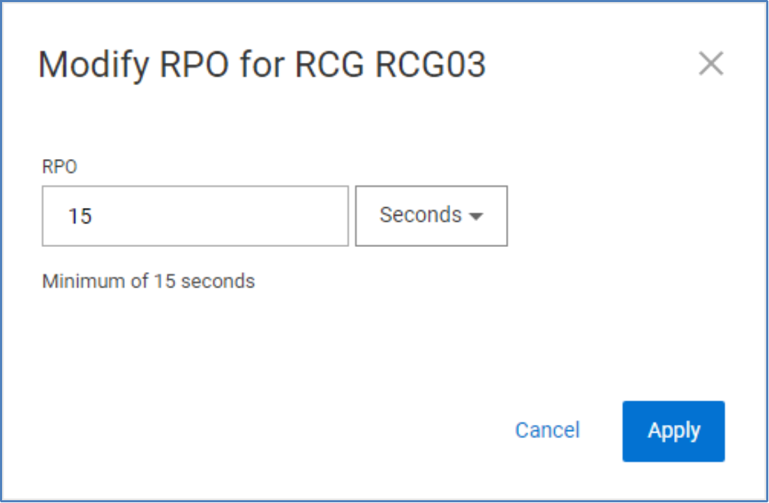
In certain cases, when latency is high, you need to increase the RPO of your RCGs. You can change the RPO using PowerFlex Manager, scli, or REST API.

Figure 20. Modify RCG RPO
Networking implications for replication health
It is possible to have write peaks that exceed the recommended “0.8 * WAN bandwidth,” but they should be short. The journal size must be large enough to absorb these write peaks.
Similarly, the journal volume capacity should be sized to accommodate link outages between peer systems. A 1-hour outage might be reasonably expected, but we encourage users to plan for 3 hours. Obviously, the RPO will increase while the link is down, and sufficient journal space is required to account for the writes during the outage. Using the PowerFlex sizer for such planning is best, but, in general, calculate the journal capacity as WAN bandwidth x link downtime. For example, if the WAN link is 2 x 10 Gb (about 2 GB/sec) and the planned downtime is 1 hour, the journal size would be 2 x 3,600, or 7 TB.
When a WAN link is restored, the 20 percent bandwidth headroom allows the system to catch up to its original RPO target.
Note: The volume data shipped in the journal intervals is not compressed. In PowerFlex, compression is for data at rest. In fine-granularity storage pools, data compression takes place in the SDS service after the data has been received from an SDC (for nonreplicated volumes) or an SDR (for replicated volumes). The SDR is unaware of and agnostic to the data layout on either side of a replica pair. If the destination, or target, volume is configured as compressed, the compression takes place in the target system SDSs as the journal intervals are being applied.
Routing and firewall considerations for remote replication
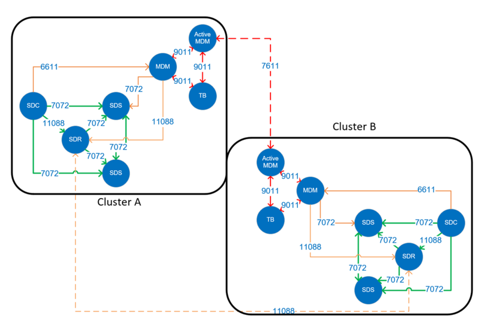
TCP/IP port considerations described the use of TCP/IP ports for MDM communications (7611) between replicating clusters and SDR communications (11088) used in transporting replication journal logs.

Figure 21. MDM port and firewall considerations
For replication use cases involving distant clusters, we need interconnectivity for these IP ports provided over routed networks. The best practice for networking in this situation is to reserve two networks for intracluster SDR and MDM communications.
PowerFlex asynchronous replication usually happens over a WAN between physically remote clusters that do not share the same address segments. If the default route is not suitable to properly direct packets to the remote SDR IP addresses, configure static routes. The static routes should indicate either the next hop address or the egress interface, or both, for reaching the remote subnet.
For example: X.X.X.X/X via X.X.X.X dev interface
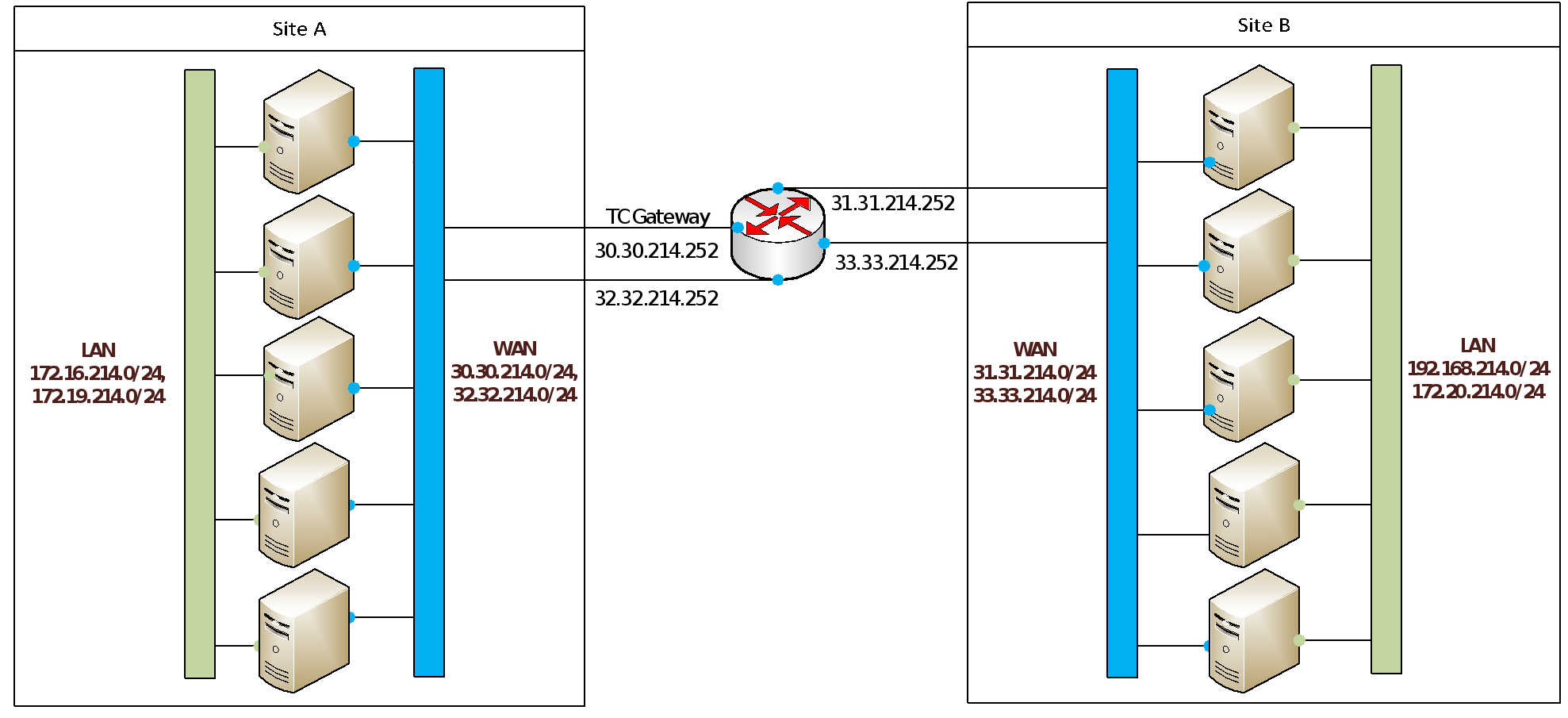
Consider a small system with a few nodes on each side. Each node has four network adapters, two of which are configured with IP addresses for communication internal to the PowerFlex cluster. The second set of network adapters is configured with IP addresses for site-to-site, external communication.
In this example, we tell the nodes to access the WAN subnets for the other side through a specified gateway. From source Site A, the network interfaces enp130s0f0 and enp130s0f1 are configured with addresses in the 30.30.214.0/24 and the 32.32.214.0/24 ranges, respectively. We can configure a route-interface file for each to direct packets for the remote networks over the specified gateway and interface.
route-enp130s0f0 contents 31.31.0.0/16 via 30.30.214.252 dev enp130s0f0
route-enp130s0f1 contents 33.33.0.0/16 via 32.32.214.252 dev enp130s0f1
Packets intended for the remote network 31.31.214.0/24 are directed through the next hop address at gateway IP 30.30.214.252, and similarly for packets destined for 33.33.214.0/24.

Figure 22. WAN topology example for PowerFlex replication
The details of static route configuration will vary with your operating system or hypervisor and overall network architecture, but the general principle is the same.
