
On the MX9116n FSE and MX5108n, server-facing interfaces are internal and are enabled by default. To view the backplane port connections to servers, use the show inventory media command.
In the output, a server-facing interface displays INTERNAL as its media. A FIXED port does not use external transceivers and always displays as Dell EMC Qualified true.
OS10# show inventory media
--------------------------------------------------------------------------------
System Inventory Media
--------------------------------------------------------------------------------
Node/Slot/Port  Category    Media                      Serial-Number  Dell EMC-Qualified
--------------------------------------------------------------------------------
1/1/1             FIXED      INTERNAL                                      true
1/1/2             FIXED      INTERNAL                                      true
1/1/3             FIXED      INTERNAL                                      true
1/1/4             FIXED      INTERNAL                                      true
1/1/5             FIXED      INTERNAL                                      true
1/1/6             FIXED      INTERNAL                                      true
1/1/7             FIXED      INTERNAL                                      true
1/1/8             FIXED      INTERNAL                                      true
1/1/9             FIXED      INTERNAL                                      true
1/1/10            FIXED      INTERNAL                                      true
1/1/11            FIXED      INTERNAL                                      true
1/1/12            FIXED      INTERNAL                                      true
1/1/13            FIXED      INTERNAL                                      true
1/1/14            FIXED      INTERNAL                                      true
1/1/15            FIXED      INTERNAL                                      true
1/1/16            FIXED      INTERNAL                                      true
1/1/17         QSFP28-DD  QSFP28-DD 200GBASE 2SR4 AOC  TW04829489D0007     true
1/1/18         QSFP28-DD  QSFP28-DD 200GBASE 2SR4 AOC  TW04829489D0007     true
1/1/19            Not Present
1/1/20            Not Present
1/1/21            Not Present
--------------------- Output Truncated ----------------------------------------
1/1/37         QSFP28-DD  QSFP28-DD 200GBASE 2SR4 AOC  TW04829489J0021     true
1/1/38         QSFP28-DD  QSFP28-DD 200GBASE 2SR4 AOC  TW04829489J0021     true
1/1/39         QSFP28-DD  QSFP28-DD 200GBASE 2SR4 AOC  TW04829489J0024     true
1/1/40         QSFP28-DD  QSFP28-DD 200GBASE 2SR4 AOC  TW04829489J0024     true
1/1/41         QSFP28     QSFP28    100GBASE CR4 2M    CN0APX0084G1F05     true
1/1/42         QSFP28     QSFP28    100GBASE CR4 2M    CN0APX0084G1F49     true
--------------------- Output Truncated ----------------------------------------
To view the server-facing interface port status, use theshow interface status command. Server-facing ports are numbered 1/1/1 to 1/1/16.
For the MX9116n FSE, servers that have a dual-port NIC connect only to odd-numbered internal Ethernet interfaces; for example, a MX740c in slot one would be 1/1/1, and a MX840c in slots five and six occupies 1/1/9 and 1/1/11.
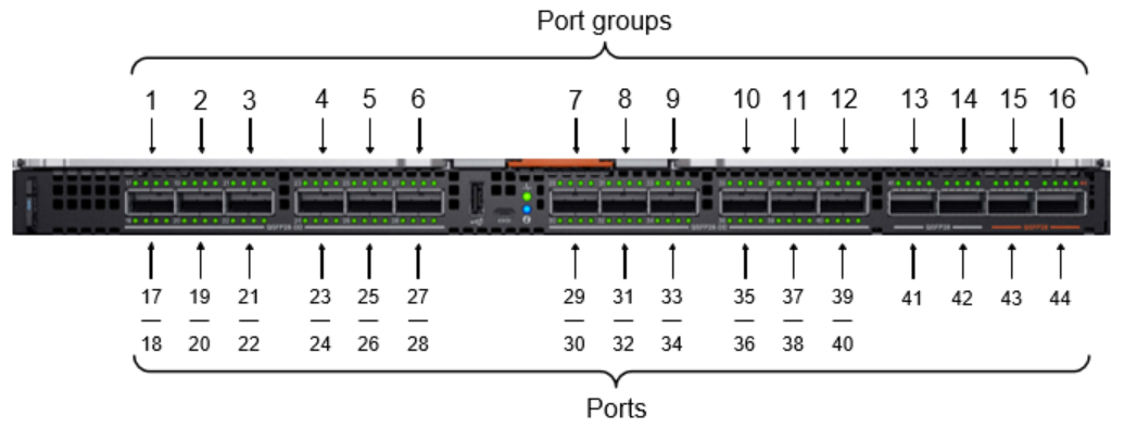
A port group is a logical port that consists of one or more physical ports and provides a single interface. Only the MX9116n FSE supports the following port groups:
- QSFP28-DD – Port groups 1 through 12
- QSFP28 – Port groups 13 and 14
- QSFP28 Unified – Port groups 15 and 16
The following figure shows these port groups along the top, and the bottom shows the physical ports in each port group. For instance, QSFP28-DD port group 1 has member ports 1/1/17 and 1/1/18, and unified port group 15 has a single member, port 1/1/43.
QSFP28-DD port groups
On the MX9116n FSE, QSFP28-DD port groups are 1 through 12, which contain ports 1/1/17 through 1/1/40 and are used to:
- Connect to a MX7116n FEM to extend the Scalable Fabric
- Connect to an Ethernet rack server or storage device
- Connect to another networking device, typically an Ethernet switch
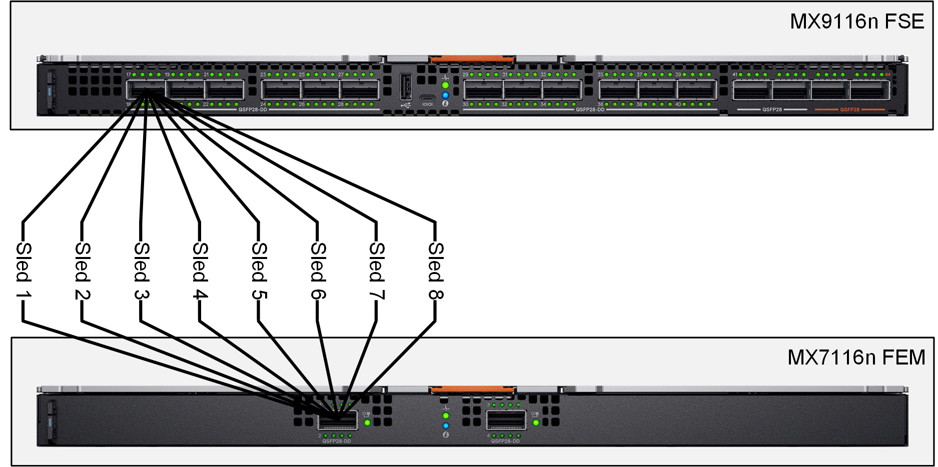
By default, QSFP28-DD port groups 1 through 9 are in fabric-expander-mode and QSFP28-DD port groups 10 through 12 are in 2x 100 GbE breakout mode. Fabric Expander mode is an 8x 25 GbE interface that is used only to connect to MX7116n FEMs in additional chassis. The interfaces from the MX7116n FEM appear as standard Ethernet interfaces from the perspective of the MX9116n FSE.
The following figure illustrates how the QSFP28-DD cable provides 8x 25 GbE lanes between the MX9116n FSE and a MX7116n FEM.
In addition to fabric-expander-mode, QSFP28-DD port groups support the following Ethernet breakout configurations:
- Using QSFP28-DD optics/cables:
- 2x 100 GbE – Breakout a QSFP28-DD port into two 100-GbE interfaces
- 2x 40 GbE – Breakout a QSFP28-DD port into two 40-GbE interfaces
- 8x 25 GbE – Breakout a QSFP28-DD port into eight 25-GbE interfaces
- 8x 10 GbE – Breakout a QSFP28-DD port into eight 10-GbE interfaces
- Using QSFP28 optics/cables:
- 1x 100 GbE – Breakout a QSFP28-DD port into one 100-GbE interface
- 4x 25 GbE – Breakout a QSFP28-DD port into four 25-GbE interfaces
- Using QSFP+ optics/cables:
- 1x 40 GbE – Breakout a QSFP28-DD port into one 40-GbE interface
- 4x 10 GbE – Breakout a QSFP28-DD port into four 10-GbE interfaces
Single-density QSFP28 port groups
On the MX9116n FSE, single-density QSFP28 port groups are 13 and 14, contain ports 1/1/41 and 1/1/42 respectively, and are used to connect to upstream networking devices. By default, both port groups are set to 1x 100 GbE. Port groups 13 and 14 support the following Ethernet breakout configurations:
- 4x 10 GbE – Breakout a QSFP28 port into four 10-GbE interfaces
- 1x 40 GbE – Set a QSFP28 port to 40 GbE mode
- 4x 25 GbE – Breakout a QSFP28 port into four 25-GbE interfaces
- 2x 50 GbE – Breakout a QSFP28 port into two 50-GbE interfaces
- 1x 100 GbE – Reset the unified port back to the default, 100-GbE mode
Unified port groups operate as either Ethernet or FC. By default, both unified port groups, 15 and 16, are set to 1x 100 GbE. To activate the two port groups as FC interfaces in Full Switch mode, use the command mode fc. Both port groups are enabled as Ethernet or FC together. You cannot have port group 15 as Ethernet and port group 16 as Fibre Channel.
The MX9116n FSE unified port groups support the following Ethernet breakout configurations:
- 4x 10 GbE – Breakout a QSFP28 port into four 10-GbE interfaces
- 1x 40 GbE – Set a QSFP28 port to 40 GbE mode
- 4x 25 GbE – Breakout a QSFP port into four 25-GbE interfaces
- 2x 50 GbE – Breakout a QSFP28 port into two 50-GbE interfaces
- 1x 100 GbE – Reset the unified port back to the default, 100-GbE mode
The MX9116n FSE unified port groups support the following FC breakout configurations:
- 4x 8 Gb – Breakout a unified port group into four 8-Gb FC interfaces
- 2x 16 Gb – Breakout a unified port group into two 16-Gb FC interfaces
- 4x 16 Gb – Breakout a unified port group into four 16-Gb FC interfaces
- 1x 32 Gb – Breakout a unified port group into one 32-Gb FC interface
- 2x 32 Gb – Breakout a unified port group into two 32-Gb FC interfaces
- 4x 32 Gb – Breakout a unified port group into four 32-Gb FC interfaces, rate limited
Rate limited 32 Gb Fibre Channel
When using 32-Gb FC, the actual data rate is 28 Gbps due to 64b/66b encoding. The following figure shows unified port group 15. The port group is set to 4x 32 Gb FC mode. However, each of the four lanes is 25 Gbps, not 28 Gbps. When these lanes are mapped from the Network Processing Unit (NPU) to the FC ASIC for conversion to FC signaling, the four 32 Gb FC interfaces are mapped to four 25 Gbps lanes. With each lane operating at 25 Gbps, not 28 Gbps, the result is rate limited to 25 Gbps.

While each 32 Gb FC connection is providing 25 Gbps, the overall FC bandwidth available is 100 Gbps per unified port group, or 200 Gbps for both ports. However, if an application requires the maximum 28 Gbps throughput per port, use the 2x 32 Gb breakout mode. This mode configures the connections between the NPU and the FC ASIC, as shown in the following figure.

In 2x 32 Gb FC breakout mode, the MX9116n FSE binds two 50 Gbps links together to provide a total of 100 Gbps bandwidth per lane to the FC ASIC. This results in the two FC ports operating at 28 Gbps. The overall FC bandwidth available is 56 Gbps per unified port, or 112 Gbps for both (compared to the 200 Gbps using 4x 32-Gb FC).
Virtual ports and slots
A virtual port is a logical interface that connects to a downstream server and has no physical location on the switch. Virtual ports are created when a MX9116n FSE onboards (discovers and configures) a MX7116n FEM.
If a MX7116n is moved and cabled to a different QSFP28-DD port on the MX9116n, all software configurations on the virtual ports are maintained. Only the QSFP28-DD breakout interfaces mapped to the virtual ports change.
A virtual slot contains all provisioned virtual ports across one or both FEM connections. On the MX9116n FSE, virtual slots 71 through 82 are pre-provisioned, and each virtual slot has eight virtual ports. For example, virtual slot 71 contains virtual ports ethernet 1/71/1 through 1/71/8. When a quad-port adapter is used, that virtual slot will expand to 16 virtual ports, for example ethernet 1/71/1 through 1/71/16.
If the MX9116n FSE is in SmartFabric mode, the MX7116n FEM is automatically configured with a virtual slot ID and virtual ports that are mapped to the physical interfaces. The following table shows how the physical ports are mapped to the virtual slot and ports.
If the MX9116n FSE is in Full Switch mode, it automatically discovers the MX7116n FEM when the following conditions are met:
- The MX7116n FEM is connected to the MX9116n FSE by attaching a Dell qualified cable between the QSFP28-DD ports on both devices.
- The interface for the QSFP28-DD port group connected to the MX9116n FSE is in 8x 25 GbE FEM mode.
- At least one blade server is inserted into the MX7000 chassis containing the MX7116n FEM.
The FEM will be automatically discovered and provisioned into a virtual slot when operating in SmartFabric mode. In Full Switch mode, this mapping is done with the unit-provision command. See show unit-provision for more information on the show unit-provision command.
To verify that a MX7116n FEM is communicating with the MX9116n FSE, enter the show discovered-expanders command.
MX9116n-FSE # show discovered-expanders
Service   Model          Type  Chassis      Chassis-slot Port-group Virtual
tag                            service-tag                          Slot-Id
--------------------------------------------------------------------------
D10DXC2 MX7116n FEM 1 SKY002Z A1 1/1/1| MX7116n service tag | MX9116n QSFP28-DD port group | MX9116n physical interface | MX7116n virtual slot (ID) | MX7116n virtual ports |
| 12AB3456 | portgroup1/1/1 | 1/1/17:1 | 71 | 1/71/1 |
| 1/1/17:2 | 1/71/2 | |||
| 1/1/17:3 | 1/71/3 | |||
| 1/1/17:4 | 1/71/4 | |||
| 1/1/18:1 | 1/71/5 | |||
| 1/1/18:2 | 1/71/6 | |||
| 1/1/18:3 | 1/71/7 | |||
| 1/1/18:4 | 1/71/8 |
Use the same command to show the list of MX7116n FEMs in a quad-port NIC configured scenario, in which each MX7116n FEM creates two connections with the MX9116n FSE. In a dual-chassis scenario, MX7116n FEMs are connected on port group 1 and port group 7 to the MX9116n FSE as shown below. For example, if the quad-port NIC is configured on compute sled 1, then virtual ports 1/1/71:1 and 1/1/71:9 will be up.
MX9116N-1# show discovered-expanders
Service   Model          Type  Chassis      Chassis-slot Port-group Virtual
tag                            service-tag                          Slot-Id
--------------------------------------------------------------------------
D10DXC2   MX7116n FEM    1     SKY002Z      A1           1/1/1      71
D10DXC2   MX7116n FEM    1     SKY002Z      A1           1/1/7      71
D10DXC4 MX7116n FEM 1 SKY003Z A1 1/1/2 72| MX7116n service tag | MX9116n QSFP28-DD port group | MX9116n physical interface | MX7116n virtual slot (ID) | MX7116n virtual ports |
| 12AB3456 | portgroup1/1/1 portgroup1/1/7 | 1/1/17:1 | 71 | 1/71/1 |
| 1/1/17:2 | 1/71/2 | |||
| 1/1/17:3 | 1/71/3 | |||
| 1/1/17:4 | 1/71/4 | |||
| 1/1/18:1 | 1/71/5 | |||
| 1/1/18:2 | 1/71/6 | |||
| 1/1/18:3 | 1/71/7 | |||
| 1/1/18:4 | 1/71/8 | |||
| 1/1/29:1 | 1/71/9 | |||
| 1/1/29:2 | 1/71/10 | |||
| 1/1/29:3 | 1/71/11 | |||
| 1/1/29:4 | 1/71/12 | |||
| 1/1/30:1 | 1/71/13 | |||
| 1/1/30:2 | 1/71/14 | |||
| 1/1/30:3 | 1/71/15 | |||
| 1/1/30:4 | 1/71/16 |
The MX9116n physical interfaces mapped to the MX7116n virtual ports display dormant (instead of up) in the show interface status output until a virtual port starts to transmit server traffic.
MX9116n-FSE # show interface status
Port         Description    Status    Speed    Duplex    Mode    Vlan
Eth 1/1/17:1                dormant
Eth 1/1/17:2                dormant
<output truncated>