
Compute server connectivity
Compute server connectivity
-
Compute server connectivity
Cisco UCS-X compute nodes, UCS B-Series blade servers, and Cisco UCS C-Series rack servers contain at least one physical Cisco UCS VIC for server connectivity.
- For Cisco UCS servers, the VIC passes converged FC and IP network traffic through the Cisco UCS 5108 blade server chassis midplane to the FEX.
- Cisco UCS C-Series rack servers can connect directly to each FI.
- Cisco UCS X9508 supports the Cisco UCS X210c M6 compute node.
Cisco UCS X9508 chassis connectivity
The Cisco UCS X9508 chassis contains Cisco UCS X210c M6 compute nodes and 14000-series VICs.
The following tables show the uplink connectivity from the Cisco X9508 chassis to the FI:
Table 23. Uplink connectivity from the Cisco X9508 chassis to the FI
Cisco UCS FI
Cisco UCS IFM
IFM uplink
Ethernet uplinks
Maximum chassis per domain
Cisco UCS 6454 FI
Cisco UCS 9108 25 G IFM
- 4
- 8
- 2
- 4
- 6
- 2
- 4
- 6
- 11
- 11
- 11
- 5
- 5
- 5
Cisco UCS 64108 FI
Cisco UCS 9108 25G IFM
- 4
- 8
- 2
- 4
- 6
- 2
- 4
- 6
- 16
- 20
- 20
- 8
- 16
- 20
Cisco UCS 6536 FI
Cisco UCS 9108 25G IFM
- 2
- 4
- 8
- 2
- 4
- 6
- 8
- 2
- 4
- 6
- 8
- 2
- 4
- 6
- 8
- 8
- 14
- 13
- 12
- 4
- 7
- 6
- 6
- 2
- 3
- 3
- 3
Cisco UCS C-Series rack server direct connect mode
Directly connecting rackmount servers to the FIs lets Cisco Intersight manage the Cisco UCS C-Series rack servers using a single cable for both management and data traffic. The Cisco UCS VIC connects to the FI using a single connection from each VIC to each FI. This method is used for configurations that require fewer servers.
Different generations of VICs are not supported in a single server. Use the Cisco UCS VIC 14xx or 15xxx series. These servers include the following features:
- 4th-generation Cisco UCS C-Series rack servers with:
- 25 Gbps per fabric on the Cisco UCS VIC 15428 or 1467 mLOMs and a 1455 PCIe on Cisco UCSM6 servers.
- Cisco UCS VIC 15428, 1467, and 1455 Small Form-Factor Pluggable (SFP28) cards for the M6 servers. These cards support 10/25-Gbps Ethernet or FCoE.
- Cisco UCS C-Series rack server Direct Connect license.
- 5th-generation Cisco UCS C-Series rack servers in Direct Connect mode with:
- 100 Gbps per fabric on a Cisco UCS VIC 15238 or 1477 mLOMs and a 1495 PCIe on Cisco UCS M6 servers.
- The Cisco UCS VIC 15238, 1477, and 1495 are dual-port Quad Small Form-Factor (QSFP28) mLOM cards for the M6 servers. These cards support 40/100-Gbps Ethernet or FCoE.
The following table shows the port-to-FI connections on the Cisco UCS VICs:
Table 24. Cisco UCS VIC port connections
Cisco UCS VIC
Connections
1455
1467
1477
Ports 1 and 2 are in one port group and connect to FI A.
Ports 3 and 4 are in the other port group and connect to FI B.
Single-link connectivity:
1477
15238
Port 1 or 2 connects to FI A and port 3 or 4 connects to FI B.
Dual-link connectivity:
1455
1467
Ports 1 and 2 connect to FI A.
Ports 3 and 4 connect to FI B
Note: Cisco UCS FIs support dual-link connectivity.
Cisco UCS mixed server configuration
Cisco UCS has a unique architecture that integrates compute, data network, and storage network access into a common set of components under a single management interface.
Cisco UCS fuses access layer networking and servers. The hardware and software components support the Cisco UCS unified fabric, which runs multiple types of data center traffic over a single converged network adapter. When switching is not used in a Cisco UCS X9508 chassis, network access-layer fragmentation is reduced. All devices in a Cisco UCS domain remain under a single management domain, which uses redundant components to remain highly available.
The following figure shows a mixed server configuration for Cisco UCS B-Series blade servers and Cisco UCS C-Series rack servers:
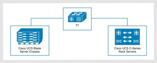
Figure 6. Cisco UCS mixed server configuration: B-Series blade servers and C-Series rack servers
Fabric interconnect oversubscription
The following figure shows a mixed-server configuration with the Cisco UCS X9508 compute node chassis and Cisco UCS C-Series rack servers:
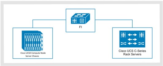
Figure 7. Cisco UCS mixed-server configuration example: X9508 compute node chassis and C-Series rack servers
For optimal performance, keep all compute domains at an oversubscription rate of 8:1 or lower, The 8 in this ratio is the committed host bandwidth as well as the Ethernet uplinks, while the 1 is for the FC uplinks
The following table shows an example of a 5108 chassis with 4-link and 8-link 25G connections to the FI. The FI shows 2, 4, or 6 uplink options from a 6454 FI to a 9336C ToR switch. The area that is marked in red is oversubscribed. The 11 chassis with 8 links per side provide 2,200 GB or bandwidth to the FI per side compared with 2 uplinks to the ToR, providing only 200 GB of bandwidth. That yields 2.200 ÷200 = 11. To avoid oversubscription, provide 4-upinks from the 6454 FI to the 9336C ToR switch, as shown in the table.
Table 25. Cisco UCS 5108 chassis with 4-link and 8-link 25G connections to the FI (example)
B-Series
QTY
Total bandwidth used per side
Oversubscription rates per side on the 6454 FI (8:1 ratio)
1 domain
2-uplinks (200 GB)
4-uplinks (400 GB)
6-uplinks (600 GB)
Chassis IOM with 4-Links 25 G
20 chassis (80 servers)
2 TB
10:1
5:1
3.3:1
Chassis IOM with 8-Links 25 G
11 chassis (88 servers)
2.2 TB
11:1
5.5:1
3.6:1
Chassis IOM with 8-Links 25 G
10 chassis (80 servers)
2 TB
10:1
5:1
3.3:1
When planning your environment, use the guidance in the preceding table to ensure that you do not oversubscribe on Ethernet or FC connections.
Disjoint Layer 2 configuration
In a Disjoint Layer 2 configuration, traffic is split between two or more networks at the FI to support two or more discrete Ethernet clouds.
Disjoint Layer 2 on the FI must be configured on ports that are not used for the standard LAN uplink traffic.
On the 4th-generation Cisco UCS 6454 or 64108 FIs, the network ports are:
- Non-FC 10 Gbps or 25 Gbps unified ports
- 40 Gb or 100 GbE Uplink ports
Cisco UCS servers connect to different Ethernet clouds that otherwise never connect. Upstream Disjoint Layer 2 networks give access to the cloud to servers or VMs that are located in the same Cisco UCS domain.
The following figure shows an example of Disjoint Layer 2 networking into a Cisco UCS domain:
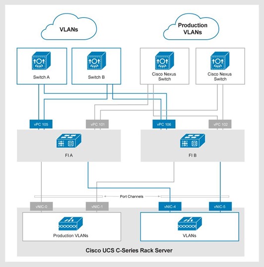
Figiure 8. Disjoint Layer 2 networking into a Cisco UCS domain
The 101 and 102 vPCs uplinks are production uplinks that connect to the network layer of the 3-Tier Platform. vPCs 105 and 106 are external uplinks that connect to other switches.
Disjoint Layer 2 network connectivity are also configurable with an individual uplink on each FI.
Supported cabling in an Intersight domain
The following tables provide information about supported cabling on the specified FIs:
Table 26. Cisco UCS 6454 FIs
Source equipment
Destination
Connection type
SFP/cable type
Ports
Cisco UCS 6454 FI
Cisco Nexus 9336C
Ethernet Uplink
100G AOC cables (domains 1 and 2)
QSFP-40G/100G-SRBD or QSFP-100G-SR4-S (domains 3 to 7)
49 to 54
Cisco UCS 6454 FI
Cisco MDS 9148T, 9396T, 9706-v2 and 9710-v2
FC uplink
DS-SFP-FC32G-SW with LC-LC FC Cable
1 to 16
Cisco UCS 6454 FI
Cisco UCS 5108 chassis w/ B200 M6 blade servers
Cisco C220 and C240 M6 Rackmount Servers
Server
25G Twinax (SFP-H25G-CUxM)
SFP-25G-SR-S with LC-LC FC cable
Note: The “x” in SFP-H25G-CUxM is the length of the cable.
5 to 48, 9 to 48, or 17 to 48 depending on how many FC uplinks are used.
Table 27. Cisco UCS 64108 FIs
Source equipment
Destination
Connection type
SFP/cable type
Ports
Cisco UCS 64108 FI
Cisco Nexus 9336C
Ethernet uplink
100G AOC cables (domains 1 and 2)
QSFP-40G/100G-SRBD or QSFP-100G-SR4-S (domains 3 to 7)
97–108
Cisco UCS 64108 FI
Cisco MDS 9148T, 9396T, 9706-v2 and 9710-v2
FC uplink
DS-SFP-FC32G-SW with LC-LC FC cable
1 to16
Cisco UCS 64108 FI
Cisco UCS 5108 chassis w/ B200 M6 blade servers
Cisco C220 and C240 M6 rackmount servers
Server
25G Twinax (SFP-H25G-CUxM)
SFP-25G-SR-S with LC-LC FC cableNote: The “x” in SFP-H25G-CUxM is the length of the cable.
9 to 96 or 17 to 96 depending on how many FC uplinks are used.
Table 28. 6536 Cisco UCS FIs
Source equipment
Destination
Connection type
Sfp/cable type
Ports
Cisco UCS 6536 FI
Cisco Nexus 9336C
Ethernet uplink
100G AOC Cables (domains 1 and 2)
QSFP-40G/100G-SRBD or QSFP-100G-SR4-S (domains 3 to 7)25 to 32
Cisco UCS 6536 FI
Cisco MDS 9148T, 396T, 9706-v2 and 9710-v2
FC uplink
DS-SFP-4X32G-SW
Multimode OM4 MPO female to 4x LC type-B breakout cable
33 to 36 (FC breakout ports)
Cisco UCS 6536 FI
Cisco UCS 5108 chassis w/ B200 M6 blade servers
Cisco UCS X9508 chassis w/ x210c compute nodes
Cisco C220 and C240 M6 rackmount servers
Server
100G Twinax (QSFP-100G-CUxM)
100G AOC (QSFP-100G-AOCxM)
QSFP-100G-SR4-S with MPO OM4 Multimode Fiber
Note: The “x” in QSFP-100G-CU3M and QSFP-100G-AOCxM is the length of the cable.
1 to 24 or 1 to 30 depending on how many FC and Ethernet uplinks are used.
For more information about supported cabling on the specified FIs, see: