


Dell Technologies Direct Liquid Cooling Support for New PowerEdge Servers
Download PDFMon, 16 Jan 2023 13:44:21 -0000
|Read Time: 0 minutes
Summary
Liquid cooling is a very effective method of capturing heat commonly produced by semi- conductors, such as processors and memory, and transferring it to an isolated region to dissipate. For the release of the new Intel and AMD-based PowerEdge servers, Dell Technologies is offering a direct liquid cooling solution to ensure that customer cooling needs are met. This DfD will educate readers on how the Dell Technologies direct liquid cooling solution works, which PowerEdge servers support them, and why this solution is advantageous for data centers.
Introduction
New 15G PowerEdge platforms will offer CPUs with higher power than ever before. Dell is introducing new Direct Liquid Cooling (DLC) solutions to effectively manage these growing thermal challenges. Dell DLC solutions cool the CPU with warm liquid which has much greater (~4x) heat capacity versus air. Thus, DLC is a higher performance cooling solution for managing the CPU temperature while also enabling higher performance and better reliability. Because DLC solutions are more efficient at extracting heat, this reduces the burden on server system fans as well as the data center’s cooling infrastructure, improving sustainability and saving customers money.
New PowerEdge Server Support
Dell is expanding our portfolio of platforms with factory-installed DLC solution, from dense compute C-series to our 1U and 2U rack-mount servers. The PowerEdge servers below offer DLC cooling on the newest Intel and AMD processors:
- C6520
- C6525
- R6525
- R7525
- R650
- R750
- R750XA
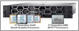
Figure 1 - Multiple PowerEdge servers with new Intel and AMD processors will support the Dell Technologies DLC
Direct Liquid Cooling Technology
DLC uses the exceptional thermal capacity of liquid to absorb and remove heat created by new high-power processors. Cold plates are attached directly to the processors (see Figure 2), and then coolant captures and removes the heat from the system to a heat exchanger located in the rack or row. This heat load is removed from the datacenter via a warm water loop, potentially bypassing the expensive chiller system. By replacing (or supplementing) conventional air-cooling with higher-efficient liquid cooling, the overall operational efficiency of the data center is improved.
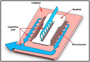
Figure 2 - DLC example of a cold plate and coolant loop
New Features and Solutions
Leaking Sensing Technology
Leak Sense technology is a new feature now included with all Dell DLC solutions, providing customers with the knowledge that potential issues will be found and reported quickly. If a coolant leak occurs, the system’s leak sensor will log an alert in the iDRAC system. Three errors can be reported: small leak (warning), large leak (critical), leak sensor error (warning – indicates the issue with the leak detection board). These error detections can be configured to take meaningful actions, such as raise an alert or power-off a server.
POD Solution
Whereas a node-level DLC solution captures between 50%-60% of a server’s internal heat (depending on the configuration), the Dell Technologies rack-level POD solution concept is designed for total heat capture. The POD solution contains front and back containment for racks of DLC servers, plus an InRow Cooler integrated between the IT racks to capture any remaining heat. Figure 3 illustrates a POD solution example.
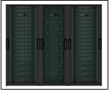
Figure 3 - Pod solution containing two outer racks with node-level DLC and one middle InRow Cooler
Benefits of Liquid Cooling Implementation
- Increased System Cooling Capacity – DLC enables system configurations that may not possible with air cooling alone, such as high TDP CPUs, dense storage and/or add-in cards.
- Improved Energy Efficiency (PUE) – The DLC cold plate solution reduces energy costs by up to 45% relative to cooled air 1, and helps extend the life of existing air infrastructure
- Higher Compute Density – For the Ice Lake based C6520 system, DLC cooling supports of up to 25% more cores per rack. For the Milan based C6525 system (with backplane configuration supporting storage drives), DLC cooling enables 2x the core count over air-cooling alone.
- 3.1x ROI Within 4 Years – The cost of pairing DLC with existing PowerEdge cooling tower infrastructure typically breaks even within 1.3 years and yields a 3.1x payback within 4 years 2
- Swift Serviceability – The CPU DLC cold plate solution attaches with four screws, making service quick and simple.
Conclusion
The Dell Technologies DLC solution enables PowerEdge server components to take on dense workloads while staying within their required thermal limits. Customers can maximize the utilization of their datacenters with confidence knowing they have the best efficiency, ROI and flexibility that a thermal design has to offer.
- Based on Dell EMC internal analysis, March 2021, comparing hypothetical air-cooled data center with a cooling PUE of 0.62 to a hybrid data center with a cooling PUE of 0.34. A PUE of 0.21 was assigned to all overhead not attributed to cooling. Operating costs and other factors will cause results to vary. RS Means industry standards cost basis was used to measure typical cooling infrastructure costs and determine projected savings.
- Based on Dell EMC internal analysis, March 2021 comparing a hypothetical air-cooled data center to a hybrid data center. Assuming 1244 nodes, the air cooled data center uses 1825 kW whereas the hybrid uses 1544 kW. Individual operating costs and other factors will vary the results. RS Means industry standards cost basis was used to measure typical cooling infrastructure costs and determine projected savings. Based on Dell EMC internal analysis, calculating the capital cost of DLC minus the amount of CRAH, pumps, chiller, and tower to equal the net cost of DLC, and examining the operational costs of a hypothetical air-cooled data center and a hybrid data center to determine ROI. Assumes a high wattage CPU. Schneider Electric developed an analytical model that ascribes operating costs to the various types of facility infrastructure equipment. Electricity costs and other factors will vary the results. RS Means industry standards cost basis was used to estimate cooling infrastructure costs and determine projected savings.
Related Documents
The Future of Server Cooling - Part 2: New IT hardware Features and Power Trends

Fri, 03 Mar 2023 17:21:25 -0000
|Read Time: 0 minutes
Summary
Part 1 of this three-part series, titled The Future of Server Cooling, covered the history of server and data center cooling technologies.
Part 2 of this series covers new IT hardware features and power trends with an overview of the cooling solutions that Dell Technologies provides to keep IT infrastructure cool.
Overview
The Future of Server Cooling was written because future generations of PowerEdge servers may require liquid cooling to enable certain CPU or GPU configurations. Our intent is to educate customers about why the transition to liquid cooling may be required, and to prepare them ahead of time for these changes. Integrating liquid cooling solutions on future PowerEdge servers will allow for significant performance gains from new technologies, such as next-generation Intel® Xeon® and AMD EPYC CPUs, and NVIDIA, Intel, and AMD GPUs, as well as the emerging segment of DPUs.
Part 1 of this three-part series reviewed some major historical cooling milestones and evolution of cooling technologies over time both in the server and the data center.
Part 2 of this series describes the power and cooling trends in the server industry and Dell Technologies’ response to the challenges through intelligent hardware design and technology innovation.
Part 3 of this series will focus on technical details aimed to enable customers to prepare for the introduction, optimization, and evolution of these technologies within their current and future datacenters.
Increasing power requirements and heat generation trends within servers
CPU TDP trends over time – Over the past ten years, significant innovations in CPU design have included increased core counts, advancements in frequency management, and performance optimizations. As a result, CPU Thermal Design Power (TDP) has nearly doubled over just a few processor generations and is expected to continue increasing.
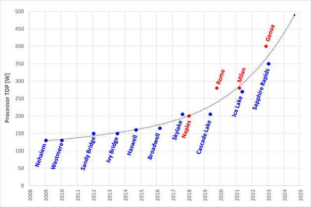
Figure 1. TDP trends over time
Emergence of GPUs – Workloads such as Artificial Intelligence (AI) and Machine Learning (ML) capitalize the parallel processing capabilities of Graphic Processing Units (GPUs). These subsystems require significant power and generate significant amounts of heat. As it has for CPUs, the power consumption of GPUs has rapidly increased. For example, while the power of an NVIDIA A100 GPU in 2021 was 300W, NVIDIA H100 GPUs are releasing soon at up to 700W. GPUs up to 1000W are expected in the next three years.
Memory – As CPU capabilities have increased, memory subsystems have also evolved to provide increased performance and density. A 128GB LRDIMM installed in an Intel-based Dell 14G server would operate at 2666MT/s and could require up to 11.5W per DIMM. The addition of 256GB LRDIMMs for subsequent Dell AMD platforms pushed the performance to 3200MT/s but required up to 14.5W per DIMM. The latest Intel and AMD based platforms from Dell operate at 4800MT/s and with 256GB RDIMMs consuming 19.2W each. Intel based systems can support up to 32 DIMMs, which could require over 600W of power for the memory subsystem alone.
Storage – Data storage is a key driver of power and cooling. Fewer than ten years ago, a 2U server could only support up to 16 2.5” hard drives. Today a 2U server can support up to 24 2.5” drives. In addition to the increased power and cooling that this trend has driven, these higher drive counts have resulted in significant air flow impedance both on the inlet side and exhaust side of the system. With the latest generation of PowerEdge servers, a new form factor called E3 (also known as EDSFF or “Enterprise & Data Center SSD Form Factor) brings the drive count to 16 in some models but reduces the width and height of the storage device, which gives more space for airflow. The “E3” family of devices includes “Short” (E3.S), “Short – Double Thickness”: (E3.S 2T), “Long” (E3.L), and “Long – Double Thickness” (E3L.2T). While traditional 2.5” SAS drives can require up to 25W, these new EDSFF designs can require up to 70W as shown in the following table.
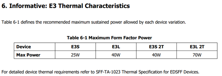
(Source: https://members.snia.org/document/dl/26716, page 25.)
Innovative Dell Technologies design elements and cooling techniques to help manage these trends
“Smart Flow” configurations
Dell ISG engineering teams have architected new system storage configurations to allow increased system airflow for high power configurations. These high flow configurations are referred to as “Smart Flow”. The high airflow aspect of Smart Flow is achieved using new low impedance airflow paths, new storage backplane ingredients, and optimized mechanical structures all tuned to provide up to a 15% higher airflow compared to traditional designs. Smart Flow configurations allow Dell’s latest generation of 1U and 2U servers to support new high-power CPUs, DDR5 DIMMs, and GPUs with minimal tradeoffs.

Figure 2. R660 “Smart Flow” chassis
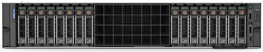
Figure 3. R760 “Smart Flow” chassis
FGPU configurations
The R750xa and R760xa continue the legacy of the Dell C4140, with GPUs located in the “first-class” seats at the front of the system. Dell thermal and system architecture teams designed these next generation GPU optimized systems with GPUs in the front to provide fresh (non-preheated) air to the GPUs in the front of the system. These systems also incorporate larger 60x76mm fans to provide the high airflow rates required by the GPUs and CPUs in the system. Look for additional fresh air GPU architectures in future Dell systems.
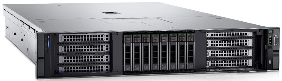
Figure 4. R760xa chassis showing “first class seats” for GPU at the front of the system
4th Generation DLC with leak detection
Dell’s latest generation of servers continue to expand on an already extensive support for direct liquid cooling (DLC). In fact, a total of 12 Dell platforms have a DLC option including an all-new offering of DLC in the MX760c. Dell’s 4th generation liquid cooling solution has been designed for robust operation under the most extreme conditions. If an excursion occurs, Dell has you covered. All platforms supporting DLC utilize Dell’s proprietary Leak Sensor solution. This solution is capable of detecting and differentiating small and large leaks which can be associated with configurable actions including email notification, event logging, and system shutdown.
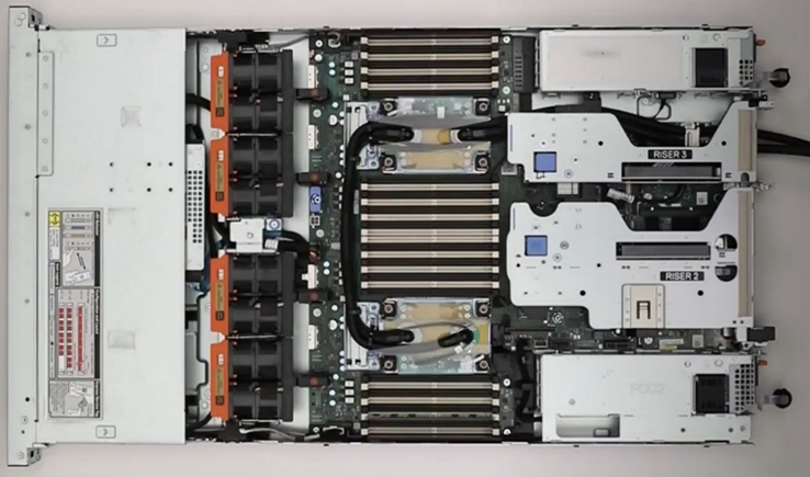
Figure 5. 2U chassis with Direct Liquid Cooling heatsink and tubing
Application optimized designs
Dell closely monitors not only the hardware configurations that customers choose but also the application environments they run on them. This information is used to determine when design changes might help customers to achieve a more efficient design for power and cooling with various workloads.
An example of this is in the Smart Flow designs discussed previously, in which engineers reduced the maximum storage potential of the designs to deliver more efficient air flow in configurations that do not require maximum storage expansion.
Another example is in the design of the “xs” (R650xs, R660xs, R750xs, and R760xs) platforms. These platforms are designed to be optimized specifically for virtualized environments. Using the R750xs as an example, it supports a maximum of 16 hard drives. This reduces the density of power supplies that must be supported and allows for the use of lower cost fans. This design supports a maximum of 16 DIMMs which means that the system can be optimized for a lower maximum power threshold, yet still deliver enough capacity to support large numbers of virtual machines. Dell also recognized that the licensing structure of VMware supports a maximum of 32 cores per license. This created an opportunity to reduce the power and cooling loads even further by supporting CPUs with a maximum of 32 cores which have a lower TDP than the higher core count CPUs.
Software design
As power and cooling requirements increase, Dell is also investing in software controls to help customers manage these new environments. iDRAC and Open Manage Enterprise (OME) with the Power Manager plug-in both provide power capping. OME Power Manager will automatically manipulate power based on policies set by the customer. In addition, iDRAC, OME Power Manager, and CloudIQ all report power usage to allow the customer the flexibility to monitor and adapt power usage based on their unique requirements.
Conclusion
As Server technology evolves, power and cooling challenges will continue. Fan power in air-cooled servers is one of largest contributors to wasted power. Minimizing fan power for typical operating conditions is the key to a thermally efficient server and has a large impact on customer sustainability footprint.
As the industry adopts liquid cooling solutions, Dell is ensuring that air cooling potentials are maximized to protect customer infrastructure investments in air cooling based data centers around the globe. The latest generation of Dell servers required advanced engineering simulations and analysis to improve system design to increase system airflow per unit watt of fan power, as compared to the previous generation of platforms, not only to maximize air cooling potential but to keep it efficient as well. Additional air-cooling opportunities are enabled with Smart Flow configurations – allowing higher CPU bins to be air cooled, as compared to the requirement for liquid cooling. A large number of thermal and power sensors have been implemented to manage both power and thermal transients using Dell proprietary adaptive closed loop algorithms that maximize cooling at the lowest fan power state and that protect systems at excursion conditions by closed loop power management.
Understanding the Value of AMDs Socket to Socket Infinity Fabric
Tue, 17 Jan 2023 00:43:22 -0000
|Read Time: 0 minutes
Summary
AMD socket-to-socket Infinity Fabric increases CPU-to-CPU transactional speeds by allowing multiple sockets to communicate directly to one another through these dedicated lanes. This DfD will explain what the socket-to-socket Infinity Fabric interconnect is, how it functions and provides value, as well as how users can gain additional value by dedicating one of the x16 lanes to be used as a PCIe bus for NVMe or GPU use.
Introduction
Prior to socket-to-socket Infinity Fabric (IF) interconnect, CPU-to-CPU communications generally took place on the HyperTransport (HT) bus for AMD platforms. Using this pathway for multi-socket servers worked well during the lifespan of HT, but developing technologies pushed for the development of a solution that would increase data transfer speeds, as well as allow for combo links.
AMD released socket-to-socket Infinity Fabric (also known as xGMI) to resolve these bottlenecks. Having dedicated IF links for direct CPU-to- CPU communications allowed for greater data-transfer speeds, so multi-socket server users could do more work in the same amount of time as before.
How Socket-to-Socket Infinity Fabric Works
IF is the external socket-to-socket interface for 2-socket servers. The architecture used for IF links is a combo of serializer/deserializer (SERDES) that can be both PCIe and xGMI, allowing for sixteen lanes per link and a lot of platform flexibility. xGMI2 is the current generation available and it has speeds that reach up to 18Gbps; which is faster than the PCIe Gen4 speed of 16Gbps. Two CPUs can be supported by these IF links. Each IF lane connects from one CPU IO die to the next, and they are interwoven in a similar fashion, directly connecting the CPUs to one- another. Most dual-socket servers have three to four IF links dedicated for CPU connections. Figure 1 depicts a high- level illustration of how socket to socket IF links connect across CPUs.
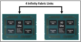
Figure 1 – 4 socket to socket IF links connect two CPUs
The Value of Infinity Fabric Interconnect
Socket to socket IF interconnect creates several advantages for PowerEdge customers:
- Dedicated IF lanes are routed directly from one CPU to the other CPU, ensuring inter-socket communications travel the shortest distance possible
- xGMI2 speeds (18Gbps) exceed the speeds of PCIe Gen4, allowing for extremely fast inter-socket data transfer speeds
Furthermore, if customers require additional PCIe lanes for peripheral components, such as NVMe or GPU drives, one of the four IF links are a cable with a connector that can be repurposed as a PCIe lane. AMD’s highly optimized and flexible link topologies enable sixteen lanes per socket of Infinity Fabric to be repurposed. This means that 2S AMD servers, such as the PowerEdge R7525, have thirty-two additional lanes giving a total of 160 PCIe lanes for peripherals. Figure 2 below illustrates what this would look like:
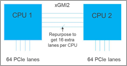
Figure 2 – Diagram showing additional PCIe lanes available in a 2S configuration
Conclusion
AMDs socket-to-socket Infinity Fabric interconnect replaced the former HyperTransport interconnect in order to allow massive amounts of data to travel fast enough to avoid speed bottlenecks. Furthermore, customers needing additional PCIe lanes can repurpose one of the four IF links for peripheral support. These advantages allow AMD PowerEdge servers, such as the R7525, to meet our server customer needs.