


The Future of Server Cooling - Part 2: New IT hardware Features and Power Trends
Download PDF
Summary
Part 1 of this three-part series, titled The Future of Server Cooling, covered the history of server and data center cooling technologies.
Part 2 of this series covers new IT hardware features and power trends with an overview of the cooling solutions that Dell Technologies provides to keep IT infrastructure cool.
Overview
The Future of Server Cooling was written because future generations of PowerEdge servers may require liquid cooling to enable certain CPU or GPU configurations. Our intent is to educate customers about why the transition to liquid cooling may be required, and to prepare them ahead of time for these changes. Integrating liquid cooling solutions on future PowerEdge servers will allow for significant performance gains from new technologies, such as next-generation Intel® Xeon® and AMD EPYC CPUs, and NVIDIA, Intel, and AMD GPUs, as well as the emerging segment of DPUs.
Part 1 of this three-part series reviewed some major historical cooling milestones and evolution of cooling technologies over time both in the server and the data center.
Part 2 of this series describes the power and cooling trends in the server industry and Dell Technologies’ response to the challenges through intelligent hardware design and technology innovation.
Part 3 of this series will focus on technical details aimed to enable customers to prepare for the introduction, optimization, and evolution of these technologies within their current and future datacenters.
Increasing power requirements and heat generation trends within servers
CPU TDP trends over time – Over the past ten years, significant innovations in CPU design have included increased core counts, advancements in frequency management, and performance optimizations. As a result, CPU Thermal Design Power (TDP) has nearly doubled over just a few processor generations and is expected to continue increasing.
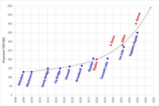
Figure 1. TDP trends over time
Emergence of GPUs – Workloads such as Artificial Intelligence (AI) and Machine Learning (ML) capitalize the parallel processing capabilities of Graphic Processing Units (GPUs). These subsystems require significant power and generate significant amounts of heat. As it has for CPUs, the power consumption of GPUs has rapidly increased. For example, while the power of an NVIDIA A100 GPU in 2021 was 300W, NVIDIA H100 GPUs are releasing soon at up to 700W. GPUs up to 1000W are expected in the next three years.
Memory – As CPU capabilities have increased, memory subsystems have also evolved to provide increased performance and density. A 128GB LRDIMM installed in an Intel-based Dell 14G server would operate at 2666MT/s and could require up to 11.5W per DIMM. The addition of 256GB LRDIMMs for subsequent Dell AMD platforms pushed the performance to 3200MT/s but required up to 14.5W per DIMM. The latest Intel and AMD based platforms from Dell operate at 4800MT/s and with 256GB RDIMMs consuming 19.2W each. Intel based systems can support up to 32 DIMMs, which could require over 600W of power for the memory subsystem alone.
Storage – Data storage is a key driver of power and cooling. Fewer than ten years ago, a 2U server could only support up to 16 2.5” hard drives. Today a 2U server can support up to 24 2.5” drives. In addition to the increased power and cooling that this trend has driven, these higher drive counts have resulted in significant air flow impedance both on the inlet side and exhaust side of the system. With the latest generation of PowerEdge servers, a new form factor called E3 (also known as EDSFF or “Enterprise & Data Center SSD Form Factor) brings the drive count to 16 in some models but reduces the width and height of the storage device, which gives more space for airflow. The “E3” family of devices includes “Short” (E3.S), “Short – Double Thickness”: (E3.S 2T), “Long” (E3.L), and “Long – Double Thickness” (E3L.2T). While traditional 2.5” SAS drives can require up to 25W, these new EDSFF designs can require up to 70W as shown in the following table.
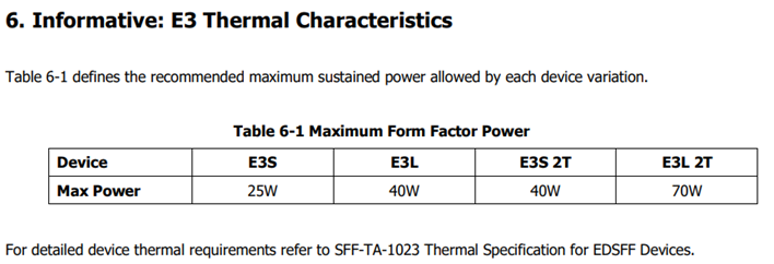
(Source: https://members.snia.org/document/dl/26716, page 25.)
Innovative Dell Technologies design elements and cooling techniques to help manage these trends
“Smart Flow” configurations
Dell ISG engineering teams have architected new system storage configurations to allow increased system airflow for high power configurations. These high flow configurations are referred to as “Smart Flow”. The high airflow aspect of Smart Flow is achieved using new low impedance airflow paths, new storage backplane ingredients, and optimized mechanical structures all tuned to provide up to a 15% higher airflow compared to traditional designs. Smart Flow configurations allow Dell’s latest generation of 1U and 2U servers to support new high-power CPUs, DDR5 DIMMs, and GPUs with minimal tradeoffs.

Figure 2. R660 “Smart Flow” chassis
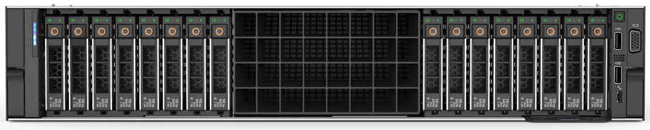
Figure 3. R760 “Smart Flow” chassis
FGPU configurations
The R750xa and R760xa continue the legacy of the Dell C4140, with GPUs located in the “first-class” seats at the front of the system. Dell thermal and system architecture teams designed these next generation GPU optimized systems with GPUs in the front to provide fresh (non-preheated) air to the GPUs in the front of the system. These systems also incorporate larger 60x76mm fans to provide the high airflow rates required by the GPUs and CPUs in the system. Look for additional fresh air GPU architectures in future Dell systems.
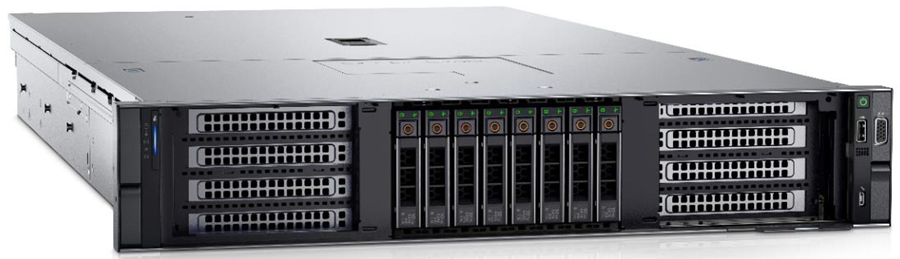
Figure 4. R760xa chassis showing “first class seats” for GPU at the front of the system
4th Generation DLC with leak detection
Dell’s latest generation of servers continue to expand on an already extensive support for direct liquid cooling (DLC). In fact, a total of 12 Dell platforms have a DLC option including an all-new offering of DLC in the MX760c. Dell’s 4th generation liquid cooling solution has been designed for robust operation under the most extreme conditions. If an excursion occurs, Dell has you covered. All platforms supporting DLC utilize Dell’s proprietary Leak Sensor solution. This solution is capable of detecting and differentiating small and large leaks which can be associated with configurable actions including email notification, event logging, and system shutdown.
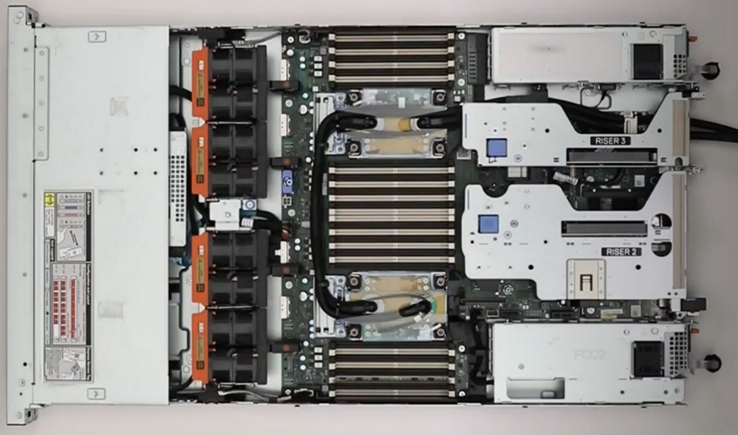
Figure 5. 2U chassis with Direct Liquid Cooling heatsink and tubing
Application optimized designs
Dell closely monitors not only the hardware configurations that customers choose but also the application environments they run on them. This information is used to determine when design changes might help customers to achieve a more efficient design for power and cooling with various workloads.
An example of this is in the Smart Flow designs discussed previously, in which engineers reduced the maximum storage potential of the designs to deliver more efficient air flow in configurations that do not require maximum storage expansion.
Another example is in the design of the “xs” (R650xs, R660xs, R750xs, and R760xs) platforms. These platforms are designed to be optimized specifically for virtualized environments. Using the R750xs as an example, it supports a maximum of 16 hard drives. This reduces the density of power supplies that must be supported and allows for the use of lower cost fans. This design supports a maximum of 16 DIMMs which means that the system can be optimized for a lower maximum power threshold, yet still deliver enough capacity to support large numbers of virtual machines. Dell also recognized that the licensing structure of VMware supports a maximum of 32 cores per license. This created an opportunity to reduce the power and cooling loads even further by supporting CPUs with a maximum of 32 cores which have a lower TDP than the higher core count CPUs.
Software design
As power and cooling requirements increase, Dell is also investing in software controls to help customers manage these new environments. iDRAC and Open Manage Enterprise (OME) with the Power Manager plug-in both provide power capping. OME Power Manager will automatically manipulate power based on policies set by the customer. In addition, iDRAC, OME Power Manager, and CloudIQ all report power usage to allow the customer the flexibility to monitor and adapt power usage based on their unique requirements.
Conclusion
As Server technology evolves, power and cooling challenges will continue. Fan power in air-cooled servers is one of largest contributors to wasted power. Minimizing fan power for typical operating conditions is the key to a thermally efficient server and has a large impact on customer sustainability footprint.
As the industry adopts liquid cooling solutions, Dell is ensuring that air cooling potentials are maximized to protect customer infrastructure investments in air cooling based data centers around the globe. The latest generation of Dell servers required advanced engineering simulations and analysis to improve system design to increase system airflow per unit watt of fan power, as compared to the previous generation of platforms, not only to maximize air cooling potential but to keep it efficient as well. Additional air-cooling opportunities are enabled with Smart Flow configurations – allowing higher CPU bins to be air cooled, as compared to the requirement for liquid cooling. A large number of thermal and power sensors have been implemented to manage both power and thermal transients using Dell proprietary adaptive closed loop algorithms that maximize cooling at the lowest fan power state and that protect systems at excursion conditions by closed loop power management.
Related Documents

The Future of Server Cooling- Part 1. The History of Server and Data Center Cooling Technologies
Mon, 16 Jan 2023 18:15:45 -0000
|Read Time: 0 minutes
Summary
Today’s servers require more power than ever before. While this spike in power has led to more capable servers, it has coincidentally pushed legacy thermal hardware to its limit. The inability to support top- performance servers without liquid cooling will soon become an industry-wide challenge. We hope that by preparing our PowerEdge customers for this transition ahead of time, and explaining in detail why and when liquid cooling is necessary, they can easily adapt and get excited for the performance gains liquid cooling will enable.
Part 1 of this three part series, titled The Future of Server Cooling, covers the history of server and data center thermal technologies - which cooling methods are most commonly used, and how they evolved to enable the industry growth seen today.
The Future of Server Cooling was written because the next-generation of PowerEdge servers (and succeeding generations) may require liquid cooling assistance to enable certain (dense) configurations. Our intent is to educate customers about why the transition to liquid cooling is inevitable, and to prepare them for these changes.
Integrating liquid cooling solutions on future PowerEdge servers will allow for significant performance gains from new technologies, such as next-generation Intel® Xeon® and AMD EPYC™ CPUs, DDR5 memory, PCIe Gen5, DPUs, and more.
Part 1 of this three part series reviews some major historical cooling milestones to help explain why change has always been necessary. It also describes which technologies have evolved over time to advance to where they are today - the historical evolution of thermal technologies for both the server and the data center.
Data centers cannot exist without sufficient cooling
A data center comprises many individual pieces of technology equipment that work together collectively to support continuously running servers within a functional facility. Most of this equipment requires power to operate, which converts electrical energy into heat energy as it is used. If the heat generated grows too large, it can create undesirable thermal conditions, which can cause component and server shutdown, or even failure, if not managed properly.
Cooling technologies are implemented to manage heat build-up by moving heat away from the source (because heat cannot magically be erased) and towards a location where it is safely dispersed. This allows technology equipment within the data center to continue to work reliably and uninterrupted from the threat of shutdown from overheating. Servers from Dell Technologies can automatically adjust power consumption, but without an effective cooling solution the heat buildup within the data center would eventually exceed the capability of the server to operate, creating enormous financial losses for business.
Two areas of coverage
Cooling technologies are typically designated to two areas of coverage - directly inside of the server and at the data center floor. Most modern data centers strategically use cooling for both areas of coverage in unison.
- Cooling technologies located directly inside of the server focus on moving heat away from dense electronics that generate the bulk of it, including components such as CPUs, GPUs, memory, and more.
- Cooling technologies located at the data center floor focus on keeping the ambient room temperature cool. This ensures that the air being circulated around and within the servers is colder than the hot air they are generating, effectively cooling the racks and servers through convection.
Legacy Server Cooling Techniques
Four approaches have built upon each other over time to cool the inside of a server: conduction, convection, layout, and automation, in chronological order. Despite the advancements made to these approaches over time, the increasing thermal design power (TDP) requirements have made it commonplace to see them all working together in unison.
Conduction was the first step in server cooling evolution that allowed the earliest servers to run without overheating. Conduction directly transfers heat through surface contact. Historically, conduction cooling technologies, such as heat spreaders and heat sinks, have moved heat away from server hot spots and stored it in isolated regions where it can either reside permanently, or be transferred outside of the box through an air or liquid medium. Because heat spreaders have limited capabilities, they were rapidly replaced by heat sinks, which are the industry standard today. The most effective heat sinks are mounted directly to heat producing components with a flush base plate. As development advanced, fins of varying designs (each having unique value) were soldered to the base plate to maximize the surface area available. The base plate manufacturing process has shifted from extrusion to machine or die-cast, which reduces production time and wasted material. Material changed from solely aluminum to include copper for use cases that require its ~40% higher thermal conductivity. The following figure provides an example:
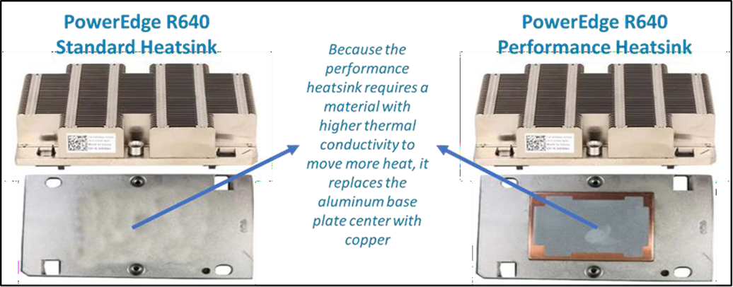
Figure 1. Heat sink base plate uses copper to support higher power
Convection cooling technologies were introduced to server architecture when conduction cooling methods could no longer solely support growing power loads. Convection transfers heat outside of the server through a medium, such as air or liquid. Convection is more efficient than conduction. When the two are used together, they form an effective system - conduction stores heat in a remote location and then convection pushes that heat out of the server.
Technologies such as fans and heat pipes are commonly used in this process. The evolution of fan technology has been extraordinary. Through significant research and development, fan manufacturers have optimized the fan depth, blade radius, blade design, and material, to present dozens of offerings for unique use cases. Factors such as the required airflow (CFM) and power/acoustic/space/cost constraints then point designers to the most appropriate fan. Variable speed fans were also introduced to control fan speeds based on internal temperatures, thereby reducing power usage. Heat pipes have also undergone various design changes to optimize efficiency. The most popular type has a copper enclosure, sintered copper wick, and cooling fluid. Today they are often embedded in the CPU heatsink base, making direct contact with the CPU, and routing that collected heat to the top of the fins in a remote heatsink.
Layout refers to the placement and positioning of the components within the server. As component power requirements increased at a faster rate than conduction and convection technologies were advancing, mechanical architects were pressed to innovate new system layout designs that would maximize the efficiency of existing cooling technologies. Some key tenets about layout design optimization have evolved over time:
- Removing obstructions in the airflow pathway
- Forming airflow channels to target heat generating components
- Balancing airflow within the server by arranging the system layout in a symmetrical fashion
Automation is a newer software approach used to enable a finer control over the server infrastructure. An autonomous infrastructure ensures that both the server components and cooling technologies are working only as hard as needed, based on workload requirements. This lowers power usage, which reduces heat output, and ultimately optimizes the intensity of surrounding cooling technologies. As previously mentioned, variable fan speeds were a cornerstone for this movement, and have been followed by some interesting innovations. Adaptive closed loop controllers have evolved to control fan speed based on thermal sensor inputs and power management inputs. Power capping capabilities ensure thermal compliance with minimum performance impact in challenging thermal conditions. For Dell PowerEdge servers, iDRAC enables users to remotely monitor and tackle thermal challenges with built-in features such as system airflow consumption, custom delta-T, custom PCIe inlet temperature, exhaust temperature control, and adjustment of PCIe airflow settings. The following figure illustrates the flow of these iDRAC automations:
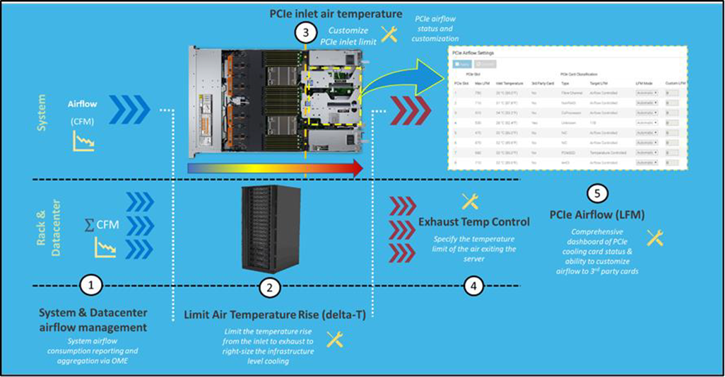
Figure 2. Thermal automations enabled by Dell proprietary iDRAC systems management
Legacy data center cooling techniques
Heat transfer through convection is rendered useless if the intake air being moved by fans is not colder than the heated air within the server. For this reason, cooling the data center room is as important as cooling the server: the two methods depend on one another. Three main approaches to data center cooling have evolved over time – raised floors, hot and cold aisles, and containment, in chronological order. Raised floors were the first approach to cooling the data center. At the very beginning, chillers, and computer room air conditioning (CRAC) units were used to push large volumes of cooled air into the datacenter, and that was enough.
However, the air distribution was wildly unorganized and chaotic, having no dedicated paths for hot or cold airflow, causing many inefficiencies such as recirculation and air stratification. Because adjustments were required to accommodate increasing power demands, the data center floor plan was redesigned to have raised floor systems with perforated tiles replacing solid tiles. This provided a secure path for the cold air created by CRAC units to stay chilled as it traveled beneath the floor until being pulled up the rack by server fans.
Hot and cold aisle rack arrangements were then implemented to assist the raised floor system when the demands of increasing heat density and efficiency could not be met. This configuration has cool air intakes and warm air exhausts facing each other at each end of a server row. Convection currents are then generated, which helped to improve airflow. However, this configuration was still unable to meet the demands of growing data center requirements, as airflow above the raised floors remained chaotic. Something else was needed to maximize efficiency.
Containment cooling ideas propagated to resolve the turbulent nature of cool and hot air mixing above raised floors. By using a physical barrier to separate cool server intake air from heated server exhaust air, operators were finally able to maintain tighter control over the airstreams. Several variants of containment exist, such as cold aisle containment and hot aisle containment, but the premise remains the same – to block cold air from mixing with hot air. Containment cooling successfully increased data center cooling efficiency, lowered energy consumption, and even created more flexibility within the data center layout (as opposed to hot and cold aisle rack arrangements, which require the racks to be aligned in a certain position). Containment cooling is commonly used today in conjunction with raised floor systems. The following figure illustrates what a hot aisle containment configuration might look like:

Figure 3. Hot aisle containment enclosure diagram, sourced from Uptime Institute
What’s Next?
Clearly the historical evolution of these thermal techniques has aided the progression of server and data center technology, enabling opportunities for innovation and business growth. Our next-generation of PowerEdge servers will see technological capabilities jump at an unprecedented magnitude, and Dell will be prepared to get our customers there with the help of our new and existing liquid cooling technologies. Part 2 of this three part series will discuss why power requirements will be rising so aggressively in our next generation PowerEdge servers, what benefits this will yield, and which liquid cooling solutions Dell will provide to keep our customers’ infrastructure cool and safe.

Multi Vector Cooling 2.0 for Next-Generation PowerEdge Servers
Mon, 16 Jan 2023 13:44:20 -0000
|Read Time: 0 minutes
Summary
Next-generation PowerEdge servers (15G) support the latest compute, storage and networking technologies with the help of innovation in hardware and thermal controls design that builds on the foundations of the previous-generation (14G) MVC 1.0 solution. This DfD outlines the new MVC 2.0 innovations on both the hardware thermal design and system thermal controls front that enables maximum system performance, with an eye on thermal efficiency and key customizations desired by customers to tune the system to their deployment needs and challenges.
Introduction
Next-generation PowerEdge servers (15G) support higher-performance CPUs, DIMMs and networking components that will greatly increase the servers’ capabilities. However, as capabilities increase, so does the need for continued innovation to keep the system cool and running efficiently.
Multi Vector Cooling (MVC) is not any specific feature – rather it is a term that captures all of the thermal innovations implemented onto PowerEdge platforms. MVC 2.0 for next-generation PowerEdge servers builds upon existing innovations with additional support in hardware design, improved system layout, and cutting-edge thermal controls. These improvements address the needs of an ever-changing compute landscape, demanding a ‘green performance’, low carbon footprint, as well adding customization levers to optimize not only at the server level, but also at the data center level, generally with airflow handling and power delivery.
Hard Working Hardware
While most of the innovations for MVC 2.0 center around optimizing thermal controls and management, the advancement of physical cooling hardware and its architecture layout is clearly essential:
- Fans - In addition to the cost-effective standard fans, multiple tiers of high performing, Dell-designed fans are supported to increase system cooling. The high performance silver and gold fans can be configured into next-generation PowerEdge servers for supporting increased compute density. Figure 1 below depicts the airflow increase (in CFM) for these high performance fans when compared to baseline fans.
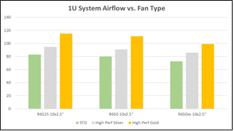
Figure 1 – Comparison of airflow output in CFM
- Heatsinks - The improved CPU heatsink design not only improves CPU cooling capability, but also helps in streamlining airflow and air temperature distribution across the chassis. Innovative heatsink ‘arms’ with high performance heat pipes and optimized fin spacing achieve this goal.
- Layout - The T-shape system motherboard layout, along with PSUs that are now located at each corner of the chassis, allows improved airflow balancing and system cooling, and consequently, improved system cooling efficiency. This layout also improves PSU cooling due to reduced risk from high pre-heat coming from CPU heatsinks, and the streamlined airflow helps with PCIe cooling as well enabling support for PCIe Gen4 adapters. Lastly, this layout creates a better cable routing experience on the PDU side of the racks where power cables are generally separated by grid assignments for redundancy.
AI Based Thermal Controls
To best supplement the improved cooling hardware, the PowerEdge engineering team focused on developing a more autonomous environment. Key features from prior-generations were expanded upon to deliver thermal autonomous solutions capable of cooling next-generation PowerEdge servers. Our AI based proprietary and patented fuzzy logic driven adaptive closed loop controller has been expanded to not just do fan speed control based on thermal sensor input but is now utilized for power management. This allows for the optimization of system performance, especially in transient workloads and systems operating in challenging thermal environments by automating power management that is required beyond fan speed control for thermal management.
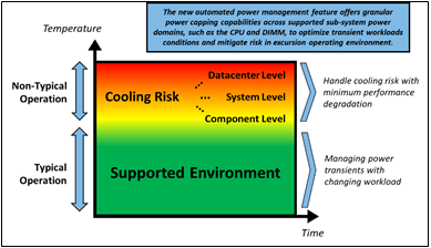
Figure 2 – Each operating environment has unique challenges
This automation with granular power capping capability across various supported sub -system power domains (more specifically CPU and DIMM) ensures thermal compliance with minimum performance impact in challenging thermal conditions. See Figure 2 for illustrates area where new controls solution optimize system performance and uptime.
iDRAC Datacenter Thermal Management Features and OME
With introduction of iDRAC Datacenter license and OME’s power manager one-to-many capabilities, customers can monitor and tackle challenges associated to server customizations as well as deployment in their datacenter (power and airflow centric). Below list highlights some of the key features:
- System Airflow Consumption - Users can view real-time system airflow consumption (in CFM), allowing airflow balancing at the rack and datacenter level with newly added integration in the OME Power Manager
- Custom Delta-T - Users can limit the air temperature rise from the inlet to exhaust to right-size their infrastructure level cooling
- Custom PCIe inlet temperature - Users can choose the right input inlet temperature to match 3rd party device requirements
- Exhaust Temperature Control - Users can specify the temperature limit of the air exiting the server to match their datacenter hot aisle needs or limitations (personnel presence, networking/power hardware)
- PCIe airflow settings - Users are provided a comprehensive PCIe devices cooling view of the server that informs and allows cooling customization of 3rd party cards
Figure 3 illustrates how the features previously mentioned work together at a system level:
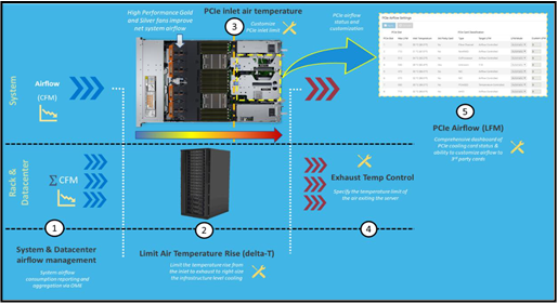
Figure 3 – iDRAC thermal management features and customizations
Channel Card Support
Dell Technologies also offers flexibility for customers wanting to implement non-Dell channel cards. Comprehensive support for PCIe communication standards like PLDM, NC-SI and custom implementations by vendors for GPUs and accelerators, such as Nvidia, AMD, Intel for temperature monitoring and closed loop system fan control. Channel cards that follow these standards will therefore have optimal thermal and power management behavior in PE Servers. Future updates would also include suppo rt of new open loop cooling levels defined in latest release of PCIe-SIG standards document.
Conclusion
The Dell Technologies MVC 2.0 solution enables next-generation (15G) PowerEdge servers to support dense configs and workloads with higher-performance cooling hardware, increased automation, simplified but advanced management and channel card flexibility. By expanding upon the existing MVC 1.0 design strategy, the MVC 2.0 solution resolves new thermal challenges so that PowerEdge customers can fully utilize their datacenters while managing the deployment constraints like airflow and power delivery in an optimal fashion.