


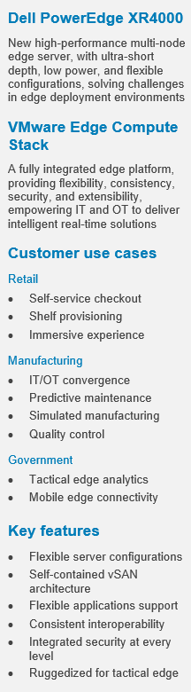
Dell PowerEdge XR4000 with VMware Edge Compute Stack for Edge Computing
Download PDFThu, 31 Aug 2023 17:42:58 -0000
|Read Time: 0 minutes
Overview
Enterprises want to build and operate applications that have low latency requirements to process and analyze real-time data, and they want to provide intelligence for smarter decision-making at the edge. However, they face many challenges: aging infrastructure, limited edge-computing resources, environmental factors, and lack of IT staff to deploy and support applications across many edge sites.
This document provides an overview of a combined edge platform built on Dell PowerEdge XR servers and VMware Edge Compute Stack to solve these challenges. It describes key use cases in retail, manufacturing, and other industries.
The PowerEdge XR server series is built to capture and process more data at the edge, with enterprise-grade compute abilities providing high performance with low latency for the edge. The XR servers can withstand unpredictable and challenging deployment environments. XR4000 is the new high-performance multi-node XR server, purpose-built for ultra-short depth and low power, and with flexible configurations. These configurations are also available on our Dell vSAN Ready Nodes.
- 1S Intel® Ice Lake Xeon-D® with integrated security and cyber-resilient architecture
- 355-mm-deep chassis with wall-mount option
- Rugged operating range from –5°C to 55°C (32°F to 131°F)
- Flexible 1U and 2U compute sled; self-contained 2-node for VMware vSAN cluster
Edge Compute Stack (ECS) is a fully integrated edge platform for customers with many edge sites. ECS empowers IT and OT to deliver intelligent real-time solutions, offering flexibility, consistency, security, and extensibility:
- Flexibility to run virtual and container applications, standard and real-time operating systems
- Consistent interoperability across edges, data centers, and clouds
- Security to protect applications, users, devices, and data against threats
- Open platform that offers component choices and extensibility
This document includes a combined XR4000 and ECS reference architecture validated and supported by Dell Technologies and VMware. It also provides sample configurations for customers and partners to use as a starting point to design and implement the combined edge platform.
Customer use cases
Key use cases for the solution are in the retail, manufacturing, and government sectors.
Retail
Retailers adapted to the pandemic with increased use of self-service checkout and new delivery mechanisms. They are deploying edge applications to improve customer experience and profitability:
- Self-checkout—Camera and computer vision solutions help prevent loss from missed scans and switched products or price stickers by instantaneously matching products with prices.
- Optimal shelf provisioning—Inventory tracking and data analysis solutions can optimize shelf-provisioning to increase sales.
- Immersive experience—Interactive mirrors in apparel stores give customers an immersive experience when they are trying out an item by providing additional colors or variations.
- POS—Virtualize and extend the point-of-sale life cycle and realize impactful ROI through faster innovation, a transformative customer experience, and proactive management of retail infrastructure.
The XR4000 and ECS platform provides high flexibility and performance to deploy and run these retail solutions while optimizing expensive retail space and meeting store environmental requirements.
Manufacturing
The Industry 4.0 movement is digitizing manufacturing for greater efficiency and flexibility. Manufacturers are deploying edge applications for the following use cases:
- IT/OT convergence—Virtualization of industrialized PCs and programmable logic controllers (PLCs) enabled skilled operators to work from anywhere with low latency while allowing OT and IT applications to run on the same hardware for greater efficiency.
- Predictive maintenance—Solutions that use smart sensor data can reduce machine downtime by 50 percent.
- Simulated manufacturing—Digital twin software creates a simulation running in parallel to physical machines to optimize operational efficiency.
- Quality control—Computer vision can spot defects to increase quality and yield.
The XR4000 and ECS platform provides a foundation for these solutions for machine aggregation and virtualization, OT/IT translation, industrial automation, and AI inferencing.
Government
Defense, law enforcement, and emergency response organizations have specific requirements for tactical and mobile edge deployments:
- Tactical edge—Military and civil defense organizations are implementing real-time analytics solutions using ruggedized form factors at the tactical edge.
- Mobile edge—Law enforcement and emergency response organizations are adopting vehicle-based mobile edge solutions.
XR4000 is highly portable and hardened for dusty, hot/cold operations. It is tested with NEBS Level 3 and MIL certifications. With ruggedized ATA-compliant compact and mobile systems from Dell OEM partners, the XR4000 and ECS platform is ideal for tactical and mobile edge workloads.
Features
Figure 1 illustrates the combined XR4000 and ECS reference architecture. It consolidates VMs and the Kubernetes management cluster in the central data center. It also includes self-contained 2-node vSAN and TKG Multi-Cloud (TKGm) clusters at every edge site. A purpose-built vSAN witness node XR4000w (Nano Processing Unit, shown in Figure 2) is integrated within several XR4000 chassis options, enabling a highly efficient and reliable edge stack. An optional SD-WAN virtual edge can provide optimal connectivity and additional security. The centralized VMware vCenter and TKG management cluster simplify vSAN and TKGm deployment at the edge sites.
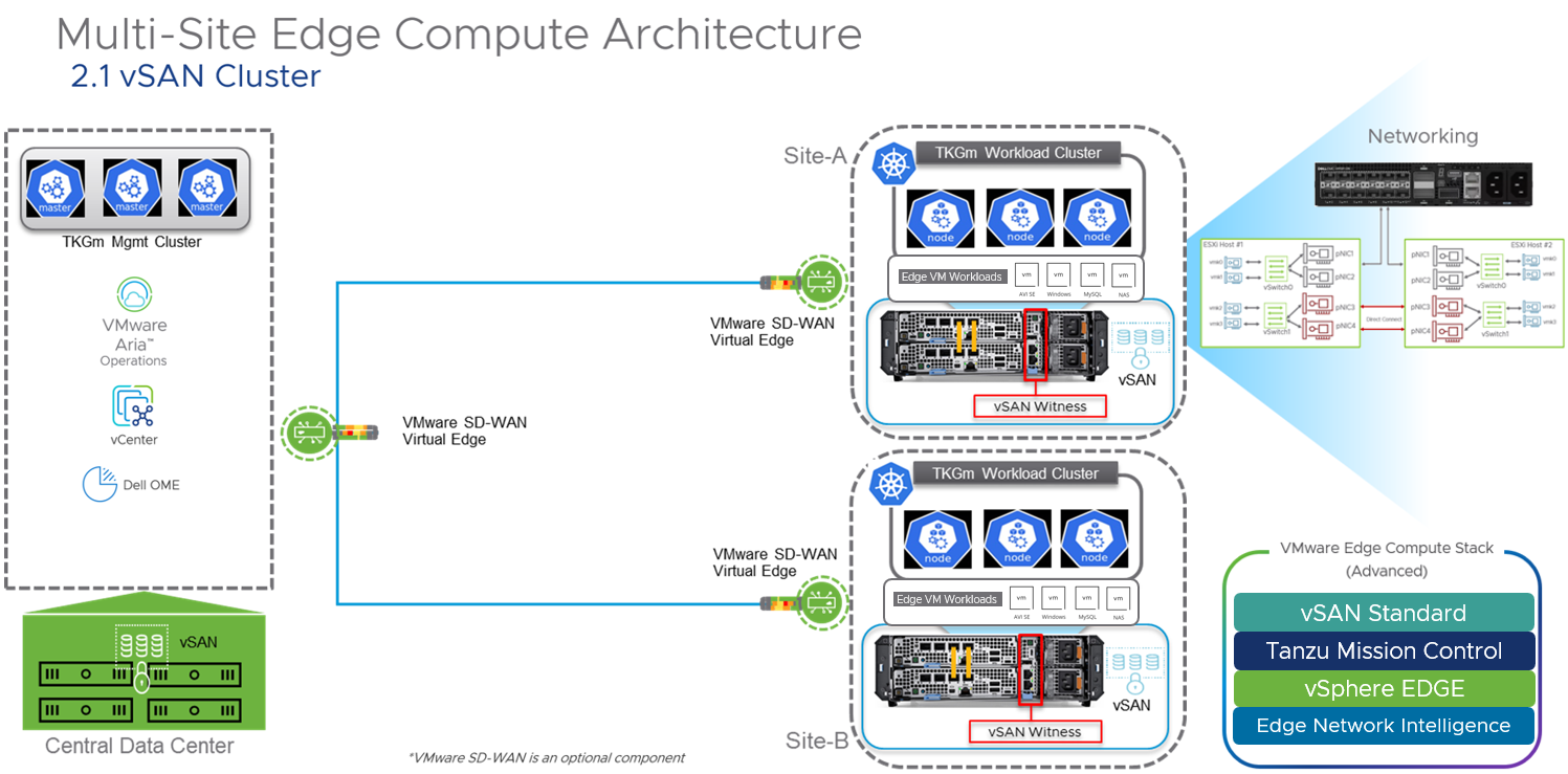
Figure 1. XR4000 and ECS reference architecture
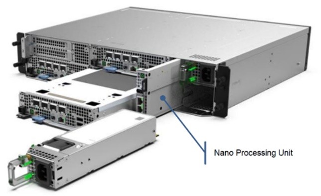
Figure 2. Nano Processing Unit
PowerEdge XR4000 and Edge Compute Stack configurations
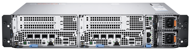
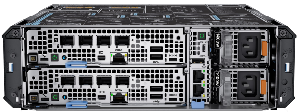
Dell PowerEdge XR4000 is a rugged multi-node edge server available in two unique and flexible form factors. The “rackable” chassis supports up to four 1U sleds; the “stackable” chassis supports up to two 2U sleds. The 1U sled is provided for dense compute requirements. The 2U chassis shares the same “1st U” and common motherboard with the 1U sled but includes an additional riser to provide two more PCIe Gen4 FHFL I/O slots. Customers who need additional storage or PCIe expansion can choose a 2U sled option. All XR4000 chassis support both front-to-back and back-to-front airflow.
Sample configurations
The following table provides details for two sample configurations—one rackable and the other stackable.
Table 1. Sample configurations
| Rackable configuration 2 x 2U | Stackable configuration 2 x 1U |
|
|
|
Edge Compute Stack (ECS) | VMware ECS Advanced (vSphere Edge, vSAN Standard for Edge, Tanzu Mission Control Advanced), 1/3/5-year term license, up to 128 cores per edge instance | |
Chassis | Dell PowerEdge XR4000r 2U, 14 inches deep,19 inches wide | Dell PowerEdge XR4000z 2U, 14 inches deep, 10.5 inches wide |
Mounting options | Mounting ears to support a standard 19-inch-wide rack | Deployed in desktop, VESA plates, DIN rails, or stacked environments |
Power supply | Front port access, dual, hot-plug (1+1), 1400 W, RAF | |
Operating range | –5°C to 55°C (32°F to 131°F) | |
Witness node | 1 x Dell PowerEdge XR4000w, VMware Certified | |
Server
| 2 x Dell PowerEdge XR4520c sleds, VMware Certified | 2 x Dell PowerEdge XR4510c sleds, VMware Certified |
Total capacity of 2 x 2U sleds | Total capacity of 2 x 1U sleds | |
Security | Trusted Platform Module 2.0 V3 | |
CPU cores* | 32 cores (2 x 1S Intel Ice Lake Xeon-D 16 cores CPU) | |
Memory* | 256 GB (8 x 32 GB RDIMM) | 128 GB (8 x 16 GB RDIMM) |
Boot drive | 2 x BOSS-N1 controller card + with 2 M.2 960 GB - RAID 1 | 2 x BOSS-N1 controller card + with 2 M.2 480 GB - RAID 1 |
Storage* | 15.2 TB (8 x 1.9 TB, SSDR, 2E, M.2) | |
Network | 4 x 10 GbE Base-T or SFP for 4/8 core CPU; | |
GPU (optional) | 2 x NVIDIA Ampere A2, PCIe, 60 W, 16 GB Passive, Full Height GPU, VMware Certified | Not Applicable |
System management | iDRAC9, Dell OpenManage Enterprise Advanced Plus, integration for VMware vCenter | |
*In a High Availability (HA) 2-node vSAN cluster, for failover to work properly, total consumable CPU, Memory, and Storage for application workloads should not exceed the available resources of a single node.
Engage Dell and VMware
The edge platform built on Dell PowerEdge XR4000 server and VMware Edge Compute Stack aims to help retail, manufacturing, and government customer organizations build and operate applications that provide intelligence for smarter decision-making and deliver immersive digital experiences at the edge. The combined reference architecture and configuration examples described in this document are designed to help our joint customers in designing and implementing a consistent, flexible, secure, and extensible edge solution.
To learn more about the flexible configurations of the Dell XR4000 chassis and compute sleds, see PowerEdge XR Rugged Servers.
For more information about VMware Edge Compute Stack, see VMware Edge Compute Stack and contact the VMware team at edgecomputestack@vmware.com.
References
- Dell PowerEdge XR4000 Specification Sheet
- Dell PowerEdge XR4000r Chassis
- Dell PowerEdge XR4000: Multi-Node Design
- VMware SASE and Edge
- How is VMware Edge Compute Stack Accelerating Digital Transformation Across Industries?
Related Documents

Deploy HCI with Ease on VMware vSAN Ready Nodes™

Tue, 17 Jan 2023 06:59:21 -0000
|Read Time: 0 minutes
Summary
Hyperconverged infrastructure is changing the way that IT organizations deliver resources to their users. In this short joint reference document with Dell Technologies and Intel we discuss the critical hardware components needed to successfully deploy vSAN. The information in this publication is provided as is. Dell Inc. makes no representations or warranties of any kind with respect to the information in this publication, and specifically disclaims implied warranties of merchantability or fitness for a particular purpose.
The surge in remote work and virtual desktop infrastructure (VDI) is increasing resource demands in the data center. As a result, many enterprises are turning to hyperconverged infrastructure (HCI). But HCI implementation can be complex and time-consuming. VMware vSAN ReadyNode™ provides a turnkey solution for accelerating HCI.
vSAN ReadyNode is a validated configuration on Dell EMC™ PowerEdge™ servers. These servers are tested and certified for VMware vSAN™ deployment, jointly recommended by Dell and VMware. vSAN ReadyNode on Dell EMC PowerEdge servers can help reduce HCI complexity, decrease total cost of ownership (TCO), scale with business needs and accommodate hybrid-cloud solutions such as VMware Cloud Foundation™. Benefits include the following:
- License efficiency—Get the most from each software license. vSAN ReadyNode on Dell EMC PowerEdge servers is designed to provide the best performance for each VMware® license per 32-core socket.
- High throughput—Elastic, scalable storage is one of many vSAN benefits. vSAN ReadyNode on Dell EMC PowerEdge servers, built on high-performing Intel architecture, prioritizes storage throughput with fast write caching and capacity storage tiers.
- Low latency—As a vSAN deployment grows, and data needs to be accessed across the cluster, data-access response times become increasingly important. This architecture, featuring Intel Ethernet Network Adapters, takes advantage of VMware’s recent addition of remote direct memory access (RDMA) to improve data response and user experience.
Key Considerations
- Available in two configurations—Both the “Base” and “Plus” configurations use similar all-flash NVM Express® (NVMe®) storage configurations. However, the Plus configuration is equipped with a higher-frequency CPU and Intel® Optane™ persistent memory (PMem). Both configurations are based on Intel® Select Solutions for VMware vSAN 7 HCI with 3rd Generation Intel® Xeon® Scalable processors.
- Networking—Both configurations are equipped with RDMA-capable Intel® Ethernet 800 Series network adapters that accelerate vSAN 7 performance (7.0 U2 or later). The Intel Ethernet Network Adapter E810- XXV network interface controller (NIC) can be used for network- and storage-intensive workloads requiring more than 25 gigabits per second (Gbps) of bandwidth.
- Rack-space requirements—The rack-space-optimized Dell EMC PowerEdge R650 server–based system can be used if large storage capacity is not needed (up to two storage groups are supported, each with a single cache drive and up to four capacity drives, with a maximum of 10 NVMe drives per system). For more drives or future- capacity scaling, the Dell EMC PowerEdge R750 server–based system is recommended.
Available Configurations
| Base configuration | Plus configuration | ||
Platform | Dell EMC™ PowerEdge™ R650, supporting 10 NVMe® drives (direct connection with no Dell™ PowerEdge RAID Controller [PERC]), 1RU | Dell EMC PowerEdge R750, supporting 24 NVMe drives (direct connection with no Dell PERC), 2RU | Dell EMC PowerEdge R650 supporting 10 NVMe drives (direct connection with no Dell PERC), 1RU | Dell EMC PowerEdge R750 supporting 24 NVMe drives (direct connection with no Dell PERC), 2RU |
CPU | 2 x Intel® Xeon® Gold 6338 processor (32 cores at 2.0 GHz) | 2 x Intel® Xeon® Platinum 8358 processor (32 cores at 2.6 GHz) or 2 x Intel® Xeon® Platinum 8362 processor (32 cores at 2.8 GHz) | ||
DRAM | 512 GB (16 x 32 GB DDR4-3200) | 256 GB (16 x 16 GB DDR4-3200) | ||
Persistent Memory | Optional | 1 TB (8 x 128 GB Intel® Optane™ PMem 200 series) | ||
Boot device | Dell EMC™ Boot Optimized Server Storage (BOSS)-S2 with 2 x 480 GB Intel® SSD S4510 M.2 Serial ATA (SATA) (RAID1) | |||
Storage adapter | Not required for an all-NVMe configuration | |||
Cache tier drives | 2 x 400 GB Intel Optane SSD P5800X (PCIe Gen4) or 2 x 375 GB Intel Optane SSD DC P4800X (PCIe Gen3)i | |||
Capacity tier drives | 6 x (up to 8 x) 3.84 TB Intel SSD DC P5500 (PCIe Gen4, read- intensive) | 6 x (up to 12 x) 3.84 TB Intel SSD DC P5500 (PCIe Gen4, read- intensive) | 6 x (up to 8 x) 3.84 TB Intel SSD DC P5500 (PCIe Gen4, read- intensive) | 6 x (up to 12 x) 3.84 TB Intel SSD DC P5500 (PCIe Gen4, read-intensive) |
NIC | Intel® Ethernet Network Adapter E810-XXV for OCP3 (dual-port 25 Gb)ii | |||
Get Started
View the vSAN Hardware Quick Reference Guide and VMware Compatibility Guide.
Learn More
- Contact your Dell or Intel account team. 1-877-289+-3355
- Read the Principled Technologies report: Reap better SQL Server OLTP performance with next-generation Dell EMC PowerEdge MX servers.
- Read the science behind the Principled Technologies report.
- View the Principled Technologies infographic.
i The Intel® Optane™ SSD P5800X is recommended, but the previous-generation Intel Optane SSD DC P4800X can be used instead if the Intel Optane SSD P5800X is not yet available.
ii When used with VMware vSAN™, the Intel® Ethernet Network Adapter E810-XXV for OCP3 requires appropriate RDMA firmware.

VMware Cloud Foundation 5.1 on next gen Dell PowerEdge servers
Thu, 16 May 2024 15:42:24 -0000
|Read Time: 0 minutes
A Principled Technologies deployment guide
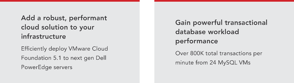
The release of VMware Cloud Foundation™ 5.1 offers new scalability, security, and enhancements that can help organizations meet essential infrastructure-as-a-service (IaaS) requirements. When backed by next gen Dell™ PowerEdge™ servers (with their own advantages in performance, security, management, and more), the VMware and Dell solution could deliver a robust, scalable, and efficient on-premises cloud infrastructure that provides the underlying infrastructure for your business to achieve your strategic business goals.
This comprehensive guide explains the deployment process for VMware Cloud Foundation 5.1 on a cluster of Dell PowerEdge servers, steps that we verified by doing the work ourselves. As your organization continues to evolve in the dynamic landscape of modern IT, this guide can empower your system administrators, architects, and IT professionals with the knowledge and expertise to implement the VMware and Dell cloud solution efficiently and effectively.
In addition to verifying the straightforward deployment process of VMware Cloud Foundation 5.1 on next gen Dell PowerEdge servers, we ran an online transaction processing (OLTP) workload on 24 VMs configured with MySQL database software. The consistent new orders per minute (NOPM) metrics that we captured demonstrate the potential transactional database performance value that the VMware and Dell cloud solution can deliver.
About 16th Generation Dell PowerEdge servers
With enhanced processing power, advanced security features, and transformative management capabilities, the 16th Generation servers can offer strong standards of server performance for your data center. According to Dell, “Whether your applications and data reside in the cloud, data centers, or edge environments, Dell’s PowerEdge portfolio empowers you to harness the full ease and agility of the cloud.”[i] Learn more about the portfolio of 16th Generation Dell PowerEdge rack, tower, purpose-built, and modular infrastructure servers.
VMware Cloud Foundation 5.1 overview
VMware Cloud Foundation (VCF) 5.1 allows your organization to build and operate a robust private or hybrid cloud infrastructure, seamlessly integrating essential resources and services into a unified platform. Boasting features such as automated lifecycle management and intrinsic security, Cloud Foundation 5.1 can simplify the deployment and management of cloud environments while ensuring efficiency.
This latest release includes security updates, fixes for UI and Lifecycle Management issues, enhancements to prechecks at the bundle level for VMware vCenter®, and several key enhancements that address requirements for cloud scale infrastructure.[ii],[iii] It provides a complete set of software-defined services for compute, storage, network, and security, along with cloud management capabilities.[iv],[v]
Learn more about VCF 5.1.
VMware Cloud Foundation components
VCF 5.1 comprises the following:
• VMware vSphere®
• VMware NSX®
• VMware vSphere with Tanzu™
• VMware ESXi™ 8.0 U1
• VMware vCenter Server® 8.0 U1
• VMware vSAN™ 8.0 U1
• VMware Aria Suite™
• VMware Cloud Builder
• VMware Software-Defined Data Center (SDDC) Manager 5.0.[vi]
VCF automates deployment and configuration of the private or hybrid cloud software stack for your virtual infrastructure. The initial VCF deployment creates a management domain that you can then use to add workload domains. Workload domains consist of clusters of at least three ESXi hosts and can manage and segregate resources and workloads in your private cloud.
For deploying and overseeing the logical infrastructure within the private cloud, VCF incorporates Cloud Builder and SDDC Manager virtual appliances to enhance VMware virtualization and management elements. These components were essential in our deployment to the next gen Dell PowerEdge server cluster.
VMware Cloud Builder automates the deployment of the management domain, the first cluster in a VCF deployment that manages the health of the VCF stack and the deployment of workload domains (server clusters that you use to run workload VMs).
SDDC Manager automates the virtualization software life cycle, encompassing configuration, provisioning, upgrades, and patching, including host firmware, while simplifying day-to-day management and operations. Through the SDDC Manager interface, which Figure 1 shows, the virtual infrastructure administrator or cloud administrator can provision new private cloud resources, monitor changes to the logical infrastructure, and oversee life cycle and other operational activities.

Figure 1: The VMware SDDC Manager interface. Source: Principled Technologies.
SDDC Manager uses vSphere Lifecycle to bundle, stage, and deploy software, OS, and firmware updates on a per-workload domain basis.
Additionally, VMware lists other features that we did not use in our deployment but that could be helpful in your next gen Dell PowerEdge cluster environment:[vii]
- vSphere with Tanzu/Workload Management integration to run Kubernetes workloads natively in vSphere
- vSAN stretched cluster configuration to provision two availability zones in a single workload domain, including a management domain, which could provide native high availability and physical resiliency and could minimize management service and workload downtime
- NSX Federation to manage network configuration across multiple VCF instances and management domains
- VMware Cloud Foundation+ to connect to VMware Cloud® using a subscription model rather than key-based component licensing and to manage your VCF instance via the VMware Cloud Console
Setting up the next gen Dell PowerEdge servers
The Dell PowerEdge servers that comprised our cluster included the following:
- Four Dell PowerEdge R750xs servers for management domain
- Three Dell PowerEdge R760 servers for virtual infrastructure workload domain
We deployed the VCF management domain on the four Dell PowerEdge R750xs servers. Each PowerEdge R750xs server had two BOSS drives for VMware ESXi 8.0.2 and eight SAS SSDs for VMware vSAN storage. The VCF management domain uses its own vCenter, NSX networking, and vSAN storage. To deploy and configure those resources and SDDC Manager automatically during the Cloud Builder deployment, VCF used our configuration details from the Deployment Parameter Workbook. This is an Excel workbook where you enter credentials, IPs, VLANs, and other configuration details for the VCF deployment and then upload it to Cloud Builder, which tests the input and allows you to continue deploying VCF once everything passes validation.
After deploying the VCF management domain, we deployed a virtual infrastructure (VI) workload domain on the three Dell PowerEdge R760 servers. Each Dell PowerEdge R760 server had two BOSS drives for ESXi 8.0.2, and four NVMe® drives and 20 SAS SSDs for vSAN storage. VI workload domains are additional vSphere clusters of at least three hosts with their own storage (in our case vSAN) and their own vCenter Server instance. VI workload domains provide physical and logical units for segregating and managing customer workloads.[viii]
All the Dell PowerEdge servers in our testbed had two 25Gb Ethernet connections to a Dell S5248F switch. We also used a Dell PowerEdge R6625 server as an infrastructure server where we deployed the AD/DNS server, the Certificate Authority server, a jumpbox VM, and routers to manage the VLANs on the Dell S5248F switch.
Overview of our VCF 5.1 deployment on a Dell PowerEdge server cluster
Figure 2 shows an example of how you can deploy all management components in VMware Cloud Foundation, which was the general process we followed.

Figure 2. Example flow chart of a VMware Cloud Foundation 5.1 deployment. Source: Principled Technologies based on VMware Deployment Overview of VMware Cloud Foundation.
You can install VCF 5.1 either “as a new release or perform a sequential or skip-level upgrade to VMware Cloud Foundation 5.1.”[ix] The new installation process, which we broadly followed, has three phases:[x]
- Preparing the environment: “The Planning and Preparation Workbook provides detailed information about the software, tools, and external services that are required to implement a Software-Defined Data Center (SDDC) with VMware Cloud Foundation, using a standard architecture model.”[xi] Note: Unlike the Deployment Parameter Workbook, an Excel file that you complete and upload to Cloud Builder, the Planning and Preparation Workbook is a long list of values, IPs, VLANs, domain names, usernames, passwords, etc. Your infrastructure team completes it with all the environment details and you use that as reference throughout the deployment process, but do not upload it at any point.
- Imaging all servers with ESXi: “Image all servers with the ESXi version mentioned in the Cloud Foundation Bill of Materials (BOM) section. See the VMware Cloud Foundation Deployment Guide for information on installing ESXi.”[xii] We installed the latest Dell-customized ESXi 8 version to each host under test at the start of testing and configured the OS as the Planning and Preparation Workbook specified.
- Installing Cloud Foundation 5.1: VMware Cloud Builder handles the bulk of the VCF deployment. Using the Planning and Preparation Workbook, in conjunction with the automation of VCF, made our deployment a smooth and almost entirely automated process. (Once you have uploaded the workbook and it passes validation with no errors, you click a button to kick off the automated deployment of the management domain.)
Key takeaway
Less-experienced infrastructure administrators might find some difficulty in setting up VMware Cloud Foundation due to the complex initial environment requirements, such as DNS, networking/IP pools, and preparing hosts and disks. In our experience, however, the validation process of the Parameter Workbook helped with troubleshooting and ensuring accuracy before our deployment. Once the software successfully validated the workbook, Cloud Builder fully automated the VCF deployment, including vSAN, NSX, vCenter, and SDDC Manager. This makes deployment much easier and faster for admins at any level rather than manually completing the same processes.
Deploying VMware Cloud Foundation 5.1 on Dell PowerEdge servers
Getting started
Note that we deployed our solution by following the steps in this document but skipped some optional steps, such as including Workspace ONE.
Prior to deploying VCF via the VMware Cloud Builder, we set up infrastructure components in our environment, including the following:
- A Windows Server 2022 VM that we configured as an Active Directory domain controller for our VCF domain (in our case, we used vcfdomain.local)
- This VM also included a DNS server with forward and reverse lookups for core infrastructure components as defined by the Planning and Preparation workbook, including fully qualified domain names (FQDNs) for SDDC Manager, vCenter, and other key components of the VCF deployment
- This VM also hosted an internal NTP server for VCF hosts
- DNS with forward and reverse lookups for all relevant DNS entries
- Another Windows Server 2022 VM that we configured as a child domain controller joined to the primary VCF domain that served as the Active Directory Certificate Services role
- SDDC Manager used this domain as an internal Certificate Authority to allow trusted communication between the various VCF components
- Other necessary infrastructure components, such as pfsense VMs to handle inter-VLAN routing, DHCP, and provide NAT to the internal network where we deployed VCF
- Configuring our Dell S5248F switch as required by the Planning Workbook
We also configured static IPs for the management domain hosts and vSAN ready disks for the management cluster.
Using the Planning and Preparation Workbook
We filled out the VCF Planning and Preparation Workbook with our environment’s details. This is a Microsoft Excel workbook that serves as a configuration guide for the required VCF components and for select components after the automated deployment. Download the Planning and Preparation Workbook.
Our environment details included our supporting virtual infrastructure and IP addresses, hostnames, credentials, and other relevant details. Some of these VMware Cloud Builder automatically configured during the deployment and others we manually configured after the deployment. As we mentioned earlier, this Planning and Preparation Workbook is different from the VCF Deployment Parameter Workbook, which we used to define the environment details for the automated VCF deployment via the Cloud Builder appliance.
Imaging the servers
After we fully populated the workbook, we followed the steps from this document to prepare the individual hosts for the management domain:
- We installed ESXi on each of the hosts. We used ESXi 8.0.2 build 22380479 (Dell Customized), the most recent Dell-customized ESXi 8 version at the time.
- We configured networking on each of the hosts. We used the ESXi direct console UI to set the network adapter, hostname, static IP address, subnet mask, gateway, and DNS as specified in the planning workbook. We also enabled SSH in troubleshooting options.
- We logged into the ESXi host client for each host and started the NTP server. We also ensured that the SSH service was running.
- After setting the hostnames, we regenerated the self-signed certificates on each host so that the common name of the certificate included the hostname. We connected to each host using SSH, regenerated the self-signed certificate, and restarted the hostd and vpxa services.
Installing VMware Cloud Builder
We then finished by populating the Deployment Parameter Workbook with our environment details, networking information, and credentials. (For more information on deploying Cloud Builder, see the guide.)
After preparing all four ESXi hosts for the management domain, we deployed the VMware Cloud Builder appliance to our infrastructure host using the ESXi host client, the Cloud Builder appliance OVA file, and specified admin and root credentials and networking details for the appliance. After we deployed Cloud Builder, we connected to the Cloud builder VM via SSH and confirmed that it could successfully ping the ESXi hosts. See this VMware document for more information.
We then logged into the VMware Cloud Builder appliance web interface by navigating to its FQDN in a web browser and following the steps listed on the web interface. The steps consisted of filling out the VCF Deployment Parameter Workbook with values from the Planning and Preparation Workbook and then uploading it to the Cloud Builder VCF deployment wizard. Cloud Builder validated the entire configuration as the Deployment Parameter Workbook specified. To learn more about the Deployment Parameter Workbook, visit https://docs.vmware.com/en/VMware-Cloud-Foundation/5.1/vcf-deploy/GUID-08E5E911-7B4B-4E1C-AE9B-68C90124D1B9.html.
After populating the Deployment Parameter Workbook with the relevant networking, existing infrastructure, credentials, and licensing information and testing that everything passed validation in the VMware Cloud Builder, we clicked Deploy SDDC and the Cloud Builder automatically deployed SDDC Manager and the other components of our initial VCF management cluster, including vCenter, NSX Manager, and vSAN.
VMware documentation states that Cloud Builder lists any issues with validation as errors or warnings in the UI. Users must address any configuration or environment errors before continuing. We did not encounter any errors or warnings in our deployment.
After validating and testing the environment parameters, the Cloud Builder appliance used our information to deploy the management domain cluster, consisting of four hosts. The deployment process included deploying a VMware vCenter Server environment, configuring NSX and vSAN, deploying SDDC Manager, and transferring control of the hosts and environment to SDDC Manager.
As we previously noted, VCF is compatible with vSphere with Tanzu workloads and Workload Management for running Kubernetes-based applications and workloads natively on the ESXi hypervisor layer. You could enable Workload Management on the management domain cluster or on specific workload domain clusters. We did not do this in our testing or use vSphere with Tanzu.[xiii]

Figure 3: The VMware Cloud Builder post-deployment success screen. Source: Principled Technologies.
Post-deployment configuration
With our core VCF components and management domain cluster deployed, we needed to complete some steps in SDDC Manager before deploying the first VI workload domain or VMware Aria Suite components.
Based on recommendations in VMware documentation,[xiv] we deployed Aria Operations after the initial management domain deployment and configured the software to provide workload and performance visibility into the VCF management domain and our eventual virtual infrastructure workload domains.
We logged into our newly deployed SDDC Manager instance and configured it to authenticate with VMware Customer Connect to download install and update bundles for Aria Suite Lifecycle Manager and the VI workload domain deployment. We also configured SDDC Manager to use our internal Certificate Authority server to manage CA-signed certificates for the physical infrastructure underlying our VCF deployment. In our management domain, we deployed an NSX Manager and Edge cluster and application virtual networks. We referenced these VMware documents.
Next, we followed the steps in this document to deploy VMware Aria Suite Lifecycle in the management domain. We used SDDC Manager to generate and sign a certificate for Lifecycle Manager by following these steps. We configured Lifecycle Manager to communicate with our management domain vCenter. We did the same for Aria Suite Operations: deployed it to our management domain for visibility into our virtual and physical infrastructure and then configured it in SDDC Manager. See how to configure Lifecycle Manager and more information on deploying Aria Suite Operations. After we installed VMware Aria Operations, the entire VCF management domain deployment was complete (see Figure 3).
Preparing for workload activity
To deploy a VI workload domain cluster, we prepared three new hosts the same way we configured the management domain ESXi hosts. We created a network pool for the workload domain cluster and commissioned them to the SDDC inventory. We then deployed the VI workload domain by following these steps. We deployed an NSX Edge cluster to the workload domain for virtual networking infrastructure and generated certificates in SDDC Manager for the VI workload domain hosts. We considered our workload domain fully configured at this point and ready for our proof-of-concept database workload.
Deploying the OLTP database workload
We used the TPROC-C benchmark from the HammerDB suite to simulate a real-world online transaction processing database workload. We created a VM running MySQL database software on the workload domain cluster with 16 vCPUs, 64 GB of memory, and 2 TB of storage from the VSAN datastore. We installed Ubuntu 22.04 and MySQL 8.0 on the VM. We then scaled out to 24 VMs on each Dell PowerEdge R760 server. We ran the HammerDB 4.9 TPROC-C workload on each VM with 500 warehouses and measured the new orders per minute.
About HammerDB
HammerDB is an open-source benchmarking tool that tests the performance of many leading databases. The benchmark tool includes two built-in workloads derived from industry standards: a transactional (TPROC-C) workload and an analytics (TPROC-H) workload. We chose the TPROC-C (TPC-C-like) workload to demonstrate the online transaction processing performance capabilities of each instance, which benefit from high core counts and fast memory. TPROC-C runs a transaction processing workload that simulates an ecommerce business with five types of transactions: receiving a customer order, recording a payment, delivering an order, checking an order’s status, and checking stock in inventory.[xv] Note that our test results do not represent official TPC results and are not comparable to official TPC-audited results. To learn more about HammerDB, visit https://www.hammerdb.com/.
Get strong cloud OLTP database performance
We ran the TPROC-C workload three times and collected the total NOPM and transactions per minute (TPM) across all 24 MySQL VMs (see Table 1). The median run is in bold.
Table 1: The total new orders per minute and transactions per minute for all 24 MySQL VMs in our testbed. Source: Principled Technologies.
TPROC-C run 1 | TPROC-C run 2 | TPROC-C run 3 | |
Total NOPM | 342,850 | 344,889 | 345,961 |
Total TPM | 796,817 | 801,329 | 803,411 |
Figure 4 shows CPU utilization during the median run (run 2). CPU utilization stayed around 70 percent during the test. We wanted to hit 70 percent utilization to simulate a real-world OLTP workload.

Figure 4: CPU utilization during the median run of our testing. Source: Principled Technologies.
Figure 5 shows the average vSAN storage latencies for the Dell PowerEdge cluster during run 2. Read latency stayed between 1.5 and 2 milliseconds, and write latency stayed 2.5 and 3 milliseconds, showing that storage access stayed relatively low and constant during for the OLTP workload.

Figure 5: Average vSAN storage latencies for the Dell PowerEdge cluster with VCF 5.1. Source: Principled Technologies.
Conclusion
Deploying VMware Cloud Foundation 5.1 on next gen Dell PowerEdge servers brings together critical virtualization capabilities and high-performing hardware infrastructure. Relying on our hands-on experience, this deployment guide offers a comprehensive roadmap that can guide your organization through the seamless integration of advanced VMware cloud solutions with the performance and reliability of Dell PowerEdge servers. In addition to the deployment efficiency, the Cloud Foundation 5.1 and PowerEdge solution delivered strong performance while running a MySQL database workload. By leveraging VMware Cloud Foundation 5.1 and PowerEdge servers, you could help your organization embrace cloud computing with confidence, potentially unlocking a new level of agility, scalability, and efficiency in your data center operations.
This project was commissioned by Dell Technologies.
May 2024
Principled Technologies is a registered trademark of Principled Technologies, Inc.
All other product names are the trademarks of their respective owners.
Read the report on the PT site at https://facts.pt/Hse6826 and see the science at https://facts.pt/vXo6g7E.
[i] Dell Technologies, “Dell PowerEdge Servers,” accessed January 3, 2024,
[ii] VMware, “VMware Cloud Foundation 5.0 Release Notes,” accessed December 20, 2023,
[iii] Rick Walsworth, “Announcing VMware Cloud Foundation 5.0,” accessed December 20, 2023,
https://blogs.vmware.com/cloud-foundation/2023/06/01/announcing-vmware-cloud-foundation-5-0/.
[iv] VMware, “VMware Cloud Foundation 5.0 Release Notes.”
[v] VMware, “VMware Cloud Foundation Overview,” accessed December 20, 2023,
[vi] VMware, “Frequently Asked Questions: VMware Cloud Foundation 5.0,” accessed December 19, 2023,
[vii] VMware, “VMware Cloud Foundation Features,” accessed February 9, 2024,
[viii] VMware, “VMware Cloud Foundation Glossary,” accessed February 9, 2024,
[ix] VMware, “VMware Cloud Foundation 5.1 Release Notes,” accessed January 3, 2024,
[x] VMware, “VMware Cloud Foundation 5.1 Release Notes.”
[xi] VMware, “VMware Cloud Foundation 5.1 Release Notes.”
[xii] VMware, “VMware Cloud Foundation 5.1 Release Notes.”
[xiii] VMware, “VMware Cloud Foundation with VMware Tanzu,” accessed February 9, 2024,
[xiv] VMware, “Unified Cloud Management for VMware Cloud Foundation,” accessed February 9, 2024,
[xv] HammerDB, “Understanding the TPROC-C workload derived from TPC-C,” accessed March 13, 2024,
https://www.hammerdb.com/docs/ch03s05.html.
Author: Principled Technologies