


Defense in-depth: Comprehensive Security on PowerEdge AMD EPYC Generation 2 (Rome) Servers
Download PDFTue, 17 Jan 2023 00:11:16 -0000
|Read Time: 0 minutes
Summary
Security in servers is no longer an afterthought – it is a key consideration in the choice of a server provider and platform. Dell EMC approaches security in multiple layers to best protect customer assets and data. This includes not just security built into the system and components, but also to manufacturing processes and ensuring a secure supply chain.
Introduction
In the wake of Spectre and Meltdown and endless other side-channel issues, and with predictive indicators showing that new forms of attack are likely – security is a critical requirement for servers. And it is important to ensure that server security is at layers within the systems so that malicious activity can be mitigated in numerous ways. PowerEdge servers with AMD Rome processors use a multi-layer, end-to-end approach of security to help ensure that users’ data and assets are protected, see Figure 1.
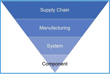
Figure 1: Layers of security in PowerEdge AMD Rome-based servers
Layer 1: AMD EPYC-based System Security for Processor, Memory and VMs on PowerEdge
The first generation of the AMD EPYC processors have the AMD Secure Processor – an independent processor core integrated in the CPU package alongside the main CPU cores. On system power-on or reset, the AMD Secure Processor executes its firmware while the main CPU cores are held in reset. One of the AMD Secure Processor’s tasks is to provide a secure hardware root-of-trust by authenticating the initial PowerEdge BIOS firmware. If the initial PowerEdge BIOS is corrupted or compromised, the AMD Secure Processor will halt the system and prevent OS boot. If no corruption, the AMD Secure Processor starts the main CPU cores, and initial BIOS execution begins.
The very first time a CPU is powered on (typically in the Dell EMC factory) the AMD Secure Processor permanently stores a unique Dell EMC ID inside the CPU. This is also the case when a new off-the-shelf CPU is installed in a Dell EMC server. The unique Dell EMC ID inside the CPU binds the CPU to the Dell EMC server. Consequently, the AMD Secure Processor may not allow a PowerEdge server to boot if a CPU is transferred from a non-Dell EMC server (and CPU transferred from a Dell EMC server to a non-Dell EMC server may not boot).
AMD EPYC Generation 2 processors also offer the AMD Secure Processor --- for cryptographic functionality for secure key generation and key management. This provides full stack encryption without any overhead for the processor. In addition, for hardware-accelerated memory encryption for data-in-use protection, the security components in Rome processors include the AES-128 encryption engine, which is embedded in the memory controller and automatically encrypts and decrypts data in main memory with an appropriate key.
The AMD EPYC processors also include these two unique security features:
Secure Memory Encryption (SME):
SME uses a single key to encrypt system memory, which is generated by the AMD Secure Processor at boot. SME requires enablement in the system BIOS or operating system; when enabled in the BIOS, memory encryption is transparent and can be run with any operating system
Secure Encrypted Virtualization (SEV):
In addition to what SME capabilities, SEV provides Virtual Machine (VM) level encryption, which protects against hypervisor corruption with hardware protection – a more robust solution than software protection. The EPYC Generation 2 (Rome) processors also offer 509 keys per hypervisor for SEV, versus 16 in EPYC (Naples)-based servers
Secure Encrypted Virtualization – Encrypted State (SEV ES):
Encrypts all CPU register contents when a VM stops running, preventing leakage of information in CPU registers to components like the hypervisor, and it can detect malicious modifications to a CPU register state. Some technical details:
- Guest register state is encrypted with guest encryption key and integrity protected
- Only the guest can modify its register state
- Guest must explicitly share register state with the hypervisor
- Guest-Hypervisor Communication Block (GHCB)
- Protects the guest register state from the hypervisor
- Adds additional protection against VM state related attacks (exfiltration, control flow, rollback)
For more information, see this technical brief on EPYC first generation security: AMD CPU Security Features in PowerEdge 14G Servers.
Layer 2: PowerEdge Systems Security
All Dell EMC PowerEdge servers offer built-in security that supports customers with compliance, preventive security, and fast means to recover in the event of errors or breaches. This includes FIPs/Common Criteria Compliance, immutable silicon root of trust (PowerEdge CPUs have a Dell signature: once it is used in a Dell system if cannot be used in another server), digitally signed firmware updates, automatic BIOS recovery, firmware rollback, and more.
In addition, Dell EMC offers differentiated security features in every PowerEdge system:
- Dell EMC OpenManage Secure Enterprise Key Manager –embedded in Dell EMC PowerEdge servers and works in conjunction with leading Key Management Servers for enabling keys at scale
- System Lockdown – Locks down the configuration and firmware, protecting the server(s) from inadvertent or malicious changes, and is enabled or disabled by the IT Administrator… and prevents system/firmware “drift”
- System erase of all user drives, including NVMe – through a process that is not only fast, but enables the drives to be reused and meets NIST recommendations for data erasure
- Rapid OS Recovery – Allows users to boot a trusted backup OS image from a hidden boot device
- Enhanced UEFI secure boot with custom certificates – with UEFI Secure Boot, each component in the chain is validated and authorized against a specific certificate before it is allowed to load or run
- Dynamically-enabled USB ports
- This feature allows administrators to disable all USB ports and then enable them dynamically to allow local crash cart usage (to let a local technician have temporary access)
- The USB ports can be dynamically enabled and disabled without rebooting the server; normally changing the USB port state requires a reboot and takes down the workloads
- Intrusion-switch included – detection of chassis intrusion at no extra expense
- Domain Isolation - an important feature for multi-tenant hosting environments, hosting providers may want to block any re-configuration by tenants. Domain isolation is a configuration option that ensures that management applications in the host OS have no access to the out-of-band iDRAC or to Intel chipset functions
For more information, see this technical brief: Security in Server Design
And this video for further information:
Server Security – Dell EMC PowerEdge Servers
Layer 3: Dell Technologies Factory Security
Factories where Dell products are built must meet specified Transported Asset Protection Association (TAPA) facility security requirements, including the use of closed-circuit cameras in key areas, access controls, and continuously guarded entries and exits. Additional controls are applied at Dell and supplier- managed facilities and for air, rail, and ocean shipments to address the variety of risks faced across transportation modes and regions. Some of these protections include tamper-evident packaging, security reviews of shipping lanes, locks or hardware meeting required specifications, and container integrity requirements. GPS tracking devices may also be placed on any container and monitored 24x7 until confirmation of delivery.
Dell also maintains certification with the United States Customs and Border Patrol’s Customs-Trade Partnership Against Terrorist (C-TPAT). This logistics security program is recognized as compatible with similar programs around the world, including the Authorized Economic Operator (AEO), Canada’s Supply Chain Assurance v4.0 | Dell Inc., 2018 4 Partners in Protection, and Singapore’s Secure Trade Partnership programs. While the primary focus of these programs is to prevent contraband, the required protections also guard against tampering with products being imported.
Layer 4: Dell Technologies Supply Chain Security
The goal of Dell’s supply chain security processes is to provide continuous security risk assessment and improvement. Dell’s Supply Chain Risk Management framework mirrors that of the comprehensive risk management framework of the National Infrastructure Protection Plan (NIPP), which outlines how government and the private sector can work together to mitigate risks and meet security objectives. Dell’s framework incorporates an open feedback loop (see Figure 2) that allows for continuous improvement.
Risk mitigation plans are prioritized and implemented as appropriate throughout the entire solution life cycle.
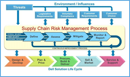
Figure 2 Managing the supply chain for Dell Technologies products
The process includes these safeguards by Dell Technologies for the supply chain:
- Supplier governance by Dell
- Audits
- Global Inventory Control Policy
- Measure suppliers’ security practices against industry best practices for physical security and for mitigating counterfeit components, tainted software and firmware, and intellectual property theft
- Quarterly Reviews
- Supply Chain Security
- Physical (factory/manufacturing) – factories where Dell products are built must meet specified Transported Asset Protection Association (TAPA) facility security requirements. Dell also maintains certification with the United States Customs and Border Patrol’s Customs-Trade Partnership Against Terrorist (C-TPAT).
- Personnel – Dell policy requires employees throughout the supply chain, including those at contract suppliers, to go through a pre-employment suitability screening process.
- Information – Dell collects and uses sensitive information about products, solutions, customers, suppliers and partners throughout the supply chain lifecycle. Dell uses numerous measures to guard this sensitive information against exposure and exploitation.
- Supply Chain Integrity
Dell has developed baseline specifications that are securely preserved and later used as a reference to verify that no unauthorized modifications have been made to hardware or software. The goal is to ensure that the products received by customers are the products customers expected and will operate as intended.
For hardware, this includes processes to minimize the opportunity for counterfeit components to infiltrate our supply chain. For software, Industry software engineering best practices include security throughout the development process for any code, including operating systems, applications, firmware, and device drivers. Dell reduces opportunities for the exploitation of software security flaws by incorporating Secure Development Lifecycle (SDL) measures throughout the development process. These measures are tightly aligned with Software Assurance Forum for Excellence in Code (SAFECode) guidelines and ISO 27034.
- Stronger together
Dell participates in supply chain risk management activities with trusted industry groups and public/private partnerships. Dell has been actively engaged in the Open Group Trusted Technology Forum (O-TTPF), the Software and Supply Chain Assurance Forum, SAFECode, the Supply Chain Risk Leadership Council, the Internet Security Alliance, and the IT Sector Coordinating Council. Dell is also an active member of the Government Information Data Exchange Program (GIDEP). Dell has participated in the development of numerous standards and best-practice guidelines related to supply chain integrity including the Open Group Trusted Technology Provider Standard (O-TTPS) which is also recognized as ISO 20243, SAFECode, ISO 27036, and National Institute of Science and Supply Chain Assurance v4.0 | Dell Inc., 2018 6 Technology (NIST) Interagency Report (IR) 7622, NIST Special Publication (SP) 800-161, NIST SP800-53, and the NIST Cybersecurity Framework. To address customer concerns about product tampering and supply chain assurance, Dell continues to monitor and influence the development and potential impact of legislation, regulations, voluntary standards, and contract language
For more details on Dell supply chain security please refer to this white paper: https://i.dell.com/sites/csdocuments/CorpComm_Docs/en/supply-chain-assurance.pdf?newtab=true
In Conclusion
Security must be designed within the architecture of the server to effectively withstand sophisticated cyber - crime: phishing attacks that harvest credentials, advanced persistent threats (taking control of firmware), data exfiltration (stealing data). Yet it’s not just the server features that need to support customer security – it is also necessary to provide protection against the possibility of corruption in manufacturing and within the server supply chain. These layers of security must be considered as critical criteria for user decisions on integrating technical equipment into their environments.
As Dell EMC designs products, it will always be to protect, protect, and protect customer data and assets – and in consideration of worst-case scenarios, ensure that users of Dell EMC solutions can recover quickly, and resume production with as little disruption as possible. With these goals, Dell EMC is constantly evaluating new ways within each security layer to protect customers.
Related Documents

Improve performance by easily migrating to a modern OpenShift environment on PowerEdge R7615 servers
Tue, 14 May 2024 20:15:19 -0000
|Read Time: 0 minutes
Improve performance and gain room to grow by easily migrating to a modern OpenShift environment on Dell PowerEdge R7615 servers with 4th Generation AMD EPYC processors and high-speed 100GbE Broadcom NICs
We deployed this modern environment, then migrated database VMs from legacy servers and saw performance improvements that support consolidation.

Transactional databases are the backbone of many business operations, powering ecommerce and order fulfillment, human resources and payroll, and a host of other activities. If your company is running these kinds of workloads on server infrastructure that is several years old, you might believe that performance is adequate and that you have little reason to consider upgrading to new servers with modern processors, networking, and a Red Hat® OpenShift® container-based environment. In fact, by continuing to use this older gear, you could be incurring higher than necessary operating expenditures by maintaining and powering more servers than you need to perform a given volume of work. You could also be risking downtime with aging hardware that is likelier to break down. By upgrading to a modern environment, you could mitigate these issues and future-proof your infrastructure. A 2019 Forrester Consulting report recommended that organizations refresh their servers at least every three years to maximize agility and productivity.[1] The report states not only that modern servers allow organizations to adopt more emerging technologies at a faster rate, but also “modern hardware has a profound impact on business benefits such as better customer experience, employee productivity, and innovation.”[2]
We explored the process of migrating VMs from a legacy environment and conducted testing to quantify the resulting improvements in network and database performance. We started with a legacy environment consisting of MySQL™ virtual machines (VMs) running on a cluster of three Dell™ PowerEdge™ R7515 servers with 3rd Generation AMD EPYC™ processors and 25Gb Broadcom® NICs. We then deployed a modern OpenShift container-based environment comprising three Dell PowerEdge R7615 servers with 4th Generation AMD EPYC processors and high-speed 100Gb Broadcom NICs. While the primary application of OpenShift is typically for containerized workloads, we used OpenShift Virtualization, which presents a familiar VM layer to administrators while utilizing the containerized technology on the underlying layer. Both environments used a Dell PowerStore 1200T for external storage that the servers accessed using iSCSI. We measured database performance using the HammerDB TPROC-C benchmark.
We found that the modern cluster environment of Dell PowerEdge R7615 servers with 4th Generation AMD EPYC processors and high-speed 100Gb Broadcom NICs outperformed the legacy cluster environment, delivering 44 percent greater database performance. These improvements mean that companies that upgrade can enjoy savings by meeting their workload requirements with fewer servers to license, maintain, power, and cool. Selecting 100Gb Broadcom NICs also positions companies well to take advantage of increasingly popular network-intensive technologies such as artificial intelligence (AI).
The benefits of containerization and Red Hat OpenShift Virtualization
Many organizations choose containers for DevOps due to their easy scalability and portability. Because a container encapsulates an application as well as everything necessary to run that application, it’s simple to move the container from development to test and production environments, adding instances of the application by replicating the container. Containers can also be useful for microservices, data streaming, and other use cases.[3]
Containers aren’t necessarily ideal for every use case, however, and for some infrastructures, IT teams may wish to incorporate both containers and VMs. Red Hat OpenShift Virtualization, which we used in our testing, enables organizations to run both VMs and containers on the same platform by bringing VMs into containers.[4] This lets IT reap the benefits of both containers and VMs with the efficiency benefit of relying on one management tool, rather than having to maintain two distinct infrastructures.
About our testing
We explored the process of deploying a modern data center environment and migrating VMs to it from a legacy environment. We also measured the database performance the VMs achieved in both environments:
Legacy environment
- Three Dell PowerEdge R7515 servers with 3rd Generation AMD EPYC 7663 56-core processors and Broadcom Advanced Dual 25Gb Ethernet NICs
- External storage using Dell PowerStore 1200T over iSCSI
- VMware® vSphere® 8
Modern environment
- Three Dell PowerEdge R7615 servers with 4th Generation AMD EPYC 9554 64-core processors and Broadcom NetExtreme-E BCM57508 100GB NICs
- External storage using Dell PowerStore 1200T over iSCSI
- Red Hat OpenShift 4.14
Figure 1 presents a diagram of our test configuration. In addition to our test server clusters, we needed three servers to host infrastructure VMs, workload client VMs, and the OpenShift control node VMs. We configured a Dell PowerEdge R7525 to serve as the host for our infrastructure VMs for services such as AD, DHCP, and DNS, as well as HammerDB client VMs. We also configured a Dell PowerEdge R7625 to host additional HammerDB client VMs. For the OpenShift environment, we deployed a Dell PowerEdge R540 to host the OCP control nodes. We virtualized the control nodes to reduce the number of servers needed for the test bed.
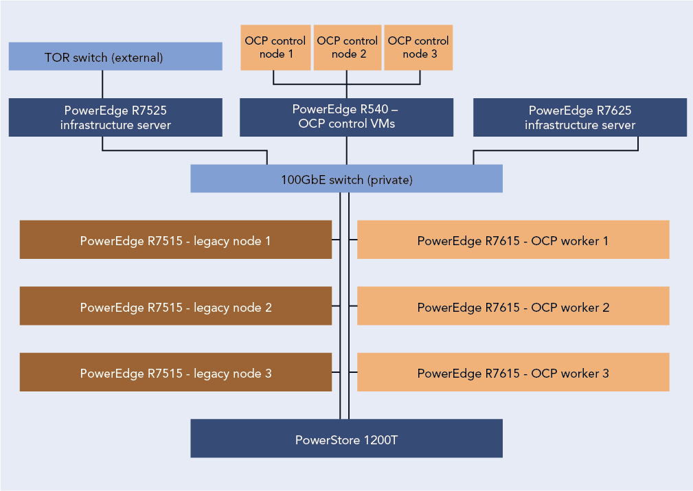
Figure 1: Our test configuration. Source: Principled Technologies.
To test the MySQL database performance of each environment, we used the TPROC-C workload from the HammerDB benchmark. HammerDB developers derived their OLTP workload from the TPC-C benchmark specifications; however, as this is not a full implementation of the official TPC-C standards, the results in this paper are not directly comparable to published TPC-C results. For more information, please visit https://www.hammerdb.com/docs/ch03s01.html.
Each VM had a single MySQL instance with a TPROC-C database. We targeted the maximum transactions per minute (TPM) each environment could achieve by increasing the user count until performance degraded.
What we learned
Finding 1: Deploying OpenShift in the modern environment was easy
For our environment, the OpenShift installation process using the Red Hat Assisted Installer to install an OpenShift Installer-Provisioned Cluster was straightforward and simple. We started by setting up the prerequisites for the environment, which included a VM for Active Directory, DNS, and DHCP. We created a domain for our private network and added the API and ingress routes as DNS A records. Next, we set up a VM as a router so that our OpenShift environment could access the internet from our private network. Finally, we created three blank VMs to serve as our OpenShift controller nodes. Once we had met the pre-requisite requirements, we logged into the Red Hat Hybrid Console and navigated to the Assisted Installer to create the cluster.
The Assisted Installer streamlined the process by walking us through configuration menus for storage, network, and access to the cluster. We started the cluster creation by assigning it a name, providing the domain, and selecting an OpenShift version. From there the installer guided us through the process of providing an installer image using the SSH public key of the server running the installer. After downloading the ISO, we booted each of the controller and worker nodes into the image and the Assisted Installer discovered each node. After discovering the controller and worker nodes, the installer walked us through the rest of the configuration process and then began the installation. The Assisted Installer made the process very simple with only six configuration tabs to advance through, and with our total install time after configuration taking around three hours. Once the installation was complete, each node rebooted into the OpenShift OS and the Assisted Installer provided us with a cluster console fully qualified domain name (FQDN) to connect to and manage the cluster from. For detailed steps on the OpenShift deployment process, see the science behind the report.
Finding 2: Migrating VMs from the legacy VMware environment to the modern OpenShift environment was easy
Migrating a VM from the VMware environment to OpenShift was also a straightforward process and quick to set up. While the actual migration time will vary depending on VM size and hardware speed, the setup consists of only a few steps and took us less than 10 minutes. We first installed the Migration Toolkit for Virtualization from the OpenShift OperatorHub. We then entered the IP address and credentials for the vCenter as a new provider. Next, we created a NetworkMap and a StorageMap to connect the respective resources between the environments. We then created a new migration plan to map the VMs to a namespace in OCP. We ran the migration plan on a single VM, and confirmed that we were able to enter the VM console once the migration was complete. For detailed steps on the process of migrating VMs from the legacy environment to the modern environment, see the science behind the report.
About 4th Gen AMD EPYC 9554 processors
According to AMD, EPYC 9554 processors deliver fast performance “for cloud, enterprise, and HPC workloads—helping accelerate your business.”[5] EPYC processors include AMD Infinity Guard, which per AMD is “a set of layered, cutting-edge security features that help you protect sensitive data and avoid the costly downtime cause by security breaches.”[6]
In addition to performance and security features, AMD claims their processors are energy-efficient, which can reduce energy costs and “minimize environmental impacts from data center operations while advancing your company’s sustainability objectives.”[7]
When comparing SPECCPU Floating Point peak rates and the default thermal design power (TDP) of the AMD EPYC 9554 and the AMD EPYC 7663, the 9554 has 54 percent better performance per watt, which demonstrates the improved power efficiency with the new 4th Gen AMD EPYC process.[8],[9]
For more information about 4th Gen AMD EPYC processors visit: https://www.amd.com/en/processors/epyc-server-cpu-family.
Finding 3: Database performance improved by 44 percent in the new environment
Figure 2 shows the results of our database performance testing using the TPROC-C workload from the HammerDB benchmark suite. The modern OpenShift cluster of Dell PowerEdge R7615 servers outperformed the legacy cluster by 44 percent. This extra capability could benefit companies upgrading to the new environment in several ways. The company could provide a better user experience, perform more work—or support more users—with a given number of servers, or reduce the number of servers necessary to execute a given workload.

Figure 2: Performance in transactions per minute using the TPROC-C workload of the HammerDB benchmark suite. Higher is better. Source: Principled Technologies.
Finding 4: Performance improved in the modern cluster, supporting consolidation, which leads to savings
Based on the results of our performance tests (see Figure 3), a company could consolidate the database workloads of a four-node Dell PowerEdge 7515 cluster with some additional headroom into three modern Dell PowerEdge R7615 servers with 4th Generation AMD EPYC processors and high-speed 100Gb Broadcom NICs.
The cluster of three modern servers delivered a total of 9,674,180 transactions per minute (3,224,726 TPMs per server). The cluster of three legacy servers delivered a total of 6,714,712 TPM (2,238,237 per server). Based on these results, four legacy servers would achieve a total of 8,952,948 TPM, which would leave 721,231 additional TPM room for growth on the modern three-node cluster.
Reducing the number of servers you need means that operational expenditures such as data center power and cooling and administrator time for maintenance also decrease, leading to ongoing savings.

Figure 3: Performance in transactions per minute that three modern servers and four legacy servers could achieve, based on our hands-on testing. Higher is better. Source: Principled Technologies.
About Dell PowerEdge R7615 servers
The Dell PowerEdge R7615 is a 2U, single-socket rack server. Dell states that it has designed this server to provide “performance and flexible, low-latency storage options in an air or Direct Liquid Cooling (DLC) configuration.”[10]
According to Dell, this server uses the AMD EPYC 4th generation processor to deliver up to 50 percent higher core count per single-socket platform in an innovative air-cooled chassis.[11] It also supports DDR5 at 4800 MT/s memory and PCIe® Gen5 with double the speed of previous Gen4 for faster access and transport of data, optimizing application output.[12] It supports up to six single-wide full-length GPUs or three double-wide full-length GPUs, to improve responsiveness or reduce app load time for power users, plus lower-latency, high-performance NVMe SSDs to help maximize compute performance.[13]
Learn more at https://www.delltechnologies.com/asset/en-us/products/servers/technicalsupport/poweredge-r7615-spec-sheet.pdf.
How high-speed 100Gb Broadcom NICs can help your organization
Even if a 25Gb NIC is sufficient to meet a company’s current networking needs, opting to equip new servers with the high-speed 100Gb Broadcom NIC can be a smart move. Future-proofing your network can allow you to meet the increasing demands of emerging technologies.
Advanced technologies such as artificial intelligence and machine learning, which can require the processing and transmission of large amounts of data, are becoming increasingly prevalent across businesses of all sizes. In a June 2023 survey of small business decision-makers, 74 percent were interested in using AI or automation in their business and 55 percent said their interest in these technologies had grown in the first half of 2023.[14] Upgrading to a modern environment with a highspeed 100Gb Broadcom NIC positions companies to take advantage of AI applications for social media, content creation, marketing, customer support, and many other use cases.
Another way that investing in the high-speed 100Gb Broadcom NIC can help your company is through improved efficiency. You might be tempted to go with a 25Gb NIC, thinking that as your networking needs increase, you can simply add more NICs of this size. However, consider a 2023 Principled Technologies study that compared the performance of a server solution with a 100Gb Broadcom 57508 NIC and a solution with four 25Gb NICs.[15] Testing revealed that the 100Gb NIC solution achieved up to 2.3 times the throughput of the solution with 25Gb NICs. It also delivered greater bandwidth consistency, which can translate to providing a better user experience; the report states that applications using the 25Gb NICs network configuration “would experience significant variation in available bandwidth, potentially causing jittery or interrupted service to multiple streams.”[16]
About the Broadcom BCM57508-P2100G Dual-Port 100GbE PCle 4.0 ethernet controller
A higher performing NIC can reduce latency, increase throughput, and allow the server to transmit and receive a great volume of data. The Dell PowerEdge R7615 we tested features the Broadcom BCM57508-P2100G DualPort 100GbE PCle 4.0 ethernet controller, which supports speeds of up to 200 Gigabits per second. Broadcom designed the BCM57508-P2100G “to build highlyscalable, feature-rich networking solutions in servers for enterprise and cloud-scale networking and storage applications, including high-performance computing, telco, machine learning, storage disaggregation, and data analytics.”[17]
The BCM57508-P2100G features BroadSAFE® technology, “to provide unparalleled platform security” and a “unique set of highly-optimized hardware acceleration engines to enhance network performance and improve server efficiency.”[18]
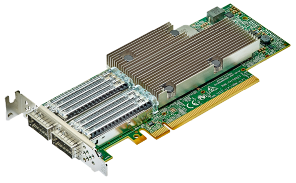 BCM57508-P2100G Dual-Port 100GbE PCle 4.0 ethernet controller. Image provided by Dell.
Conclusion
If your organization’s transactional databases are running on gear that is several years old, you have much to gain by upgrading to modern servers with new processors and networking components and an OpenShift environment. In our testing, a modern OpenShift environment with a cluster of three Dell PowerEdge R7615 servers with 4th Generation AMD EPYC processors and high-speed 100Gb Broadcom NICs outperformed a legacy environment with MySQL VMs running on a cluster of three Dell PowerEdge R7515 servers with 3rd Generation AMD EPYC processors and 25Gb Broadcom NICs. We also easily migrated a VM from the legacy environment to the modern environment, with only a few steps required to set up and less than ten minutes of hands-on time. The performance advantage of the modern servers would allow a company to reduce the number of servers necessary to perform a given amount of database work, thus lowering operational expenditures such as power and cooling and IT staff time for maintenance. The high-speed 100Gb Broadcom NICs in this solution also give companies better network performance and networking capacity to grow as they embrace emerging technologies such as AI that put great demands on networks.
This project was commissioned by Dell Technologies.
May 2024
Principled Technologies is a registered trademark of Principled Technologies, Inc.
All other product names are the trademarks of their respective owners.
Read the report on the PT site at https://facts.pt/2V6p3FG and see the science at https://facts.pt/Dj53ZJb.
Author: Principled Technologies
[1] Forrester, “Why Faster Refresh Cycles and Modern Infrastructure Management are Critical to Business Success,” accessed May 1, 2024, www.techrepublic.com/resource-library/casestudies/forrester-why-faster-refresh-cycles-and-modern-infrastructure-management-are-critical-to-business-success/.
[2] Forrester, “Why Faster Refresh Cycles and Modern Infrastructure Management are Critical to Business Success,” accessed May 1, 2024, www.techrepublic.com/resource-library/casestudies/forrester-why-faster-refresh-cycles-and-modern-infrastructure-management-are-critical-to-business-success/.
[3] Red Hat, “Understanding containers,” accessed April 12, 2024, https://www.redhat.com/en/topics/containers.
[4] Red Hat, “Red Hat OpenShift Virtualization,” accessed April 12, 2024,
https://www.redhat.com/en/technologies/cloud-computing/openshift/virtualization.
[5] AMD, “AMD EPYC Processors,” accessed April 12, 2024, https://www.amd.com/en/processors/epyc-server-cpu-Family.
[6] AMD, “AMD EPYC Processors.”
[7] AMD, “AMD EPYC Processors.”
[8] SPEC, “SPEC CPU®2017 Floating Point Rate Result for Dell PowerEdge R6615 (AMD EPYC 9554 64-Core Processor),” accessed May 2, 2024, https://www.spec.org/cpu2017/results/res2024q1/cpu2017-20240212-41481.html.
[9] SPEC, “SPEC CPU®2017 Floating Point Rate Result for Dell PowerEdge R6515 (AMD EPYC 7663 56-Core Processor),” accessed May 2, 2024, https://www.spec.org/cpu2017/results/res2021q3/cpu2017-20210913-29288.html.
[10] Dell, “PowerEdge R7615 Specification Sheet,” accessed April 12, 2024, https://www.delltechnologies.com/asset/en-us/products/servers/technical-support/poweredge-r7615-spec-sheet.pdf.
[11] Dell, “PowerEdge R7615 Specification Sheet.”
[12] Dell, “PowerEdge R7615 Specification Sheet.”
[13] Dell, “PowerEdge R7615 Specification Sheet.”
[14] Constant Contact, “AI Stats and Trends Small Businesses Need to Know Now,” accessed April 12, 2024, https://news.constantcontact.com/small-business-now-ai-2023.
[15] Principled Technologies, “Opt for modern 100Gb Broadcom 57508 NICs in your
Dell PowerEdge R750 servers for improved networking performance,” accessed April 12, 2024,
https://www.principledtechnologies.com/Dell/PowerEdge-R750-networking-iPerf-1023.pdf.
[16] Principled Technologies, “Opt for modern 100Gb Broadcom 57508 NICs in your
Dell PowerEdge R750 servers for improved networking performance,” accessed April 12, 2024,
https://www.principledtechnologies.com/Dell/PowerEdge-R750-networking-iPerf-1023.pdf.
[17] Broadcom, “BCM57508 – 200GbE,” accessed April 12, 2024,
https://www.broadcom.com/products/ethernet-connectivity/network-adapters/bcm57508-200g-ic.
[18] Broadcom, “BCM57508 – 200GbE.”

Dell PowerEdge 16G Server BIOS Settings for Optimized Performance: R7625, R6625, R7615, R6615, C6615
Tue, 26 Mar 2024 22:46:05 -0000
|Read Time: 0 minutes
BIOS setting recommendations
The following tables provide the BIOS setting recommendations for the latest generation of PowerEdge servers:
Table 1. BIOS setting recommendations - System profile settings
| System setup screen | Setting | BIOS Defaults | SPEC cpu2017 int rate (General Purpose Performance) | SPEC cpu2017 fp rate | SPEC cpu2017 int speed | SPEC cpu2017 fp speed | Memory Throughput | HPC | Latency |
| System profile setting | System profile | Performance Per Watt | Custom | Custom | Custom | Custom | Custom | Custom | Custom |
| System profile setting[*] | CPU Power Management | OS DBPM | OS DBPM | OS DBPM | OS DBPM | OS DBPM | OS DBPM | Max Performance | Max Performance |
| System profile setting | Memory Frequency | Max Performance | Max Performance | Max Performance | Max Performance | Max Performance | Max Performance | Max Performance | Max Performance |
| System profile setting | Turbo Boost | Enabled | Enabled | Enabled | Enabled | Enabled | Enabled | Enabled | Enabled |
| System profile setting | C-States | Enabled | Enabled | Enabled | Disabled | Disabled | Disabled | Disabled | Disabled |
| System profile setting | Write Data CRC | Disabled | Disabled | Disabled | Disabled | Disabled | Disabled | Enabled | Disabled |
| System profile setting | Memory Patrol Scrub | Standard | Disabled | Disabled | Disabled | Disabled | Disabled | Disabled | Disabled |
| System profile setting | Memory Refresh Rate | 1x | 1x | 1x | 1x | 1x | 1x | 1x | 1x |
| System profile setting | Workload Profile | not configured | not configured | not configured | not configured | not configured | not configured | HPL | not configured |
| System profile setting | PCI ASPM L1 Link Power Management | Enabled | Disabled | Disabled | Disabled | Disabled | Disabled | Disabled | Disabled |
| System profile setting | Determinism Slider | Performance Determinism | Power Determinism | Power Determinism | Power Determinism | Power Determinism | Power Determinism | Power Determinism | Power Determinism |
| System profile setting | Power Profile Select | High Performance Mode | High Performance Mode | High Performance Mode | High Performance Mode | High Performance Mode | High Performance Mode | High Performance Mode | High Performance Mode |
| System profile setting | PCIE Speed PMM Control | Auto | Auto | Auto | Auto | Auto | Auto | Auto | (GEN 5) |
| System profile setting | EQ Bypass To Highest Rate | Disabled | Disabled | Disabled | Disabled | Disabled | Disabled | Disabled | Disabled |
| System profile setting | DF PState Frequency Optimizer | Enabled | Enabled | Enabled | Enabled | Enabled | Enabled | Enabled | Enabled |
| System profile setting | DF PState Latency Optimizer | Enabled | Enabled | Enabled | Enabled | Enabled | Enabled | Enabled | Enabled |
| System profile setting | DF CState | Enabled | Enabled | Enabled | Enabled | Enabled | Enabled | Enabled | Enabled |
| System profile setting | Host System Management Port (HSMP) Support | Enabled | Enabled | Enabled | Enabled | Enabled | Enabled | Enabled | Enabled |
| System profile setting | Boost FMax | 0-Auto | 0-Auto | 0-Auto | 0-Auto | 0-Auto | 0-Auto | 0-Auto | 0-Auto |
| System profile setting | Algorithm Performance Boost Disable (ApbDis) | Disabled | Disabled | Disabled | Enabled | Enabled | Disabled | Disabled | Enabled |
| System profile setting | ApbDis Fixed Socket P-State[2] | P0 | P0 | P0 | |||||
| System profile setting | Dynamic Link Width Management (DLWM) | Unforced | Unforced | Unforced | Unforced | Unforced | Unforced | Unforced | Forced x16 |
[*] For C6615, apply setting from Table 3.
[1] Depends on how system was ordered. Other System Profile defaults are driven by this choice and may be different than the examples listed. Select Performance Profile first, and then select Custom to load optimal profile defaults for further modification.
[2] Pstate field is dependent on Algorithm Performance Boost Disable (ApbDis) and is visible only when it is enabled.
Table 2. BIOS setting recommendations – Memory, processor, and iDRAC settings
| System setup screen | Setting | BIOS Defaults | SPEC cpu2017 int rate (General Purpose Performance) | SPEC cpu2017 fp rate | SPEC cpu2017 int speed | SPEC cpu2017 fp speed | Memory Throughput | HPC | Latency |
| Memory settings | System Memory Testing | Disabled | Disabled | Disabled | Disabled | Disabled | Disabled | Disabled | Disabled |
| Memory settings | DRAM Refresh Delay | Minimum | Performance | Performance | Performance | Performance | Performance | Performance | Performance |
| Memory settings | Correctable memory ECC SMI | Enabled | Disabled | Disabled | Disabled | Disabled | Disabled | Disabled | Disabled |
| Memory settings | Uncorrectable Memory Error (DIMM Self healing on uncorrectable memory) | Enabled | Disabled | Disabled | Disabled | Disabled | Disabled | Disabled | Disabled |
| Memory settings | Correctable Error Logging | Disabled | Disabled | Disabled | Disabled | Disabled | Disabled | Disabled | Disabled |
| Processor settings | Logical Processor | Enabled | Enabled | Disabled[1] | Disabled[1] | Disabled[1] | Disabled[1] | Disabled[1] | Disabled[1] |
| Processor settings | Virtualization Technology | Enabled | Disabled | Disabled | Disabled | Disabled | Disabled | Disabled | Disabled |
| Processor settings | IOMMU Support | Enabled | Enabled | Enabled | Enabled | Enabled | Enabled | Enabled | Enabled |
| Processor settings | Kernel DMA Protection | Disabled | Disabled | Disabled | Disabled | Disabled | Disabled | Disabled | Disabled |
| Processor settings | L1 Stream HW Prefetcher | Enabled | Enabled | Disabled | Enabled | Enabled | Enabled | Enabled | Enabled |
| Processor settings | L2 Stream HW Prefetcher | Enabled | Enabled | Enabled | Enabled | Enabled | Enabled | Enabled | Enabled |
| Processor settings | L1 Stride Prefetcher | Enabled | Enabled | Enabled | Enabled | Enabled | Enabled | Enabled | Enabled |
| Processor settings | L1 Region Prefetcher | Enabled | Enabled | Enabled | Enabled | Enabled | Enabled | Enabled | Enabled |
| Processor settings | L2 Up Down Prefetcher | Enabled | Enabled | Enabled | Enabled | Enabled | Enabled | Enabled | Enabled |
| Processor settings | MADT Core Enumeration | Linear | Linear | Linear | Linear | Linear | Linear | Linear | Linear |
| Processor settings[*] | NUMA Node Per Socket | 1 | 4 | 4 | 4 | 1 | 4 | 4 | 4 |
| Processor settings | L3 cache as NUMA | Disabled | Disabled | Disabled | Disabled | Disabled | Disabled | Disabled | Disabled |
| Processor settings | Secure Memory Encryption | Disabled | Disabled | Disabled | Disabled | Disabled | Disabled | Disabled | Disabled |
| Processor settings | Minimum SEV no-ES ASID | 1 | 1 | 1 | 1 | 1 | 1 | 1 | 1 |
| Processor settings | SNP Memory Coverage | Disabled | Disabled | Disabled | Disabled | Disabled | Disabled | Disabled | Disabled |
| Processor settings | Secure Nested Paging | Disabled | Disabled | Disabled | Disabled | Disabled | Disabled | Disabled | Disabled |
| Processor settings | Transparent Secure Memory Encryption | Disabled | Disabled | Disabled | Disabled | Disabled | Disabled | Disabled | Disabled |
| Processor settings | ACPI CST C2 Latency | 800 | 18 | 18 | 18 | 18 | 800 | 18 | 800 |
| Processor settings | Configurable TDP | Maximum | Maximum | Maximum | Maximum | Maximum | Maximum | Maximum | Maximum |
| Processor settings | x2APIC Mode | Enabled | Enabled | Enabled | Enabled | Enabled | Enabled | Enabled | Enabled |
| Processor settings | Number of CCDs per Processor | All | All | All | All | All | All | All | All |
| Processor settings | Number of Cores per CCD | All | All | All | All | All | All | All | All |
| iDRAC settings | Thermal Profile | Default | Maximum Performance | Maximum Performance | Maximum Performance | Maximum Performance | Maximum Performance | Maximum Performance | Maximum Performance |
[*] For C6615, apply setting from Table 3.
[1] Logical Processor (Hyper Threading) tends to benefit throughput-oriented workloads such as SPEC CPU2017. Many HPC workloads disable this option.
Table 3. BIOS setting recommendations specific to C6615 (apply remaining settings from Table 1 and 2)
System setup screen | Setting | BIOS Defaults | SPEC cpu2017 int rate (General Purpose Performance) | SPEC cpu2017 fp rate | SPEC cpu2017 int speed | SPEC cpu2017 fp speed | Memory Throughput | HPC | Latency |
Processor settings | NUMA Node per Socket | 1 | 1 | 1 | 1 | 1 | 2 | 1 | 2 |
System profile setting | CPU Power Management | OS DBPM | OS DBPM | OS DBPM | OS DBPM | OS DBPM | OS DBPM | OS DBPM | OS DBPM |
iDRAC recommendations
Following are what we would recommend for an iDRAC environment:
- Thermally challenged environments should increase fan speed through iDRAC Thermal Section.
- All Power Capping should be removed in performance-sensitive environments.
Glossary
System profile: (Default="Performance Per Watt")
To assist the average customer in setting each individual power/performance feature for their specific environment, a menu option is provided that can help a customer optimize the system for factors such as minimum power usage/acoustic levels, maximum efficiency, Energy Star optimization, and maximum performance.
Performance Per Watt OS mode optimizes the performance/watt efficiency with a bias towards performance. It is the favored mode for Energy Star. Note that this mode is slightly different than Performance Per Watt DAPC mode. In this mode, no bus speeds are derated, leaving the OS in charge of making those changes.
Custom allows the user to individually modify any of the low-level settings that are preset and unchangeable in any of the other four preset modes.
C-States
C-states reduce CPU idle power. There are three options in this mode: Legacy, Autonomous, and Disable.
Enabled: When “Enabled” is selected, the operating system initiates the C-state transitions. Some OS SW may defeat the ACPI mapping, such as intel_idle driver.
Autonomous: When "Autonomous" is selected, HALT and C1 requests get converted to C6 requests in hardware.
Disable: When "Disable" is selected, only C0 and C1 are used by the OS. C1 gets enabled automatically when an OS autohalts.
CPU Power Management
CPU Power Management allows the selection of CPU power management methodology. Maximum Performance is typically selected for performance-centric workloads where it is acceptable to consume additional power to achieve the highest possible performance for the computing environment. This mode drives processor frequency to the maximum across all cores (although idled cores can still be frequency-reduced by C-States enforcement through BIOS or OS mechanisms if enabled). This mode also offers the lowest latency of the CPU Power Management Mode options, so it is always preferred for latency-sensitive environments. OS DBPM is another Performance Per Watt option that relies on the operating system to dynamically control individual core frequency. Both Windows and Linux can take advantage of this mode to reduce the frequency of idled or underutilized cores in order to save power. This will be Read-only unless System Profile is set to Custom.
Memory Frequency
Memory Frequency governs the BIOS memory frequency. The variables that govern maximum memory frequency include the maximum rated frequency of the DIMMs, the DIMMs per channel population, the processor choice, and this BIOS option. Additional power savings can be achieved by reducing the memory frequency at the expense of reduced performance. This will be Read-only unless System Profile is set to Custom.
Turbo Boost
Turbo Boost governs the Boost Technology. This feature allows the processor cores to be automatically clocked up in frequency beyond the advertised processor speed. The amount of increased frequency (or 'turbo upside') one can expect from an EPYC processor depends on the processor model, thermal limitations of the operating environment, and in some cases power consumption. In general terms, the fewer cores being exercised with work, the higher the potential turbo upside. The potential drawbacks for Boost are mainly centered on increased power consumption and possible frequency jitter that can affect a small minority of latency-sensitive environments. This will be Read-only unless System Profile is set to Custom.
Memory Patrol Scrub
Memory Patrol Scrubbing searches the memory for errors and repairs correctable errors to prevent the accumulation of memory errors. When set to Disabled, no patrol scrubbing will occur. When set to Standard Mode, the entire memory array will be scrubbed once in a 24-hour period. When set to Extended Mode, the entire memory array will be scrubbed more frequently to further increase system reliability. This will be Read-only unless System Profile is set to Custom.
Memory Refresh Rate
The memory controller will periodically refresh the data in memory. The frequency at which memory is normally refreshed is referred to as 1X refresh rate. When memory modules are operating at a higher-than-normal temperature or to further increase system reliability, the refresh rate can be set to 2X, however this may have a negative impact on memory subsystem performance under certain circumstances. This will be Read-only unless System Profile is set to Custom.
PCI ASPM L1 Link Power Management
When enabled, PCIe Advanced State Power Management (ASPM) can reduce overall system power while slightly reducing system performance.
Note: Some devices may not perform properly (they may hang or cause the system to hang) when ASPM is enabled; for this reason, L1 will only be enabled for validated qualified cards.
Determinism Slider
The Determinism Slider controls whether BIOS will enable determinism to control performance.
Performance Determinism: BIOS will enable 100% deterministic performance control.
Power Determinism: BIOS will not enable deterministic performance control.
Power Profile Select
High Performance Mode (default): Favors core performance. All DF P-States are available in this mode, and the default DF P-State and DLWM algorithms are active.
Efficiency Mode: Configures the system for power efficiency. Limits boost frequency available to cores and restricts DF P-States available in the system. Maximum IO.
Performance Mode: Sets up Data Fabric to maximize IO sub-system performance.
Algorithm Performance Boost Disable (ApbDis)
When enabled, a specific hard-fused Data Fabric (SoC) P-state is forced for optimizing workloads sensitive to latency or throughput. For higher performance and power savings, when disabled, P-states will be automatically managed by the Application Power Management, allowing the processor to provide maximum performance while remaining within a specified power-delivery and thermal envelope.
ApbDis Fixed Socket P-State
This value defines the forced P-state when ApbDis is enabled.
Dynamic Link Width Management (DLWM)
DLWM reduces the XGMI link width between sockets from x16 to x8 (default) when no traffic is detected on the link. As with Data Fabric and Memory P-states, this feature is optimized to trade power between core and high IO/memory bandwidth workloads.
Forced: Force link width to x16, x8, or x2.
Unforced: Link width will be managed by DLWM engine.
System Memory Testing
System Memory Testing indicates whether or not the BIOS system memory tests are conducted during POST. When set to Enabled, memory tests are performed.
Note: Enabling this feature will result in a longer boot time. The extent of the increased time depends on the size of the system memory.
Dram Refresh Delay
By enabling the CPU memory controller to delay running the REFRESH commands, you can improve the performance for some workloads. By minimizing the delay time, it is ensured that the memory controller runs the REFRESH command at regular intervals. For Intel-based servers, this setting only affects systems configured with DIMMs which use 8 Gb density DRAMs.
Correctable Memory ECC SMI
Allows the system to log ECC-corrected DRAM errors into the SEL log. Logging these rare errors can help identify marginal components, however the system will pause for a few milliseconds after an error while the log entry is created. Latency-conscious customers may want to disable the feature. Spare Mode and Mirror mode require this feature to be enabled.
DIMM Self Healing (Post Package Repair) on Uncorrectable Memory Error Enable/Disable Post Package Repair (PPR) on Uncorrectable Memory Error.
Correctable Error Logging
Enable/Disable logging of correctable memory threshold error.
Logical Processor
Each processor core supports up to two logical processors. When set to Enabled, the BIOS reports all logical processors. When set to Disabled, the BIOS only reports one logical processor per core. Generally, a higher processor count results in increased performance for most multi-threaded workloads, and the recommendation is to keep this enabled. However, there are some floating point/scientific workloads, including HPC workloads, where disabling this feature may result in higher performance.
Virtualization Technology
When set to Enabled, the BIOS will enable processor Virtualization features and provide the virtualization support to the Operating System (OS) through the DMAR table. In general, only virtualized environments such as VMware(r) ESX(tm), Microsoft Hyper-V(r), Red Hat(r) KVM, and other virtualized operating systems will take advantage of these features. Disabling this feature is not known to significantly alter the performance or power characteristics of the system, so leaving this option Enabled is advised for most cases.
IOMMU Support
Enable or Disable IOMMU support. Required to create IVRS ACPI Table.
Kernel DMA Protection
When set to Enabled, using IOMMU, BIOS & Operating System will enable direct memory access protection for DMA-capable peripheral devices. Enable IOMMU Support to use this option.
L1 Stream HW Prefetcher
When set to Enabled, the processor provides advanced performance tuning by controlling the L1 stream HW prefetcher setting. Use the recommended setting, and this option will allow for optimizing overall workloads.
L2 Stream HW Prefetcher
When set to Enabled, the processor provides advanced performance tuning by controlling the L2 stream HW prefetcher setting. Use the recommended setting, and this option will allow for optimizing overall workloads.
L1 Stride Prefetcher
When set to Enabled, the processor provides additional fetch to the data access for an individual instruction for performance tuning by controlling the L1 stride prefetcher setting. Use the recommended setting, and this option will allow for optimizing overall workloads.
L1 Region Prefetcher
When set to Enabled, the processor provides additional fetch to data along with the data access to the given instruction for performance tuning by controlling the L1 region prefetcher setting. Use the recommended setting, and this option will allow for optimizing overall workloads.
L2 Up Down Prefetcher
When set to Enabled, the processor uses memory access to determine whether to fetch next or previous for all memory accesses for advanced performance tuning by controlling the L2 up/down prefetcher setting. Use the recommended setting, and this option will allow for optimizing overall workloads.
MADT Core Enumeration
This field determines how BIOS enumerates processor cores in the ACPI MADT table. When set to Round Robin, processor cores are enumerated in a Round Robin order to evenly distribute interrupt controllers for the OS across all Sockets and Dies. When set to Linear, processor cores are enumerated across all Dies within a Socket before enumerating additional Sockets for a linear distribution of interrupt controllers for the OS.
NUMA Nodes Per Socket
This field specifies the number of NUMA nodes per socket. The Zero option is for 2 socket configurations.
L3 cache as NUMA Domain
This field specifies that each CCX within the processor will be declared as a NUMA Domain.
Secure Memory Encryption
This field enables or disables AMD secure encryption features such as Secure Memory Encryption (SME) and Secure Encrypted Virtualization (SEV). In addition to enabling this option, SME must be supported and activated by the operating system. Similarly, SEV must be supported and activated by the hypervisor. This option also determines if other secure encryption feature such as TSME and SEV-SNP features can be enabled.
Minimum SEV non-ES ASID
This field determines the number of Secure Encrypted Virtualization (SEV) Encrypted States (ES) and non-ES available Address Space IDs. The number specified is the dividing line between ES and non-ES ASIDs. The register save state area is also encrypted along with the entire guest memory area. The maximum number of ASIDs available depends on installed CPU and memory configuration which can either be 15, 253, or 509. The default value is 1, and the value entered by user means the number of non-ES ASIDs starts from the value entered and ends at the maximum number of ASIDs available. A value of 1 means there are only non-ES ASIDs available. For example, if the maximum number of ASIDs is 15, the default value 1 means there are 15 SEV non-ES ASIDs and 0 SEV ES ASIDs. Alternatively, if the maximum number of ASIDs is 15, the value 4 means there are 12 SEV non-ES ASIDs and 3 SEV ES ASIDs. Further, if the maximum number of ASIDs is 509, the value 40 means there are 470 SEV non-ES ASIDs and 39 SEV ES ASIDs.
Secure Nested Paging
This option enables or disables SEV-SNP, a set of additional security protections.
SNP Memory Coverage
This option selects the operating mode of the Secure Nested Paging (SNP) Memory and the Reverse Map Table (RMP). The RMP is used to ensure a one-to-one mapping between system physical addresses and guest physical addresses.
Transparent Secure Memory Encryption
This field enables or disables Transparent Secure Memory Encryption (TSME). TSME is always-on memory encryption that does not require operating system or hypervisor support. If the operating system supports SME, this field does not need to be enabled. If the hypervisor supports SEV, this field does not need to be enabled. Enabling TSME affects system memory performance.
ACPI CST C2 Latency
Enter in 18 - 1000 microseconds (decimal value). Larger C2 latency values will reduce the number of C2 transitions and reduce C2 residency. Fewer transitions can help when performance is sensitive to the latency of C2 entry and exit. Higher residency can improve performance by allowing higher frequency boost and reduce idle core power. With Linux kernel 6.0 or later, the C2 transition cost is significantly reduced. The best value will be dependent on kernel version, use case, and workload.
Configurable TDP
Configurable TDP allows the reconfiguration of the processor Thermal Design Power (TDP) levels based on the power and thermal delivery capabilities of the system. TDP refers to the maximum amount of power the cooling system is required to dissipate.
Note: This option is only available on certain SKUs of the processors, and the number of alternative levels varies as well.
x2APIC Mode
Enable or Disable x2APIC mode. Compared to the traditional xAPIC architecture, x2APIC extends processor addressability and enhances interrupt delivery performance.
Number of CCDs per Processor
This field enables the number of CCDs per Processor.
Number of Cores per CCD
This field enables the number of Cores per CCD.
Authors: Charan Soppadandi, Chris Cote, Donald Russell, Kavya AR