


Computing on the Edge: Outdoor Deployment Classes
Ultimately, all the testing involved with GR-63-CORE and GR-1089-CORE is intended to qualify hardware designs that have the environmental, electrical, and safety qualities that allow for installations from the Central Office, all the way out to the Cell Site. For deployments at the Cell Site, it turns out that NEBS Level 3 is really only the start and the minimum environmental threshold for Cell Site Controlled Environment.
This is where GR-3108-CORE comes into scope. GR-3108-CORE, Generic Requirements for Network Equipment in Outside Plant (OSP), defines the environmental tolerances for equipment deployed throughout a Telecom Network, from the Central Office, to up the tower of the Cell Site, and to the customer premises.
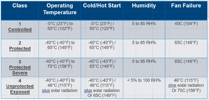 Figure 1. GR-3108-CORE Equipment ClassesThe four Classes of equipment defined in GR-3108-CORE are:
Class 1: Equipment in Controlled or Protected Environments
Class 2: Protected Equipment in Outside Environments
Class 3: Protected Equipment in Severe Outside Environments
Class 4: Products in Unprotected Environment directly exposed to the weather
The primary drivers of these classes include:
- Thermal, including Cold Start and Hot Start
- Temperature and Humidity Cycling
- Salt Fog Exposure
- Closure and Housing Requirements
Class 1: Equipment in Controlled or Protected Environments
The OSP for Class 1 enclosures includes Controlled Environmental Vaults, Huts and Cabinets with active heating and cooling, Telecom Closets in-Building/on-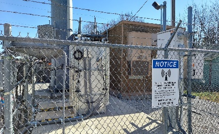 Figure 2. Typical OSP Enclosure and Concrete HutBuilding or Residential Locations. The requirements for Class 1 installations are very much in line with NEBS Level 3 specifications with the recurring theme on these enclosures being that there is some active means of environmental control. The methods of maintaining a controlled environment are not specified, but the method used must maintain the defined operating temperatures between -5°C (23°F) to 50°C (122°F) and humidity levels between 5-85 percent.
Other expectations for Class 1 enclosures include performing initial, cold, or hot startup throughout the entire temperature range and continued operation if device single fan failures occurs, but at a lower upper-temperature threshold.
Class 2: Protected Equipment in Outside Environments
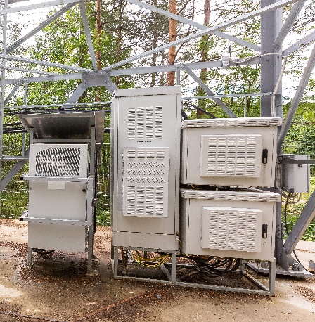 Figure 3. Example Class 2 Protected EnclosuresThe internal enclosures or spaces of a Class 2 OSP have an extended temperature range of -40°C (-40°F) to 65°C (149°F), with humidity levels the same as for Class 1. Typically, while these OSPs continue to protect the hardware from the outside elements, environmental controls are less capable and often involve the use of cooling fans, heat exchangers and raised fins to dissipate heat. Besides outdoor enclosures, Class 2 environments can also include customer premise locations such as garages, attics or uncontrolled warehouses.
For hardware designers, creating Carrier Grade Servers, this is where it’s particularly important to pay attention to the components being used when you’re looking at your target Class 2 deployment environment. Many manufacturers will provide specifications on the maximum temperature where the IC component will operate. Typically, the maximum temperature is a die temperature, and the method of heat evacuation is left to the HW designers, in the form of heat sinks, fans for airflow, and others.
However, for those attempting compliance with Class 2, the lower temperature range also becomes important because many ICs are not tested for operation below 0°C. The IC temperature grades generally come in commercial (0°C/32°F to 70°C/158°F), Industrial (-40°C/-40°F to 85°C/185°F), Military (-55°C/-67°F to 125°C/257°F), and Automotive grades.
So the specs for Commercial grade ICs may not even accommodate the requirements of even a Class 1 OSP. So, what do designers do? Sometimes, you’ll see an “asterisk” on the server spec sheet, indicating that the device can run at the lower temperature range, but not start at the lower range. This is where the design can start at 0C and provide sufficient heat to keep the IC warm down through -5°C (23°F).
Designers may also consider including some pre-heater or enclosure heater to bring the device up to 0°C before a startup is allowed or incur the added expense of extended temperature parts.
Class 3: Protected Equipment in Severe Outside Environments
Severe is certainly the theme for Class 3 OSPs. In these environments, while inside an enclosure to protect the device from direct sunlight and rain, the enclosure may not be sealed from other outside stresses like hot, cold and humidity extremes, dust and other airborne contaminants, salt fog, etc. Temperature ranges from -40°C (-40°F) to 70°C (158°F) and humidity levels from 5% to 95%, with single fan failure requirements of 65°C. Certainly, indoor hostile environments, such as boiler rooms, furnace spaces and attics also exist that would require Class 3 designed solutions.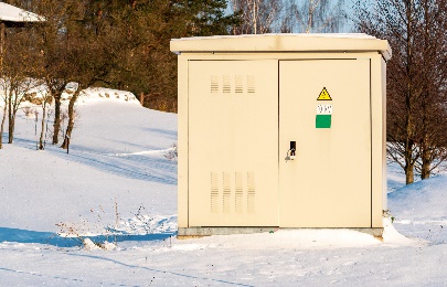 Figure 4.Protected Sever Cabinet
Class 4: Products in Unprotected Environment directly exposed to the weather
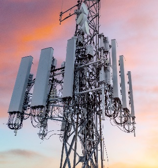 Figure 5. Class 4 Radio UnitsThis class of equipment is intended for outdoor deployments, with full exposure to sun, rain, wind and all the environmental challenges found, for example, at the top of a Cell Tower. For Telecom, Class 4 certification would typically be the domain of Antennas and Remote Radio Heads. These units, mounted on towers, buildings, street lamps, and other places are fully exposed to the entire spectrum of environmental challenges. Class 4 devices get a bit of a break on temperature, -40°C (-40°F) to 46°C (115°F), due to direct exposure to sunlight, but 100% humidity due to its exposure to rain.
Conclusion
For Carrier Grade Servers, Class 1 (NEBS Level 3 equivalent) is the most common target of designers creating compute, storage, and networking platforms for Telecom consumption. Class 2 servers are also achievable, and their demand may increase as Edge Computing and O-RAN/Cloud RAN deployments become more common, moving beyond Class 2 will require specialty, more purpose-defined designs.
Related Blog Posts

Dell Shifts vRAN into High Gear on PowerEdge with Intel vRAN Boost
Thu, 17 Aug 2023 18:33:05 -0000
|Read Time: 0 minutes
What has past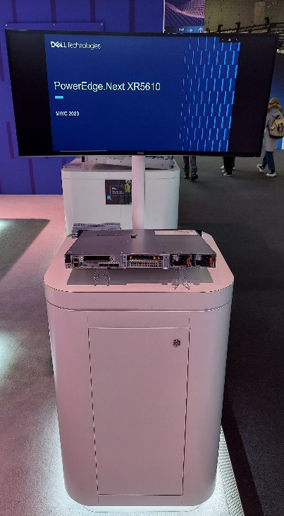
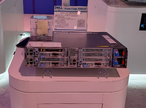
Mobile World Congress 2023 was an important event for both Dell Technologies and Intel that marked a true foundational turning point for vRAN viability. At this event, Intel launched its 4th Gen Intel Xeon Scalable processor, with Intel vRAN Boost, and Dell announced two new ruggedized server platforms, the PowerEdge XR5610 and XR8000, with support for vRAN Boost CPU SKUs.
The features and capabilities of the PowerEdge XR5610 and XR8000 have been highlighted in previous blogs and both have been available to order since May 2023. These new ruggedized servers have been evaluated and adopted as Cloud RAN reference platforms by NEPs such as Samsung and Ericsson. Short-depth, NEBS certified and TCO-optimized, these servers are purpose-built for the demanding deployment environments of Mobile Operators and are now married to the Intel vRAN Boost processor to provide a powerful and efficient alternative to classical appliance options.
What is now
Starting August 16, 2023, the 4th Gen Intel Xeon Scalable processor with Intel vRAN Boost is available to order with the PowerEdge XR5610 and XR8000. These two critical pieces of the vRAN puzzle have been brought together and are now available to order from our PowerEdge XR Rugged Servers page with the following CPU SKUs.
| CPU SKU | Cores | Base Freq. | TDP |
|---|---|---|---|
6433 N | 32 | 2.0 | 205 W |
5423 N | 20 | 2.1 | 145 W |
6423 N | 28 | 2.0 | 195 W |
6403 N | 24 | 1.9 | 185 W |
Table 1. Intel vRAN Boost SKUs available today from Dell
Additional details on these new CPU SKUs and all 4th Gen Intel® Xeon® Scalable processors can be found on the Intel Ark Site.
These processors, with Intel vRAN Boost, integrate key acceleration blocks for 4G and 5G Radio Layer 1 processing into the CPU. These include:
- 5G Low Density Parity Check (LDPC) encoder/decoder
- 4G Turbo encoder/decoder
- Rate match/dematch
- Hybrid Automatic Repeat
- Request (HARQ) with access to DDR memory for buffer management
- Fast Fourier Transform (FFT) block providing DFT/iDFT for the 5G Sounding Reference Signal (SRS)
- Queue Manager (QMGR)
- DMA subsystem
One of the most interesting features of the vRAN Boost CPU is how this acceleration block is accessed by software. Although it is integrated on-chip with the CPU, the vRAN Boost block still presents itself to the Cores/OS as a PCIe device. The genius of this approach is in software compatibility. Virtual Distributed Unit (vDU) applications written for the previous generation HW will access the new vRAN Boost block using the same standardized, open APIs that were developed for the previous generation product. This creates a platform that can support past, present (and possibly future) generations of Intel’s vRAN optimized HW with the same software image.
What is to come
Prior to vRAN Boost, the reference architecture for vDU was a 3rd Gen Intel Xeon Scalable processor along with a FEC/LDPC accelerator, such as the Intel vRAN Accelerator ACC100 Adapter, and most today’s vRAN deployments can be found with this configuration. While the ACC100 does meet the L1 acceleration needs of vRAN it does this at a price, in terms of the space of an HHHL PCIe card and at the cost of an additional 54 W of power consumed (and cooled). In addition, using a PCIe interface will further reduce additional I/O expansion options and impact the ability to scale in-chassis due to slot count – both of which are alleviated with vRAN Boost.
With the new Intel vRAN Boost processors’ fully integrated acceleration, Intel has taken a huge step in closing the performance gap with purpose-built hardware, while remaining true to the “Open” in O-RAN.
Intel says that, compared to the previous generation, the new Intel vRAN Boost processor delivers up to 2x capacity and ~ 20% compute power savings compared to its previous generation processor with ACC100 external acceleration. At the Cell Site, where every watt is counted, operators are constantly exploring opportunities to reduce both power consumption and the associated “cooling tax” of keeping the HW in its operational range, typically within a sealed environment.
Dell and Intel have worked together to provide early access Intel vRAN Boost provisioned XR5610s and XR8000s to multiple partners and customers for integration, evaluation, and proof-of-concepts. One early evaluator, Deutsche Telekom, states:
“Deutsche Telekom recently conducted a performance evaluation of Dell’s PowerEdge XR5610 server, based on Intel’s 4th Gen Intel Xeon Scalable processor with Intel vRAN Boost. Testing under selected scenarios concluded a 2x capacity gain, using approximately 20% less power versus the previous generation. We aim to leverage these significant performance gains on our journey to vRAN.”
-- Petr Ledl , Vice President of Network Trials and Integration Lab and Access Disaggregation Chief Architect, Deutsche Telekom AG
With such a solid industry foundation of the telecom-optimized PowerEdge XR5610s/XR8000s, and 4th Gen Intel Xeon Scalable processors with Intel vRAN Boost, expect to see accelerated deployments of open, vRAN-based infrastructure solutions.
Dell’s PowerEdge XR4000 for Telecom/Edge Compute
Wed, 08 Feb 2023 18:04:19 -0000
|Read Time: 0 minutes
Compute capabilities are increasingly migrating away from the centralized data center and deployed closer to the end user—where data is created, processed, and analyzed in order to generate rapids insights and new value.
Dell Technologies is committed to building infrastructure that can withstand unpredictable and challenging deployment environments. In October 2022, Dell announced the PowerEdge XR4000, a high-performance server, based on the Intel® Xeon® D Processor that is designed and optimized for edge use cases.
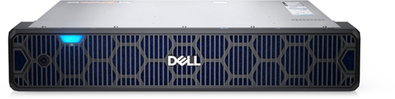
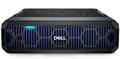
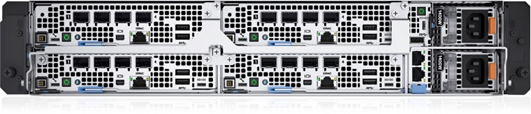
Figure 1. Dell PowerEdge XR4000 “rackable” (left) and “stackable” (right) Edge Optimized Servers
The PowerEdge XR4000 is designed from the ground up with the specifications to withstand rugged and harsh deployment environments for multiple industry verticals. This includes a server/chassis designed with the foundation requirements of GR-63-CORE (including -5C to +55C operations) and GR1089-CORE for NEBS Level 3 and GR-3108 Class 1 certification. Designed beyond the NEBS requirements of Telecom, the XR4000 also meets MIL-STD specifications for defense applications, marine specifications for shipboard deployments, and environmental requirements for installations in the power industry.
The XR4000 marks a continuation of Dell Technologies’ commitment to creating platforms that can withstand the unpredictable and often challenging deployment environments encountered at the edge, as focused compute capabilities are increasingly migrating away from the Centralized Data Center and deployed closer to the End User, at the Network Edge or OnPrem.
Attention to a wide range of deployment environments creates a platform that can be reliably deployed from the Data Center to the Cell Site, to the Desktop, and anywhere in between. Its rugged design makes the XR4000 an attractive option to deploy at the Industrial Edge, on the Manufacturing Floor, with the power and expandability to support a wide range of computing requirements, including AI/Analytics with bleeding-edge GPU-based acceleration.
The XR4000 is also an extremely short depth platform, measuring only 342.5mm (13.48 inches) in depth which makes it extremely deployable into a variety of locations. And with a focus on deployments, the XR4000 supports not only EIA-310 compatible 19” rack mounting rails, but also the “stackable” version supports common, industry-standard VESA/DIN rail mounts, with built-in latches to allow the chassis to be mounted on top of each other, leveraging a single VESA/DIN mount.
Additionally, both Chassis types have the option to include a lockable intelligent filtered bezel, to prevent unwanted access to the Sleds and PSUs, with filter monitoring which will create a system alert when the filter needs to be changed. Blocking airborne contaminants, as discussed in a previous blog, is key to extending the life of a server by reducing contaminant build-up that can lead to reduced cooling performance, greater energy costs, corrosion and outage-inducing shorts.
The modular design of the XR4000, along with the short-depth Compute Sled design creates an easily scalable solution. Maintenance procedures are simplified with an all-front-facing, sled-based design.
Conclusion
Specifying and deploying Edge Compute can very often involve selecting a Server Solution outside of the more traditional data center choices. The XR4000 addresses the challenges of moving to compute to the Edge with a compact, NEBS-compliant, and ruggedized approach, with Sled-based servers and all front access, reversible airflow and flexible mounting options, to provide ease of maintenance and upgrades, reducing server downtime and improving TCO.