
Layer 3 topology configurations
Layer 3 topology configurations
-
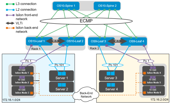
Figure 17. Layer 3 topology
Note: The configuration files for every switch in this topology are provided in the Configuration Files section at the end of this document.
Configuration of Z9100-ON OS10EE spine switches
The configuration of the example used in this guide begins with the two Z9100-ONs Spine1 and Spine2, as seen in the following figure:
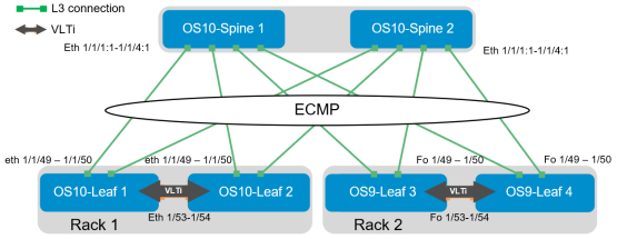
Figure 18. OS10EE spine
Set the hostname, then configure the OOB management interface and default gateway.
Z9100-ON Spine 1
Z9100-ON Spine 2
configure terminal
hostname Z9100-Spine1
interface mgmt 1/1/1
no ip address dhcp
no shutdown
ip address 100.67.169.37/24
management route 0.0.0.0/0 100.67.169.254
configure terminal
hostname Z9100-Spine2
interface mgmt 1/1/1
no ip address dhcp
no shutdown
ip address 100.67.169.36/24
management route 0.0.0.0/0 100.67.169.254
Configure the four point-to-point interfaces connected to leaf switches. In this example, each of the connections from the Z9100-ON spine to the S4048-ON leaf switches must have the speed set to 40 GbE. Next, assign IP addresses per Table 3. Configure a loopback interface to be used as the router ID. Isilon’s OneFS supports and recommends the use of jumbo frames. Each interface used below is configured using jumbo frames.
Z9100-ON Spine 1
Z9100-ON Spine 2
interface breakout 1/1/1 map 40g-1x
interface breakout 1/1/2 map 40g-1x
interface breakout 1/1/3 map 40g-1x
interface breakout 1/1/4 map 40g-1x
interface ethernet1/1/1:1
description “S4048-Leaf1”
no shutdown
no switchport
mtu 9216
ip address 192.168.1.0/31
interface ethernet1/1/2:1
description “S4048-Leaf2”
no shutdown
no switchport
mtu 9216
ip address 192.168.1.2/31
interface ethernet1/1/3:1
description “S4048-Leaf3”
no shutdown
no switchport
mtu 9216
ip address 192.168.1.4/31
interface ethernet1/1/4:1
description “S4048-Leaf4”
no shutdown
no switchport
mtu 9216
ip address 192.168.1.6/31
interface loopback0
description “Router ID”
no shutdown
ip address 10.0.1.1/32
interface breakout 1/1/1 map 40g-1x
interface breakout 1/1/2 map 40g-1x
interface breakout 1/1/3 map 40g-1x
interface breakout 1/1/4 map 40g-1x
interface ethernet1/1/1:1
description “S4048-Leaf1”
no shutdown
no switchport
mtu 9216
ip address 192.168.2.0/31
interface ethernet1/1/2:1
description “S4048-Leaf2”
no shutdown
no switchport
mtu 9216
ip address 192.168.2.2/31
interface ethernet1/1/3:1
description “S4048-Leaf3”
no shutdown
no switchport
mtu 9216
ip address 192.168.2.4/31
interface ethernet1/1/4:1
description “S4048-Leaf4”
no shutdown
no switchport
mtu 9216
ip address 192.168.2.6/31
interface loopback0
description “Router ID”
no shutdown
ip address 10.0.1.2/32
Configure a route map and IP prefix list to redistribute all loopback addresses and leaf networks via BGP.
The command seq 10 permit 10.0.1.0/24 ge 32 includes all addresses in the 10.0.1.0/24 address range with a mask greater than or equal to 32. This includes all loopback addresses used as router IDs.
Z9100-ON Spine 1
Z9100-ON Spine 2
route-map spine-leaf permit 10
match ip address prefix-list spine-leaf
ip prefix-list spine-leaf seq 10 permit 10.0.1.0/24 ge 32
route-map spine-leaf permit 10
match ip address prefix-list spine-leaf
ip prefix-list spine-leaf seq 10 permit 10.0.1.0/24 ge 32
Use these commands to configure BGP.
First, enable eBGP with the router bgp ASN command. The ASN is from Figure 14.
The bgp bestpath as-path multipath-relax command enables ECMP. The maximum-paths ebgp 2 command specifies the maximum number of parallel paths to a destination to add to the routing table. In this topology, there are two equal cost best paths from a spine to a host, one to each leaf to which the host is connected.
BGP neighbors are configured, and Neighbor fall-over is enabled. Graceful restart enables the data plane to continue forwarding traffic for a time if the BGP process fails or quits.
BGP hello and hold down timers are set to three and nine seconds, respectively. Neighbor fall-over triggers route withdrawal when IP connectivity between BGP peers is lost. The more aggressive timers (default is 60 seconds hello and 180 seconds hold down) are for backup. The advertisement interval is set to one second. This is to prevent BGP speakers from advertising updates immediately upon receipt. Instead, they advertise them in batched intervals of one second. This delay is to prevent overhead.
Finally, exit configuration mode and save the configuration.
Z9100-ON Spine 1
Z9100-ON Spine 2
router bgp 64601
bestpath as-path multipath-relax
graceful-restart role receiver-only
maximum-paths ebgp 2
address-family ipv4 unicast
redistribute connected route-map spine-leaf
template spine-leaf
advertisement-interval 1
fall-over
timers 3 9
neighbor 192.168.1.1
inherit template spine-leaf
remote-as 64701
no shutdown
neighbor 192.168.1.3
inherit template spine-leaf
remote-as 64702
no shutdown
neighbor 192.168.1.5
inherit template spine-leaf
remote-as 64703
no shutdown
neighbor 192.168.1.7
inherit template spine-leaf
remote-as 64704
no shutdown
end
write memory
router bgp 64602
bestpath as-path multipath-relax
graceful-restart role receiver-only
maximum-paths ebgp 2
address-family ipv4 unicast
redistribute connected route-map spine-leaf
template spine-leaf
advertisement-interval 1
fall-over
timers 3 9
neighbor 192.168.2.1
inherit template spine-leaf
remote-as 64701
no shutdown
neighbor 192.168.2.3
inherit template spine-leaf
remote-as 64702
no shutdown
neighbor 192.168.2.5
inherit template spine-leaf
remote-as 64703
no shutdown
neighbor 192.168.2.7
inherit template spine-leaf
remote-as 64704
no shutdown
end
write memory
Configuration of S4048-ON OS10EE leaf switches
Configurations of the leaf switches one and two running OS10EE are shown in the following figure:
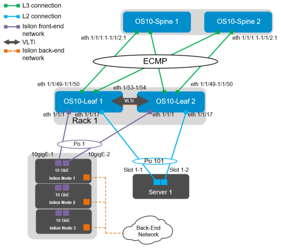
Figure 19. OS10EE leaf pair
The interfaces for additional Isilon nodes and servers in this example can be found in the following table:
Table 4. Interface enumeration
Server/Isilon node
Switch
Leaf interface
Node 01-1
Leaf 1
ethernet 1/1/1
Leaf 2
ethernet 1/1/1
Node 01-2
Leaf 1
ethernet 1/1/3
Leaf 2
ethernet 1/1/3
Node 01-3
Leaf 1
ethernet 1/1/5
Leaf 2
ethernet 1/1/5
Server 01
Leaf 1
ethernet 1/1/17
Leaf 2
ethernet 1/1/17
Server 02
Leaf 1
ethernet 1/1/19
Leaf 2
ethernet 1/1/19
First, set the hostname, then configure the OOB management interface and default gateway. Enable RSTP as a precaution against creating a networking loop. S4048-Leaf 1 is configured as the primary RSTP root bridge using the bridge-priority 0 command. S4048-Leaf 2 is configured as the secondary RSTP root bridge using the bridge-priority 4096 command. This ensures that leaf 1 is always the root bridge. The no iscsi enable command is issued to ensure that iSCSI snooping is disabled.
S4048-ON Leaf 1
S4048-ON Leaf 2
configure terminal
hostname S4048-Leaf1
interface mgmt 1/1/1
no ip address dhcp
ip address 100.67.170.15/24
management route 0.0.0.0/0 100.67.170.254
no iscsi enable
spanning-tree mode rstp
spanning-tree rstp priority 0
configure terminal
hostname S4048-Leaf2
interface mgmt 1/1/1
no ip address dhcp
ip address 100.67.170.14/24
management route 0.0.0.0/0 100.67.171.254
no iscsi enable
spanning-tree mode rstp
spanning-tree rstp priority 4096
Configure the VLT interconnect between S4048-Leaf1 and S4048-Leaf2. In this configuration, remove each interface from Layer 2 mode with the no switchport command for interfaces eth 1/1/53–1/1/54. Once this is done, create the VLT domain, add the backup destination, and add the interfaces participating in VLTi. Finally, enable VLT peer routing on each switch. Once VLT is enabled, it dynamically changes the MTU settings for the VLTi to a value of 9216. Isilon’s OneFS supports and recommends the use of jumbo frames.
Note: Refer to Dell EMC Isilon: Network Design Considerations for more information about specific protocols as they relate to OneFS.
S4048-ON Leaf 1
S4048-ON Leaf 2
interface range ethernet 1/1/53-1/1/54
description VLTi
no switchport
vlt-domain 127
backup destination 100.67.170.14
discovery-interface ethernet 1/1/53, 1/1/54
interface range ethernet 1/1/53-1/1/54
description VLTi
no switchport
vlt-domain 127
backup destination 100.67.170.15
discovery-interface ethernet 1/1/53, 1/1/54
Next, the VLANs are configured. There is one VLAN for each Isilon subnet; this also includes the servers in each rack. Virtual Router Redundancy Protocol (VRRP) is used as a secondary from of redundancy. Although VRRP is an active/standby First Hop Redundancy Protocol (FHRP), when combined with VLT it becomes active/active. The priority is assigned to give predictability of VRRP master. The higher priority is elected as the master. If no priority is given, the higher IP address is elected as the master.
S4048-ON Leaf 1
S4048-ON Leaf 2
interface vlan 100
ip address 172.16.1.252/24
no shutdown
mtu 9216
vrrp-group 100
priority 150
virtual-address 172.16.1.254
interface vlan 100
ip address 172.16.1.253/24
no shutdown
mtu 9216
vrrp-group 100
priority 100
virtual-address 172.16.1.254
Note: Further information about all protocols that are used in this document and their use cases can be found in the Leaf-Spine Deployment and Best Practices Guide and Dell EMC Networking Layer 3 Leaf-Spine Deployment and Best Practices with OS10.
Configure the necessary port channels. There is one port channel for each server as well as a single port channel for each of the Isilon nodes. Each port channel is assigned an MTU of 9216 to support jumbo frames, and each is configured to allow access to VLAN 100. The vlt-port-channel command enables port channels on VLT peers to function as a single port channel.
S4048-ON Leaf 1
S4048-ON Leaf 2
interface port-channel1
description “Isilon Node 1”
no shutdown
switchport access vlan 100
mtu 9216
vlt-port-channel 1
spanning-tree port type edge
interface port-channel3
description “Isilon Node 2”
no shutdown
switchport access vlan 100
mtu 9216
vlt-port-channel 3
spanning-tree port type edge
interface port-channel5
description “Isilon Node 3”
no shutdown
switchport access vlan 100
mtu 9216
vlt-port-channel 5
spanning-tree port type edge
interface port-channel101
description “Server 1”
no shutdown
switchport access vlan 100
mtu 9216
vlt-port-channel 101
spanning-tree port type edge
interface port-channel102
description “Server 2”
no shutdown
switchport access vlan 100
mtu 9216
vlt-port-channel 102
spanning-tree port type edge
The downstream interfaces are configured in the next section. Dell recommends asymmetrical flow control (rx on tx off) on S4048-ON leaf switches which have sufficient egress buffers to reduce packet drops and resulting retransmissions. This feature is applied to all host interfaces that support flow control. In OS10EE, this is enabled by default; while in OS9, it must be configured. Flow control commands are added below for reference; however, they are not required in OS10EE.
S4048-ON Leaf 1
S4048-ON Leaf 2
interface ethernet1/1/1
description “Isilon Node 1-10gige-1”
no shutdown
channel-group 1 mode active
no switchport
mtu 9216
flowcontrol receive on
flowcontrol transmit off
interface ethernet1/1/3
description “Isilon Node 2-10gige-1”
no shutdown
channel-group 3 mode active
no switchport
mtu 9216
flowcontrol receive on
flowcontrol transmit off
interface ethernet1/1/5
description “Isilon Node 3-10gige-1”
no shutdown
channel-group 5 mode active
no switchport
mtu 9216
flowcontrol receive on
flowcontrol transmit off
interface ethernet1/1/17
description “Server 1-1”
no shutdown
channel-group 101 mode active
no switchport
mtu 9216
flowcontrol receive on
flowcontrol transmit off
interface ethernet1/1/19
description “Server 2-1”
no shutdown
channel-group 102 mode active
no switchport
mtu 9216
flowcontrol receive on
flowcontrol transmit off
interface ethernet1/1/1
description “Isilon Node 1-10gige-2”
no shutdown
channel-group 1 mode active
no switchport
mtu 9216
flowcontrol receive on
flowcontrol transmit off
interface ethernet1/1/3
description “Isilon Node 2-10gige-2”
no shutdown
channel-group 3 mode active
no switchport
mtu 9216
flowcontrol receive on
flowcontrol transmit off
interface ethernet1/1/5
description “Isilon Node 3-10gige-2”
no shutdown
channel-group 5 mode active
no switchport
mtu 9216
flowcontrol receive on
flowcontrol transmit off
interface ethernet1/1/17
description “Server 1-2”
no shutdown
channel-group 101 mode active
no switchport
mtu 9216
flowcontrol receive on
flowcontrol transmit off
interface ethernet1/1/19
description “Server 2-2”
no shutdown
channel-group 102 mode active
no switchport
mtu 9216
flowcontrol receive on
flowcontrol transmit off
The two upstream Layer 3 interfaces connected to the spine switches are configured. Assign IP addresses per Table 3. Configure a loopback interface to be used as the router ID. This is used with BGP.
S4048-ON Leaf 1
S4048-ON Leaf 2
interface ethernet1/1/49
description “Spine 1”
no shutdown
no switchport
mtu 9216
ip address 192.168.1.1/31
interface ethernet1/1/50
description “Spine 2”
no shutdown
no switchport
mtu 9216
ip address 192.168.2.1/31
interface loopback0
description “Router ID”
no shutdown
ip address 10.0.2.1/32
interface ethernet1/1/49
description “Spine 1”
no shutdown
no switchport
mtu 9216
ip address 192.168.1.3/31
interface ethernet1/1/50
description “Spine 2”
no shutdown
no switchport
mtu 9216
ip address 192.168.2.3/31
interface loopback0
description “Router ID”
no shutdown
ip address 10.0.2.2/32
Configure a route map and IP prefix list to redistribute all loopback addresses and leaf networks through BGP.
The command ip prefix-list spine-leaf seq 10 permit 10.0.2.0/24 ge 32 includes all addresses in the 10.0.2.0/24 address range with a mask greater than or equal to 32. This includes all loopback addresses used as router IDs.
The command ip prefix-list spine-leaf seq 20 permit 172.16.0.0/16 ge 24 includes the 172.16.2.0/24 network used on Leaf switches 3 and 4, as shown in Figure 17.
S4048-ON Leaf 1
S4048-ON Leaf 2
route-map spine-leaf permit 10
match ip address prefix-list spine-leaf
ip prefix-list spine-leaf seq 10 permit 10.0.2.0/24 ge 32
ip prefix-list spine-leaf seq 20 permit 172.16.0.0/16 ge 24
route-map spine-leaf permit 10
match ip address prefix-list spine-leaf
ip prefix-list spine-leaf seq 10 permit 10.0.2.0/24 ge 32
ip prefix-list spine-leaf seq 20 permit 172.16.0.0/16 ge 24
Uplink Failure Detection (UFD) is configured next. UFD is a feature that shuts down specified downstream interfaces when all specified uplinks become disabled.
S4048-ON Leaf 1
S4048-ON Leaf 2
uplink-state-group 1
enable
downstream port-channel1
downstream port-channel3
downstream port-channel5
downstream port-channel101
downstream port-channel102
upstream ethernet1/1/49
upstream ethernet1/1/50
uplink-state-group 1
enable
downstream port-channel1
downstream port-channel3
downstream port-channel5
downstream port-channel101
downstream port-channel102
upstream ethernet1/1/49
upstream ethernet1/1/50
Use these commands to configure eBGP.
First, enable eBGP with the router bgp ASN command. The ASN is from Figure 14.
The bgp bestpath as-path multipath-relax enables ECMP. The maximum-paths ebgp 2 command specifies the maximum number of parallel paths to a destination to add to the routing table. In this topology, there are two equal cost best paths from a spine to a host, one to each leaf that to which the host is connected.
BGP neighbors are configured, and neighbor fall-over is enabled. Graceful restart enables the data plane to continue forwarding traffic for a time if the BGP process fails or quits.
BGP hello and hold down timers are set to three and nine seconds, respectively. Neighbor fall-over triggers route withdrawal when IP connectivity between BGP peers is lost. The more aggressive timers (default is 60 seconds hello and 180 seconds hold down) are for backup. The advertisement interval is set to one second. This is to prevent BGP speakers from advertising updates immediately upon receipt. Instead, they advertise them in batched intervals of one second. This delay is to prevent overhead.
Finally, exit configuration mode and save the configuration.
S4048-ON Leaf 1
S4048-ON Leaf 2
router bgp 64701
bestpath as-path multipath-relax
graceful-restart role receiver-only
maximum-paths ebgp 2
address-family ipv4 unicast
redistribute connected route-map spine-leaf
template spine-leaf
advertisement-interval 1
fall-over
timers 3 9
neighbor 192.168.1.0
inherit template spine-leaf
remote-as 64601
no shutdown
neighbor 192.168.2.0
inherit template spine-leaf
remote-as 64602
no shutdown
end
write memory
router bgp 64702
bestpath as-path multipath-relax
graceful-restart role receiver-only
maximum-paths ebgp 2
address-family ipv4 unicast
redistribute connected route-map spine-leaf
template spine-leaf
advertisement-interval 1
fall-over
timers 3 9
neighbor 192.168.1.2
inherit template spine-leaf
remote-as 64601
no shutdown
neighbor 192.168.2.2
inherit template spine-leaf
remote-as 64602
no shutdown
end
write memory
Configuration of S4048-ON OS9 leaf switches
Configurations in this section cover leaf switches 3 and 4 running OS9, as seen in the following figure:
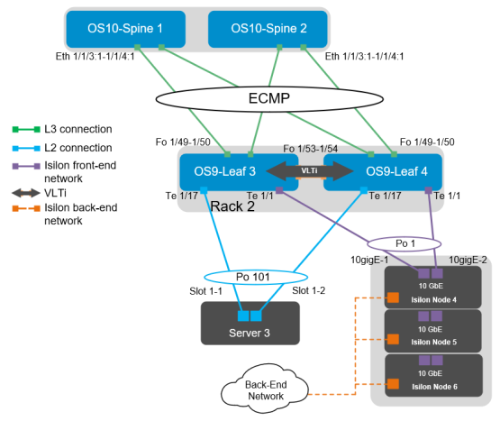
Figure 20. OS9 leaf pair
The ports for additional Isilon nodes and servers in this example can be found in the following table:
Table 5. Interface enumeration
Server/Isilon node
Switch
Leaf interface
Node 01-4
Leaf 3
tengigabitethernet 1/1/1
Leaf 4
tengigabitethernet 1/1/1
Node 01-5
Leaf 3
tengigabitethernet 1/1/3
Leaf 4
tengigabitethernet 1/1/3
Node 01-6
Leaf 3
tengigabitethernet 1/1/5
Leaf 4
tengigabitethernet 1/1/5
Server 03
Leaf 3
tengigabitethernet 1/1/17
Leaf 4
tengigabitethernet 1/1/17
Server 04
Leaf 3
tengigabitethernet 1/1/19
Leaf 4
tengigabitethernet 1/1/19
First, set the hostname and configure the OOB management interface and default gateway. Next, enable LLDP as well as RSTP. In OS10EE, LLDP is enabled by default, while in OS9 it must be enabled. S4048-Leaf 3 is configured as the primary RSTP root bridge using the bridge-priority 0 command. S4048-Leaf 4 is configured as the secondary RSTP root bridge using the bridge-priority 4096 command. This ensures that leaf 3 is always the root bridge.
S4048-ON Leaf 3
S4048-ON Leaf 4
configure terminal
hostname S4048-Leaf3
interface management 1/1
ip address 100.67.171.15/24
no shutdown
management route 0.0.0.0/0 100.67.171.254
protocol lldp
advertise management-tlv management- address system-description system-name
advertise interface-port-desc
protocol spanning-tree rstp
bridge-priority 0
no disable
configure terminal
hostname S4048-Leaf4
interface management 1/1
ip address 100.67.171.14/24
no shutdown
management route 0.0.0.0/0 100.67.171.254
protocol lldp
advertise management-tlv management-address system-description system-name
advertise interface-port-desc
protocol spanning-tree rstp
bridge-priority 4096
no disable
Configure the VLT interconnect between S4048-Leaf3 and S4048-Leaf4. Create a static port channel and add the two VLTi connections to port channel 128. Configure the VLT domain using the IP address assigned to the management interface of the opposing switch as the backup destination. The backup destination is only utilized for the VLT heartbeat. Once VLT is enabled, it dynamically changes the MTU settings for the VLTi to a value of 9216.
S4048-ON Leaf 3
S4048-ON Leaf 4
interface port-channel128
description VLTi
channel-member fortyGigE 1/53
channel-member fortyGigE 1/54
no shutdown
no switchport
interface fortyGigE 1/53
description VLTi
no shutdown
no switchport
interface fortyGigE 1/54
description VLTi
no shutdown
no switchport
vlt domain 127
peer-link port-channel 128
back-up destination 100.67.171.14
unit-id 0
peer-routing
interface port-channel128
description VLTi
channel-member fortyGigE 1/53
channel-member fortyGigE 1/54
no shutdown
no switchport
interface fortyGigE 1/53
description VLTi
no shutdown
no switchport
interface fortyGigE 1/54
description VLTi
no shutdown
no switchport
vlt domain 127
peer-link port-channel 128
back-up destination 100.67.171.15
unit-id 1
peer-routing
The downstream interfaces are configured in the next section. Dell recommends asymmetrical flow control (rx on tx off) on S4048-ON leaf switches that have sufficient egress buffers to reduce packet drops and resulting retransmissions. This feature is applied on all host interfaces that support flow control. In OS10EE, this is enabled by default, while in OS9 it must be configured. Flow control is configured with the flowcontrol rx on tx off command.
S4048-ON Leaf 3
S4048-ON Leaf 4
interface tengigabitethernet 1/1
description “Isilon Node 4-10gige-1”
no shutdown
port-channel-protocol LACP
port-channel 1 mode active
mtu 9216
flowcontrol rx on tx off
interface tengigabitethernet 1/3
description “Isilon Node 5-10gige-1”
no shutdown
port-channel-protocol LACP
port-channel 3 mode active
mtu 9216
flowcontrol rx on tx off
interface tengigabitethernet 1/5
description “Isilon Node 6-10gige-1”
no shutdown
port-channel-protocol LACP
port-channel 5 mode active
mtu 9216
flowcontrol rx on tx off
interface tengigabitethernet 1/17
description “Server 3-1”
no shutdown
port-channel-protocol LACP
port-channel 101 mode active
mtu 9216
flowcontrol rx on tx off
interface tengigabitethernet 1/19
description “Server 4-1”
no shutdown
port-channel-protocol LACP
port-channel 102 mode active
mtu 9216
flowcontrol rx on tx off
interface tengigabitethernet 1/1
description “Isilon Node 4-10gige-2”
no shutdown
port-channel-protocol LACP
port-channel 1 mode active
mtu 9216
flowcontrol rx on tx off
interface tengigabitethernet 1/3
description “Isilon Node 5-10gige-2”
no shutdown
port-channel-protocol LACP
port-channel 3 mode active
mtu 9216
flowcontrol rx on tx off
interface tengigabitethernet 1/5
description “Isilon Node 6-10gige-2”
no shutdown
port-channel-protocol LACP
port-channel 5 mode active
mtu 9216
flowcontrol rx on tx off
interface tengigabitethernet 1/17
description “Server 3-2”
no shutdown
port-channel-protocol LACP
port-channel 101 mode active
mtu 9216
flowcontrol rx on tx off
interface tengigabitethernet 1/19
description “Server 4-2”
no shutdown
port-channel-protocol LACP
port-channel 102 mode active
mtu 9216
flowcontrol rx on tx off
If the S4048-ON running OS9 is used for the first leaf pair, the interfaces for the first Isilon node must be left out of the port channel to facilitate the configuration of the LACP connections in OneFS. In this example, this is tengigabitethernet 1/1 on both switches. The configuration is as follows for this example:
interface tengigabitethernet 1/1
description “Isilon Node 4-10gige-1”
switchport
no shutdown
mtu 9216
interface vlan200
no shutdown
mtu 9216
ip address 172.16.2.252/24
untagged port-channel 3,5,101,102
untagged interface te 1/1
Configure the necessary port channels. There is one port channel for each server, as well as a single port channel for each of the Isilon nodes. Each port channel is assigned an MTU of 9216 to support jumbo frames. The vlt-port-channel # command enables port channels on VLT peers to function as a single port channel.
S4048-ON Leaf 3
S4048-ON Leaf 4
interface port-channel1
description “Isilon Node 4”
no shutdown
switchport
mtu 9216
vlt-peer-lag port-channel 1
spanning-tree rstp edge-port
interface port-channel3
description “Isilon Node 5”
no shutdown
switchport
mtu 9216
vlt-peer-lag port-channel 3
spanning-tree rstp edge-port
interface port-channel5
description “Isilon Node 6”
no shutdown
switchport
mtu 9216
vlt-peer-lag port-channel 5
spanning-tree rstp edge-port
interface port-channel101
description “Server 3”
no shutdown
switchport
mtu 9216
vlt-peer-lag port-channel 101
spanning-tree rstp edge-port
interface port-channel102
description “Server 4”
no shutdown
switchport
mtu 9216
vlt-peer-lag port-channel 102
spanning-tree rstp edge-port
Next, the VLANs are created. There is one VLAN for each Isilon subnet. This also includes the servers in each rack. Virtual Router Redundancy Protocol (VRRP) is used as a secondary form of redundancy. VRRP becomes active/active with the use of VLT over the standard active/passive. The priority is assigned to give predictability to the VRRP master.
Note: In this example, Server 3’s NIC is configured as an LACP NIC team. It is assigned the IP address 172.16.2.240/24. Server 3’s default gateway is configured as 172.16.2.254/24. The virtual address assigned to the VRRP group provides fault tolerance if either leaf goes offline.
S4048-ON Leaf 3
S4048-ON Leaf 4
interface vlan200
no shutdown
mtu 9216
ip address 172.16.2.252/24
untagged port-channel 1,3,5,101,102
vrrp-group 200
priority 150
virtual-address 172.16.2.254
interface vlan200
no shutdown
mtu 9216
ip address 172.16.2.253/24
untagged port-channel 1,3,5,101,102
vrrp-group 200
priority 100
virtual-address 172.16.2.254
The two upstream Layer 3 interfaces connected to the spine switches are configured. Assign IP addresses per Table 3. Configure a loopback interface to be used as the router ID. This is used with BGP.
S4048-ON Leaf 3
S4048-ON Leaf 4
interface fortyGigE 1/49
description “Spine 1”
no shutdown
no switchport
mtu 9216
ip address 192.168.1.5/31
interface fortyGigE 1/50
description “Spine 2”
no shutdown
no switchport
mtu 9216
ip address 192.168.2.5/31
interface loopback0
description “Router ID”
no shutdown
ip address 10.0.2.3/32
interface fortyGigE 1/49
description “Spine 1”
no shutdown
no switchport
mtu 9216
ip address 192.168.1.7/31
interface fortyGigE 1/50
description “Spine 2”
no shutdown
no switchport
mtu 9216
ip address 192.168.2.7/31
interface loopback0
description “Router ID”
no shutdown
ip address 10.0.2.4/32
Configure a route map and IP prefix-list to redistribute all loopback addresses and leaf networks through BGP.
The command seq 10 permit 10.0.2.0/24 ge 32 includes all addresses in the 10.0.2.0/24 address range with a mask greater than or equal to 32. This includes all loopback addresses used as router IDs.
The command seq 20 permit 172.16.0.0/16 ge 24 includes the 172.16.1.0/24 network used on Leafs 1 and 2, as shown in Figure 14.
S4048-ON Leaf 3
S4048-ON Leaf 4
route-map spine-leaf permit 10
match ip address spine-leaf
ip prefix-list spine-leaf
description Redistribute loopback and leaf networks
seq 10 permit 10.0.2.0/24 ge 32
seq 20 permit 172.16.0.0/16 ge 24
route-map spine-leaf permit 10
match ip address spine-leaf
ip prefix-list spine-leaf
description Redistribute loopback and leaf
networks
seq 10 permit 10.0.2.0/24 ge 32
seq 20 permit 172.16.0.0/16 ge 24
Include the point-to-point interfaces to each leaf pair in an ECMP group. Enable link bundle monitoring to report when traffic is unevenly distributed across multiple links.
Note: ECMP is not enabled until BGP or OSPF is configured.
S4048-ON Leaf 3
S4048-ON Leaf 4
ecmp-group 1
interface fortyGigE 1/49
interface fortyGigE 1/50
link-bundle-monitor enable
ecmp-group 1
interface fortyGigE 1/49
interface fortyGigE 1/50
link-bundle-monitor enable
Uplink Failure Detection (UFD) is configured next. UFD shuts down all downstream interfaces if all uplinks fail.
S4048-ON Leaf 3
S4048-ON Leaf 4
uplink-state-group 1
downstream port-channel1
downstream port-channel3
downstream port-channel5
downstream port-channel101
downstream port-channel102
upstream fortyGigE 1/49
upstream fortyGigE 1/50
uplink-state-group 1
downstream port-channel1
downstream port-channel3
downstream port-channel5
downstream port-channel101
downstream port-channel102
upstream fortyGigE 1/49
upstream fortyGigE 1/50
Use the following commands to configure BGP.
First, enable BGP with the router bgp ASN command. The ASN is from Figure 14.
The bgp bestpath as-path multipath-relax enables ECMP. The maximum-paths ebgp 2 command specifies the maximum number of parallel paths to a destination to add to the routing table. This number should be equal to or greater than the number of spines, up to 64.
BGP neighbors are configured, and fast fall-over is enabled.
Finally, exit configuration mode and save the configuration with the end and write commands.
S4048-ON Leaf 3
S4048-ON Leaf 4
router bgp 64703
bgp bestpath as-path multipath-relax
bgp graceful-restart
bgp graceful-restart role receiver-only
maximum-paths ebgp 2
redistribute connected route-map spine-leaf
neighbor spine-leaf peer-group
neighbor spine-leaf fall-over
neighbor spine-leaf timers 3 9
neighbor spine-leaf advertisement-interval 1
neighbor spine-leaf no shutdown
neighbor 192.168.1.4 remote-as 64601
neighbor 192.168.1.4 peer-group spine-leaf
neighbor 192.168.1.4 no shutdown
neighbor 192.168.2.4 remote-as 64602
neighbor 192.168.2.4 peer-group spine-leaf
neighbor 192.168.2.4 no shutdown
end
write memory
router bgp 64704
bgp bestpath as-path multipath-relax
bgp graceful-restart
bgp graceful-restart role receiver-only
maximum-paths ebgp 2
redistribute connected route-map spine-leaf
neighbor spine-leaf peer-group
neighbor spine-leaf fall-over
neighbor spine-leaf timers 3 9
neighbor spine-leaf advertisement-interval 1
neighbor spine-leaf no shutdown
neighbor 192.168.1.6 remote-as 64601
neighbor 192.168.1.6 peer-group spine-leaf
neighbor 192.168.1.6 no shutdown
neighbor 192.168.2.6 remote-as 64602
neighbor 192.168.2.6 peer-group spine-leaf
neighbor 192.168.2.6 no shutdown
end
write memory