
Introduction
Introduction
-
The connections between leaf and spine switches can be Layer 2 (switched) or Layer 3 (routed). The terms Layer 3 topology and Layer 2 topology in this guide refer to these connections. In both topologies, downstream connections to servers, storage, and other endpoint devices within the racks are Layer 2, and connections to external networks are Layer 3.
The following concepts apply to Layer 2 and Layer 3 leaf-spine topologies:
- Each leaf switch connects to every spine switch in the topology.
- Servers, storage arrays, edge routers, and similar devices always connect to leaf switches, never to spines.
The Layer 2 and Layer 3 topologies each use two leaf switches at the top of each rack configured as a Virtual Link Trunking (VLT) pair. VLT allows all connections to be active, while also providing fault tolerance. As administrators add racks to the data center, two leaf switches configured for VLT are added to each new rack.
The total number of leaf-spine connections is equal to the number of leaf switches multiplied by the number of spine switches. The bandwidth of the fabric may be increased by adding connections between the leaf and spine layer, as long as the spine layer has the capacity for the additional connections.
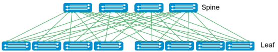
Figure 10. Leaf-Spine architecture
Design considerations
There are many different options regarding the selection of the correct topology that best fits the needs of the data center. In this section, the different protocols, topologies, and best practices are covered. The main differentiation is whether the Layer2/Layer3 boundary is located at the spine layer or at the leaf layer. When compared to a Layer 3 topology, a Layer 2 topology is generally less complex but has some limitations that must be considered. These include:
- For each VLAN, the Layer 2 topology creates one large broadcast domain across the fabric. The Layer 3 topology has the benefit of containing broadcast domains to each rack.
- The Layer 2 topology is limited to 4094 VLANs across the fabric. The Layer 3 topology allows up to 4094 VLANs per rack.
- The Layer 2 topology is limited to two physical switches at the spine layer (configured as VLT peers). In a Layer 3 topology, additional spines may be added as needed to provide additional paths and bandwidth. Therefore, a Layer 3 topology is more scalable and is better suited for large networks.
- If none of the Layer 2 limitations are a concern, it may be just a matter of preference. This guide provides examples of both topologies.
In addition to the considerations for the L2 topology, some options also need to be considered in the L3 topology. The primary design choice is in the dynamic routing protocol that best fits the environment. BGP may be selected for scalability and is well suited for very large networks, while OSPF is an interior gateway protocol that provides routing inside an autonomous network. OSPF routers send link-state advertisements to all other routers within the same autonomous system areas. This generally causes more memory and CPU usage than BGP. However, OSPF may offer faster convergence. OSPF is often used in smaller networks.
Design choices that are common in both topologies include:
- Whether to use LACP or non-LACP configurations downstream.
- Configuring each leaf pair in a Virtual Link Trunking (VLT).
- Dell EMC recommends that RSTP is always configured as a best practice. Although configuring VLT creates a loop-free topology, RSTP prevents loops in the case of a misconfiguration in the network.
Oversubscription
Oversubscription is equal to the total amount of bandwidth available to all servers connected to a leaf switch, divided by the amount of uplink bandwidth. In a leaf-spine network, oversubscription occurs at the leaf layer.
Oversubscription = total bandwidth / uplink bandwidth
Other configurations use available servers, storage, and leaf switches that also could be used to manage the subscription rates. The following are examples of oversubscription ratios based on downlink/uplink bandwidth.
Table 1. Oversubscription ratios based on uplink/downlink availability
NIC speed
Number of servers/storage interfaces/leafs
Total host bandwidth/leaf
Number of spines
Spine uplink speed
Total uplink bandwidth
Downlink/uplink bandwidth
Oversub-scription ratio
10 GbE
19
190 GbE
2
40 GbE
80 GbE
190/80
2.375 : 1
10 GbE
19
190 GbE
3
40 GbE
120 GbE
190/120
1.583 : 1
10 GbE
19
190 GbE
4
40 GbE
160 GbE
190/160
1.187 : 1
10 GbE
38
380 GbE
2
40 GbE
80 GbE
380/80
4.750 : 1
10 GbE
38
380 GbE
3
40 GbE
120 GbE
380/120
3.167 : 1
10 GbE
38
380 GbE
4
40 GbE
160 GbE
380/160
2.375 : 1
10 GbE
38
380 GbE
2
100 GbE
80 GbE
380/200
1.900 : 1
10 GbE
38
380 GbE
3
100 GbE
120 GbE
380/300
1.267 : 1
10 GbE
38
380 GbE
4
100 GbE
160 GbE
380/400
0.950 : 1