
Layer 3 topology preparation
Layer 3 topology preparation
-
The Layer 3 topology used in this example uses external border gateway protocol (eBGP) as well as ECMP. In order to correctly configure this topology, several things must be considered and planned.
BGP ASN configuration
When eBGP is used, an autonomous system number (ASN) is assigned to each switch. Valid private, 2-byte ASNs range from 64512 through 65534. The following figure shows the ASN assignments used for leaf and spine switches in the BGP examples in this guide:
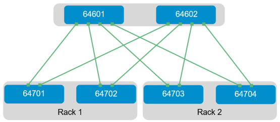
Figure 14. BGP ASN assignments
ASNs should follow a logical pattern for ease of administration and allow for growth as additional leaf and spine switches are added. In this example, an ASN with a 6 in the hundreds place represents a spine switch (for example, 64601), and an ASN with a 7 in the hundreds place represents a leaf switch (for example, 64701).
Note: The same ASN can be used across all tier-2 spine switches if the growth plans do not require an additional layer of spine switches.
Loopback addresses
Loopback addresses may be used as router IDs when configuring routing protocols. As with ASNs, loopback addresses should follow a logical pattern that makes it easier for administrators to manage the network and allow for growth. The following figure shows the loopback addresses used as router IDs in the example provided:
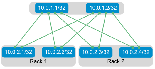
Figure 15. Loopback addressing
All loopback addresses used are part of the 10.0.0.0/8 address space, with each address using a 32-bit mask. In this example, the third octet represents the layer, 1 for the spine and 2 for the leaf. The fourth octet is the counter for the appropriate layer. For example, 10.0.1.1/32 is the first spine switch in the topology while 10.0.2.4/32 is the fourth leaf switch.
Point-to-point interfaces
The following table lists Layer 3 connection details for each leaf and spine switch.
All addresses come from the same base IP prefix, 192.168.0.0/16, with the third octet representing the spine number. For example, 192.168.1.0/31 is a two-host subnet connected to Spine 1, while 192.168.2.0/31 is connected to Spine 2. This IP scheme is easily extended as leaf and spine switches are added to the network.
Link labels are provided in the table for quick reference with the following figure.
Table 3. Interface and IP configuration
Link label
Source switch
Source interface
Source IP
Network
Destination switch
Destination interface
Destination IP
A
Leaf 1
Eth1/1/49
.1
192.168.1.0/31
Spine 1
Eth1/1/1
.0
B
Leaf 1
Eth1/1/50
.1
192.168.2.0/31
Spine 2
Eth1/1/1
.0
C
Leaf 2
Eth1/1/49
.3
192.168.1.2/31
Spine 1
Eth1/1/2
.2
D
Leaf 2
Eth1/1/50
.3
192.168.2.2/31
Spine 2
Eth1/1/2
.2
E
Leaf 3
Eth1/1/49
.5
192.168.1.4/31
Spine 1
Eth1/1/3
.4
F
Leaf 3
Eth1/1/50
.5
192.168.2.4/31
Spine 2
Eth1/1/3
.4
G
Leaf 4
Eth1/1/49
.7
192.168.1.6/31
Spine 1
Eth1/1/4
.6
H
Leaf 4
Eth1/1/50
.7
192.168.2.6/31
Spine 2
Eth1/1/4
.6
The point-to-point IP addresses used in this guide are shown in the following figure:
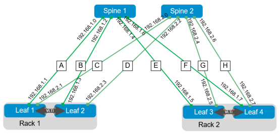
Figure 16. Point-to-point IP addresses