
Layer 2 topology configurations
Layer 2 topology configurations
-
This section covers the configuration of the Layer 2 topology. In the example provided, there are three Isilon nodes connected to each leaf pair, as well as two Dell PowerEdge servers that consume the storage. The connections from the spine switches to the OS10EE leaf pair are configured in port channel 49, while the connections to the OS9 leaf pair are configured in port channel 50. The two spine switches are configured in a VLT. The benefits and drawbacks of an L2 configuration are discussed in Design considerations. All the Isilon nodes connect to each switch in the leaf pair using an LACP port channel for each node, and the connections for the Windows servers are similarly configured. Also, each Isilon Node is connected on the back-end network through two InfiniBand switches, creating one single six-node cluster.
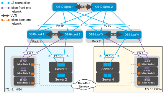
Figure 21. L2 topology
Note: The configuration files for every switch in this topology are provided in the Configuration Files section at the end of this document.
Configuration of Z9100-ON OS10EE spine switches
The configuration of the example used in this guide begins with the two Z9100-ONs Spine1 and Spine2, as seen in the following figure:
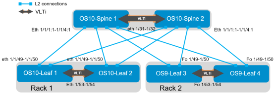
Figure 22. OS10EE spine
Set the hostname and configure the OOB management interface and default gateway. Additionally, with the spine switches configured in a VLT pair, RSTP is configured at the spine layer. The priority for RSTP is set on each spine switch. This ensures that the root bridge is always one of the spine switches.
Z9100-ON Spine 1
Z9100-ON Spine 2
configure terminal
hostname Z9100-Spine1
interface mgmt 1/1/1
no ip address dhcp
no shutdown
ip address 100.67.169.37/24
management route 0.0.0.0/0 100.67.169.254
spanning-tree mode rstp
spanning-tree rstp priority 0
configure terminal
hostname Z9100-Spine2
interface mgmt 1/1/1
no ip address dhcp
no shutdown
ip address 100.67.169.36/24
management route 0.0.0.0/0 100.67.169.254
spanning-tree mode rstp
spanning-tree rstp priority 4096
First, configure the VLT on each spine switch. Once VLT is enabled, it dynamically changes the MTU settings for the VLTi to a value of 9216.
Z9100-ON Spine 1
Z9100-ON Spine 2
interface range ethernet1/1/31-1/1/32
description VLTi
no shutdown
no switchport
vlt-domain 127
backup destination 100.67.169.36
discovery-interface ethernet1/1/31-1/1/32
peer-routing
interface range ethernet1/1/31-1/1/32
description VLTi
no shutdown
no switchport
vlt-domain 127
backup destination 100.67.169.37
discovery-interface ethernet1/1/31-1/1/32
peer-routing
Next, configure the required VLANs on each spine switch. There is one VLAN assigned for each of the subnets that are defined as seen in Figure 21. VRRP is used to ensure availability in the event of a switch failure. The priority is set to 150 on spine 1 to ensure that it is the VRRP master.
Z9100-ON Spine 1
Z9100-ON Spine 2
interface vlan100
no shutdown
mtu 9216
ip address 172.16.1.252/24
vrrp-group 100
priority 150
virtual-address 172.16.1.254
interface vlan200
no shutdown
mtu 9216
ip address 172.16.2.252/24
vrrp-group 200
priority 150
virtual-address 172.16.2.254
interface vlan100
no shutdown
mtu 9216
ip address 172.16.1.253/24
vrrp-group 100
priority 100
virtual-address 172.16.1.254
interface vlan200
no shutdown
mtu 9216
ip address 172.16.2.253/24
vrrp-group 200
priority 100
virtual-address 172.16.2.254
Configure the port channels between the spine and leaf switches. There are four connections from each spine to the leaf switches. Port channel 49 is configured on the OS10EE leaf pair, and port channel 50 is configured on the OS9 leaf pair. Also, the downstream switches are S4048-ON switches with 40 GbE uplinks. Each of the connections from the Z9100-ON spines to the S4048-ON leaf switches must have the speed set to 40 GbE.
Z9100-ON Spine 1
Z9100-ON Spine 2
interface breakout 1/1/1 map 40g-1x
interface breakout 1/1/2 map 40g-1x
interface breakout 1/1/3 map 40g-1x
interface breakout 1/1/4 map 40g-1x
interface port-channel49
description R1-Leaf-AandB
no shutdown
switchport mode trunk
switchport trunk allowed vlan 100
mtu 9216
vlt-port-channel 49
interface port-channel50
description R2-Leaf-AandB
no shutdown
switchport mode trunk
switchport trunk allowed vlan 200
mtu 9216
vlt-port-channel 50
interface ethernet1/1/1:1
description R1-Leaf-A
no shutdown
no switchport
channel-group 49 mode active
mtu 9216
interface ethernet1/1/2:1
description R1-Leaf-B
no shutdown
no switchport
channel-group 49 mode active
mtu 9216
interface ethernet1/1/3:1
description R2-Leaf-A
no shutdown
no switchport
channel-group 50 mode active
mtu 9216
interface ethernet1/1/4:1
description R2-Leaf-B
no shutdown
no switchport
channel-group 50 mode active
mtu 9216
end
write memory
Finally, exit configuration mode and save the configuration.
Configuration of S4048-ON OS10EE leaf switches
Leaf 1 and Leaf 2 running OS10EE are configured next, as shown in the following figure:
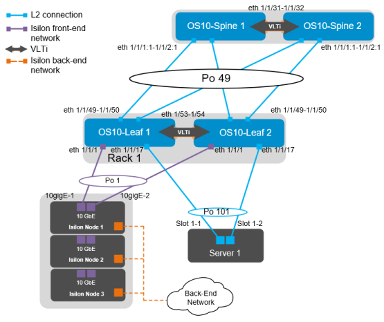
Figure 23. OS10EE leaf pair
The interfaces for additional Isilon nodes and servers in this example are listed in the following table:
Table 6. Interface enumeration
Server/Isilon node
Switch
Leaf interface
Node 01-1
Leaf 1
ethernet 1/1/1
Leaf 2
ethernet 1/1/1
Node 01-2
Leaf 1
ethernet 1/1/3
Leaf 2
ethernet 1/1/3
Node 01-3
Leaf 1
ethernet 1/1/5
Leaf 2
ethernet 1/1/5
Server 01
Leaf 1
ethernet 1/1/17
Leaf 2
ethernet 1/1/17
Server 02
Leaf 1
ethernet 1/1/19
Leaf 2
ethernet 1/1/19
First, set the hostname and configure the OOB management interface and default gateway. Enable RSTP as a precaution for network loops. The RSTP priority is set at the spine layer, and each leaf switch is left at the default value for RSTP. The no iscsi enable command is issued to ensure that iSCSI snooping is disabled.
S4048-ON Leaf 1
S4048-ON Leaf 2
configure terminal
hostname S4048-Leaf1
interface mgmt 1/1/1
no ip address dhcp
ip address 100.67.170.15/24
management route 0.0.0.0/0 100.67.170.254
no iscsi enable
configure terminal
hostname S4048-Leaf2
interface mgmt 1/1/1
no ip address dhcp
ip address 100.67.170.14/24
management route 0.0.0.0/0 100.67.171.254
no iscsi enable
Configure the VLT interconnect between S4048-Leaf1 and S4048-Leaf2. In this configuration, remove each interface from Layer 2 mode with the no switchport command for interfaces eth 1/1/53–1/1/54. Once this is done, enter the VLT domain, add the backup destination, and add the interfaces participating in VLTi. Finally, enable VLT peer routing on each switch. Once VLT is enabled, it dynamically changes the MTU settings for the VLTi to a value of 9216. Isilon’s OneFS supports and recommends the use of jumbo frames.
Note: Refer to Dell EMC Isilon: Network Design Considerations for more information about specific protocols as they relate to OneFS.
S4048-ON Leaf 1
S4048-ON Leaf 2
interface range ethernet 1/1/53-1/1/54
description VLTi
no switchport
no shutdown
vlt-domain 127
backup destination 100.67.170.14
discovery-interface ethernet 1/1/53-1/1/54
interface range ethernet 1/1/53-1/1/54
description VLTi
no switchport
no shutdown
vlt-domain 127
backup destination 100.67.170.15
discovery-interface ethernet 1/1/53-1/1/54
Next, create the VLANs. IP addresses and VRRP are configured at the spine layer. On each leaf switch, the respective VLAN is defined without an IP address or VRRP.
S4048-ON Leaf 1
S4048-ON Leaf 2
interface vlan100
no shutdown
interface vlan100
no shutdown
Configure the downstream port channels. There is one port channel for each server, as well as a single port channel for each of the Isilon nodes. Each port channel is assigned an MTU of 9216 to support jumbo frames, and each is configured to allow access to VLAN 100. The vlt-port-channel # command enables port channels on VLT peers to function as a single port channel.
S4048-ON Leaf 1
S4048-ON Leaf 2
interface port-channel1
description “Isilon Node 1”
no shutdown
switchport access vlan 100
mtu 9216
vlt-port-channel 1
spanning-tree port type edge
interface port-channel3
description “Isilon Node 2”
no shutdown
switchport access vlan 100
mtu 9216
vlt-port-channel 3
spanning-tree port type edge
interface port-channel5
description “Isilon Node 3”
no shutdown
switchport access vlan 100
mtu 9216
vlt-port-channel 5
spanning-tree port type edge
interface port-channel101
description “Server 1”
no shutdown
switchport access vlan 100
mtu 9216
vlt-port-channel 101
spanning-tree port type edge
interface port-channel102
description “Server 2”
no shutdown
switchport access vlan 100
mtu 9216
vlt-port-channel 102
spanning-tree port type edge
The downstream interfaces are configured in the next section. Dell recommends asymmetrical flow control (rx on tx off) on S4048-ON leaf switches which have sufficient egress buffers to reduce packet drops and resulting retransmissions. This feature is applied on all host interfaces that support flow control. In OS10EE, this is enabled by default, while in OS9 it must be configured. Flow control commands are added below for reference; however, they are not required in OS10EE.
S4048-ON Leaf 1
S4048-ON Leaf 2
interface ethernet1/1/1
description “Isilon Node 1-10gige-1”
no shutdown
channel-group 1 mode active
no switchport
mtu 9216
flowcontrol receive on
flowcontrol transmit off
interface ethernet1/1/3
description “Isilon Node 2-10gige-1”
no shutdown
channel-group 3 mode active
no switchport
mtu 9216
flowcontrol receive on
flowcontrol transmit off
interface ethernet1/1/5
description “Isilon Node 3-10gige-1”
no shutdown
channel-group 5 mode active
no switchport
mtu 9216
flowcontrol receive on
flowcontrol transmit off
interface ethernet1/1/17
description “Server 1-1”
no shutdown
channel-group 101 mode active
no switchport
mtu 9216
flowcontrol receive on
flowcontrol transmit off
interface ethernet1/1/19
description “Server 2-1”
no shutdown
channel-group 102 mode active
no switchport
mtu 9216
flowcontrol receive on
flowcontrol transmit off
interface ethernet1/1/1
description “Isilon Node 1-10gige-2”
no shutdown
channel-group 1 mode active
no switchport
mtu 9216
flowcontrol receive on
flowcontrol transmit off
interface ethernet1/1/3
description “Isilon Node 2-10gige-2”
no shutdown
channel-group 3 mode active
no switchport
mtu 9216
flowcontrol receive on
flowcontrol transmit off
interface ethernet1/1/5
description “Isilon Node 3-10gige-2”
no shutdown
channel-group 5 mode active
no switchport
mtu 9216
flowcontrol receive on
flowcontrol transmit off
interface ethernet1/1/17
description “Server 1-2”
no shutdown
channel-group 101 mode active
no switchport
mtu 9216
flowcontrol receive on
flowcontrol transmit off
interface ethernet1/1/19
description “Server 2-2”
no shutdown
channel-group 102 mode active
no switchport
mtu 9216
flowcontrol receive on
flowcontrol transmit off
Next, Configure the upstream port channels as well as the corresponding interfaces.
S4048-ON Leaf 1
S4048-ON Leaf 2
interface port-channel49
description “Spine 1”
no shutdown
switchport mode trunk
switchport trunk allowed vlan 100
mtu 9216
vlt-port-channel 49
interface ethernet1/1/49
description “Spine 1”
no shutdown
no switchport
channel-group 49 mode active
mtu 9216
interface ethernet1/1/50
description “Spine 2”
no shutdown
no switchport
channel-group 49 mode active
mtu 9216
Uplink Failure Detection (UFD) is configured next. UFD is a feature that shuts down specified downstream interfaces when all specified uplinks become disabled.
S4048-ON Leaf 1
S4048-ON Leaf 2
uplink-state-group 1
enable
downstream port-channel1
downstream port-channel3
downstream port-channel5
downstream port-channel101
downstream port-channel102
upstream port-channel49
end
write memory
uplink-state-group 1
enable
downstream port-channel1
downstream port-channel3
downstream port-channel5
downstream port-channel101
downstream port-channel102
upstream port-channel49
end
write memory
Finally, exit configuration mode and save the configuration.
Configuration of S4048-ON OS9 leaf switches
Configurations in this section cover the leaf switches 3 and 4 running OS9, as shown in the following figure:
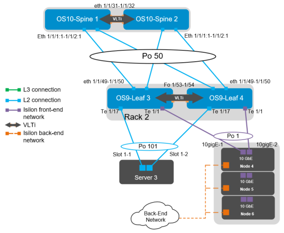
Figure 24. OS9 leaf pair
The ports for additional Isilon nodes and servers in this example are listed in the following table:
Table 7. Interface enumeration
Server/Isilon node
Switch
Leaf interface
Node 01-4
Leaf 3
tengigabitethernet 1/1/1
Leaf 4
tengigabitethernet 1/1/1
Node 01-5
Leaf 3
tengigabitethernet 1/1/3
Leaf 4
tengigabitethernet 1/1/3
Node 01-6
Leaf 3
tengigabitethernet 1/1/5
Leaf 4
tengigabitethernet 1/1/5
Server 03
Leaf 3
tengigabitethernet 1/1/17
Leaf 4
tengigabitethernet 1/1/17
Server 04
Leaf 3
tengigabitethernet 1/1/19
Leaf 4
tengigabitethernet 1/1/19
First, set the hostname and configure the OOB management interface and default gateway. Next, enable LLDP and RSTP. In OS10EE, LLDP is enabled by default; while in OS9, it must be enabled.
S4048-ON Leaf 3
S4048-ON Leaf 4
configure terminal
hostname S4048-Leaf3
interface management 1/1
ip address 100.67.171.15/24
no shutdown
management route 0.0.0.0/0 100.67.171.254
protocol lldp
advertise management-tlv management- address system-description system-name
advertise interface-port-desc
protocol spanning-tree rstp
no disable
configure terminal
hostname S4048-Leaf4
interface management 1/1
ip address 100.67.171.15/24
no shutdown
management route 0.0.0.0/0 100.67.171.254
protocol lldp
advertise management-tlv management- address system-description system-name
advertise interface-port-desc
protocol spanning-tree rstp
no disable
Configure the VLT interconnect between S4048-Leaf3 and S4048-Leaf4. Create a static port channel and add the two VLTi connections to port channel 128. Configure the VLT domain using the management interface of the peer switch as the backup destination. The backup destination is only utilized for the VLT heartbeat. The unit-id # command designates the primary VLT member. Once VLT is enabled, it dynamically changes the MTU settings for the VLTi to a value of 9216. Isilon’s OneFS supports and recommends the use of jumbo frames.
S4048-ON Leaf 3
S4048-ON Leaf 4
interface port-channel128
description VLTi
channel-member fortyGigE 1/53
channel-member fortyGigE 1/54
no shutdown
no switchport
interface fortyGigE 1/53
description VLTi
no shutdown
no switchport
interface fortyGigE 1/54
description VLTi
no shutdown
no switchport
vlt domain 127
peer-link port-channel 128
back-up destination 100.67.171.14
unit-id 0
interface port-channel128
description VLTi
channel-member fortyGigE 1/53
channel-member fortyGigE 1/54
no shutdown
no switchport
interface fortyGigE 1/53
description VLTi
no shutdown
no switchport
interface fortyGigE 1/54
description VLTi
no shutdown
no switchport
vlt domain 127
peer-link port-channel 128
back-up destination 100.67.171.15
unit-id 1
Note: When port channel 128 is added to the vlt domain, the MTU setting is automatically changed to 9216.
The downstream interfaces are configured in the next section. Dell recommends asymmetrical flow control (rx on tx off) on S4048-ON leaf switches which have sufficient egress buffers to reduce packet drops and resulting retransmissions. This feature is applied on all host interfaces that support flow control. In OS10EE, this is enabled by default; while in OS9, it must be configured. Flow Control is configured with the flowcontrol rx on tx off command.
S4048-ON Leaf 3
S4048-ON Leaf 4
interface tengigabitethernet 1/1
description “Isilon Node 4-10gige-1”
no shutdown
port-channel-protocol LACP
port-channel 1 mode active
mtu 9216
flowcontrol rx on tx off
interface tengigabitethernet 1/3
description “Isilon Node 5-10gige-1”
no shutdown
port-channel-protocol LACP
port-channel 3 mode active
mtu 9216
flowcontrol rx on tx off
interface tengigabitethernet 1/5
description “Isilon Node 6-10gige-1”
no shutdown
port-channel-protocol LACP
port-channel 5 mode active
mtu 9216
flowcontrol rx on tx off
interface tengigabitethernet 1/17
description “Server 3-1”
no shutdown
port-channel-protocol LACP
port-channel 101 mode active
mtu 9216
flowcontrol rx on tx off
interface tengigabitethernet 1/19
description “Server 4-1”
no shutdown
port-channel-protocol LACP
port-channel 102 mode active
mtu 9216
flowcontrol rx on tx off
interface tengigabitethernet 1/1
description “Isilon Node 4-10gige-2”
no shutdown
port-channel-protocol LACP
port-channel 1 mode active
mtu 9216
flowcontrol rx on tx off
interface tengigabitethernet 1/3
description “Isilon Node 5-10gige-2”
no shutdown
port-channel-protocol LACP
port-channel 3 mode active
mtu 9216
flowcontrol rx on tx off
interface tengigabitethernet 1/5
description “Isilon Node 6-10gige-2”
no shutdown
port-channel-protocol LACP
port-channel 5 mode active
mtu 9216
flowcontrol rx on tx off
interface tengigabitethernet 1/17
description “Server 3-2”
no shutdown
port-channel-protocol LACP
port-channel 101 mode active
mtu 9216
flowcontrol rx on tx off
interface tengigabitethernet 1/19
description “Server 4-2”
no shutdown
port-channel-protocol LACP
port-channel 102 mode active
mtu 9216
flowcontrol rx on tx off
Configure the necessary downstream port channels. There is one port channel for each server, as well as a single port channel for each of the Isilon nodes. Each port channel is assigned an MTU of 9216 to support jumbo frames. The vlt-peer-lag-port-channel # command ensures that each switch in the VLT is aware of all port channels and can act accordingly in the event of a switch failure.
S4048-ON Leaf 3
S4048-ON Leaf 4
interface port-channel1
description “Isilon Node 4”
no shutdown
switchport
mtu 9216
vlt-peer-lag port-channel 1
spanning-tree rstp edge-port
interface port-channel3
description “Isilon Node 5”
no shutdown
switchport
mtu 9216
vlt-peer-lag port-channel 3
spanning-tree rstp edge-port
interface port-channel5
description “Isilon Node 6”
no shutdown
switchport
mtu 9216
vlt-peer-lag port-channel 5
spanning-tree rstp edge-port
interface port-channel101
description “Server 3”
no shutdown
switchport
mtu 9216
vlt-peer-lag port-channel 101
spanning-tree rstp edge-port
interface port-channel102
description “Server 4”
no shutdown
switchport
mtu 9216
vlt-peer-lag port-channel 102
spanning-tree rstp edge-port
The upstream interfaces and port channels are configured as follows:
S4048-ON Leaf 3
S4048-ON Leaf 4
interface port-channel50
description “Spine 1 and 2”
no shutdown
switchport
mtu 9216
vlt-peer-lag port-channel 50
interface fo 1/49
description “Spine 1”
no shutdown
port-channel-protocol LACP
port-channel 50 mode active
mtu 9216
interface fo 1/50
description “Spine 2”
no shutdown
port-channel-protocol LACP
port-channel 50 mode active
mtu 9216
Next, create the VLANs. There is one VLAN for each Isilon subnet, and this also includes the servers in each rack.
S4048-ON Leaf 3
S4048-ON Leaf 4
interface vlan200
no shutdown
untagged port-channel 1,3,5,101,102
tagged port-channel 50
interface vlan200
no shutdown
untagged port-channel 1,3,5,101,102
tagged port-channel 50
Uplink Failure Detection (UFD) is configured next. UFD shuts down all downstream interfaces if all uplinks fail.
S4048-ON Leaf 3
S4048-ON Leaf 4
uplink-state-group 1
downstream port-channel1
downstream port-channel3
downstream port-channel5
downstream port-channel101
downstream port-channel102
upstream port-channel 50
end
write memory
uplink-state-group 1
downstream port-channel1
downstream port-channel3
downstream port-channel5
downstream port-channel101
downstream port-channel102
upstream port-channel 50
end
write memory
Finally, exit configuration mode and save the configuration with the end and write commands.