
Configuration procedure
Configuration procedure
-
The following section outlines the steps necessary to add the Isilon X210 nodes into a cluster, set up a functioning SMB share, designate a secondary subnet, and configure the SmartConnect feature in OneFS.
Building the cluster
The first step in configuring the Isilon array is building the cluster. Once the array is powered on, a serial connection can be made to each node. Connect to the first node and use the cluster creation wizard to build the cluster. Table 8 shows the values that are used in this example. If any additional information is needed on the setup and configuration of the Isilon Array cluster, refer to the Isilon X210 Installation Guide.
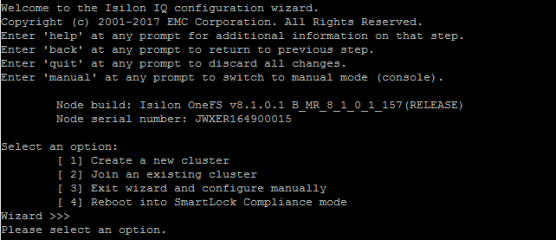
Figure 25. Initial configuration wizard
The following table outlines the configurations in this example. The following configurations are discussed in this section:
- The cluster name is defined.
- IP ranges are assigned for the back-end network.
- Configuration of the management 1 GbE ext-1 connections are made using OOB management IP range 100.67.170.0/24.
The 10gige-1 and 10gige-2 interfaces for user connectivity are configured in the next section.
Table 8. Isilon configuration parameters
Parameter
Value
Option
[ 1] Create a new cluster
Configure root/admin passwords
"password"
Configuration Name
Cluster-01
Cluster Encoding
[ 8] UTF-8
Interface int-a netmask
255.255.255.0
Interface int-a IP Range
10.10.10.1-253
Interface int-b netmask
255.255.255.0
Interface int-b IP Range
10.10.20.1-253
Failover IP range
10.10.30.1-253
Interface ext-1 netmask
255.255.255.0
MTU
1500
Interface ext-1 IP pool
100.67.170.140-148
ext-1 default gateway
100.67.170.254
SmartConnect Zone name
Mgmtzone1
SmartConnect service IP
100.67.170.149
DNS servers
100.67.10.1
Search domain
dell.local
Cluster date and time
Default
Cluster join mode
Default
Commit changes
Yes
Note: Additional information and configuration for SmartConnect are provided in Setting up DNS for SmartConnect.
When the first node is configured and the cluster has been created, the other nodes can then be added into the cluster. All nodes can discover the cluster over the back-end network. The assorted options for back-end networking and Isilon are not covered in this document. For more information on the back-end network, refer to Isilon documentation.
To join a cluster, perform the following steps:
- At the login screen of node two, select [ 2] Join existing cluster.
- The cluster that was created is displayed, select 1 to add node two to Cluster-01.
- Repeat for all nodes to be added to the cluster. Each node is dynamically assigned an IP address out of the IP pool that was designated in the cluster creation.
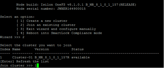
Figure 26. Join cluster
Configuring LACP to each node
Once the cluster has been created, and each node has been added to the cluster, the rest of the configurations can be done through the OneFS web GUI. This section covers the creation of two subnets and their associated IP pools, as well as the addition of static routes to ensure end-to-end connectivity. This includes ensuring that the LACP option is selected and that the appropriate interfaces are selected.
- Navigate to a web page using the first IP address in the range defined for the ext-1 interface, https://100.67.170.140:8080. This brings you to the first node in the cluster.
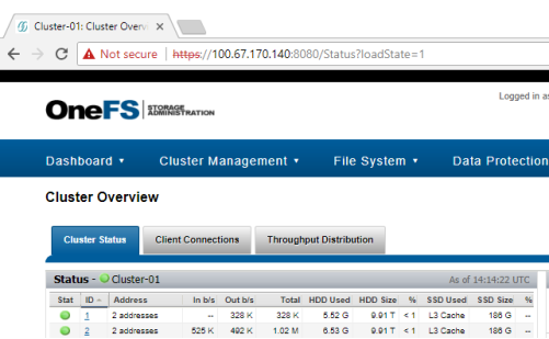
Figure 27. OneFS Web GUI
- Log in to the OneFS web GUI and navigate to Cluster Management > Network Configuration. This allows changes to the network configuration.
- Select the More option next to groupnet0 and click Add subnet. Define values for the next two subnets. Refer to the following table:
Table 9. Subnet configurations
Parameter
Value
Subnet Name
subnet1
Netmask
255.255.255.0
Gateway Address
172.16.1.254
MTU
9000(Jumbo Frame)
SmartConnect Service IP
172.16.1.249
SmartConnect Service Name
sczone1.dell.local
Subnet Name
subnet2
Netmask
255.255.255.0
Gateway Address
172.16.2.254
MTU
9000(Jumbo Frame)
SmartConnect Service IP
172.16.2.249
SmartConnect Service Name
sczone2.dell.local
- Select the More option next to subnet1, and click Add pool.
- Define the pool name, pool1.
- Set the IP range, 172.16.1.1-50.
- Add in the 10gige-agg-1 interfaces for nodes 1–3 into the pool.
- Set the SmartConnect Zone name, sczone1.
- Set the SmartConnect Service subnet, subnet1.
- Ensure that the Aggregation Mode is set to LACP.
- Complete steps 4 through 10 to create pool2 in subnet2.
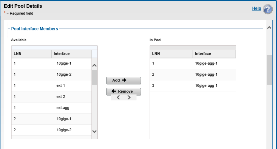
Figure 28. LACP configuration
The next section covers the configuration of static routes within OneFS. This is necessary to enable traffic to cross between the two subnets.
- Navigate to Network configurations > subnet1 > pool1, and then add a static route to subnet 2.
Parameter
Value
Subnet
172.16.2.0
Netmask
255.255.255.0
Gateway
172.16.1.254
- Navigate to Network configurations > subnet2 > pool2, and then add a static route to subnet 1.
Parameter
Value
Subnet
172.16.1.0
Netmask
255.255.255.0
Gateway
172.16.2.254
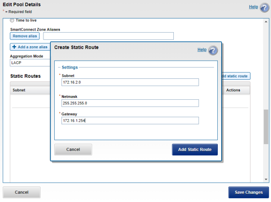
Figure 29. Static routes
In addition to the Isilon nodes, each Windows server is configured in an LACP NIC team that utilizes the address hash setting. The specific configuration steps for a Windows NIC team can be found in Microsoft’s documentation, Create a New NIC Team on a Host Computer or VM.
Configuring SMB share
This section covers the creation of a folder structure that is configured under OneFS Protocols Windows Sharing SMB. Once the folders are added to the Windows Sharing SMB section and the network is properly configured, the folder is accessible through a Windows server.
- From the OneFS GUI, select File System > File System Explorer.
- Select Create Directory.
- Define the directory name (SMB), as well as the user, group, and permission settings as shown:
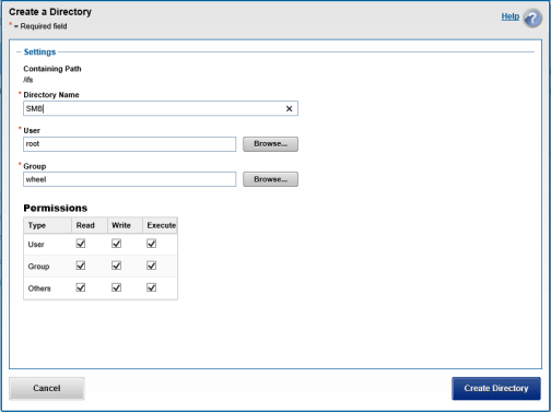
Figure 30. Directory creation
- Once the folder has been created, click the SMB folder.
- Once again, create a directory and assign the name (Engineering), user, group, and permissions settings.
- When both folders have been created, navigate to the Protocols > Windows Sharing (SMB).
- Select Create an SMB Share.
- Assign a name (Engineering SMB), and use the Browse button to navigate to the Engineering folder that was created previously.
- Select the member's window and assign access permissions.
- All other selections are left at the default values.
- Click Create Share.
Setting up DNS for SmartConnect
One of the features of the OneFS file system is SmartConnect. SmartConnect allows the workload to be dynamically reassigned to other nodes in the cluster in the event of a node failure. SmartConnect is a feature that must be configured. There is also a DNS dependency for SmartConnect to function properly. Configuring DNS host A records and Delegation zones is necessary. Once this is done, SmartConnect assigns the workload to each node using the round robin method. Using the FQDN that was configured previously for the SmartConnect zones is required. This section covers the completion of the SmartConnect configuration.
- Log in to the DNS server.
Note: Refer to Microsoft's DNS Resource Record Management for the specific steps in creating a DNS server.
- Navigate to Server Manager > Tools > DNS and configure the following:
Table 10. DNS parameters
Parameter
Value
Forward Lookup Zone
dell.local
Reverse Lookup Zones
172.16.1, 172.16.2
Host A record for sczone1
sczonea, 172.16.1.249
Host A record for sczone2
sczoneb, 172.16.2.249
Delegation zone for sczone1
sczone1.dell.local, 172.16.1.249
Delegation zone for sczone2
sczone2.dell.local, 172.16.2.249
It is important that the DNS Host A record has a unique name that does not match the name that was assigned to the SmartConnect zone within the OneFS file system. The Delegation zone, however, needs a name that matches the SmartConnect zone. This ensures that a connection to sczone1.dell.local references the SmartConnect Zone 1 IP of 172.16.1.249. When this IP is referenced, it round robins through each node IP, assigning the workload to each node in turn, ensuring a balanced workload.