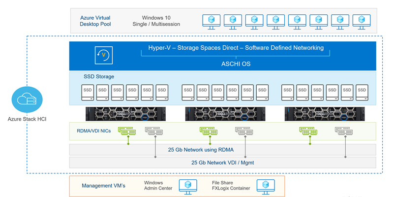
The hardware configuration outlined in this section focuses primarily on the AX-750 node that is configured to support VDI deployments. AX-750 nodes are based on Dell 15th Generation server technology with third-generation Intel® Xeon® dual-socket Intel Ice Lake processors.
The AX-750 comes in a 2U chassis format with capacity for 24 x 2.5" front bay drives. It is GPU-ready for single-width and double-width GPUs, though graphics are not included in this solution. The solution can scale from two to sixteen nodes.
The following figure shows the hardware configuration:

AX-750 nodes
The AX-750 is a 15th Generation PowerEdge based, capacity- and performance-optimized node for applications needing a balance of compute and storage. Benefits include:
- Excellent configuration flexibility and industry-leading energy efficiency.
- Capable of more than double the storage capacity of the AX-650 platform.
- High count of PCI slots for NIC and GPU upgrades (when available).
- BOSS-S2 support for hot-plug M.2 operating system drives.
The following table shows the configuration options available for AX-750 nodes:
| Features | AX-750 |
| CPU | Dual socket Intel Xeon Ice Lake EP processors (Silver/Gold/Platinum options) with 16 to 80 cores |
| Memory | 128 GB to 4 TB DDR4. Up to 3200 MT/s |
| Storage | 24 x 2.5" front bay drive chassis - All SSDs Storage for capacity min/max Minimum: 4 x 800 GB = 3.2 TB Maximum: 24 x 7.68 TB = 184 TB
BOSS S2 with Dual M.2 240 GB or 480 GB (RAID 1) |
| Storage Controller | Internal HBA 355i 12 Gbps SAS HBA Controller (NON-RAID) |
| Network | Integrated LOM: 2 x 1 GbE Base-T Broadcom Add-in-Card (required) Mellanox ConnectX-5 LX (Dual Port 25 GbE) Mellanox ConnectX-6 DX (Dual Port 100 GbE) (RDMA) OCP 3.0 Card (optional) Intel X710 Dual Port 10 GbE SFP+, OCP NIC 3.0 or Intel X710 Quad Port 10 GbE SFP+, OCP NIC 3.0 or Intel X710-T4L Quad Port 10 GbE BASE-T, OCP NIC 3.0 or Intel X710-T2L Dual Port 10 GbE BASE-T, OCP NIC 3.0 or Broadcom 57414 Dual Port 10/25 GbE SFP28, OCP NIC 3.0 or Broadcom 57504 Quad Port 10/25 GbE SFP28, OCP NIC 3.0 or Broadcom 57416 Dual Port 10 GbE BASE-T Adapter, OCP NIC 3.0 or Broadcom 57412 Dual Port 10 GbE SFP+, OCP NIC 3.0 |
| Riser/PCIe slots | Config 2 HL or FL - 4 x 16 +LP/FH + 2 X 8 FH PCIe Config 5 - 2 x 16 LP + 2 x 8 FH PCIe Config 1 - 2 x 16 PL + 6 x 8 FH PCIe |
| Integrated ports | Front: 2 x USB 2.0, 1 managed (micro-USB) + front VGA Rear: 1 x Gen2 + 1 x Gen3 USB Optional internal USB |
| System management | Windows Admin Center with Dell OpenManage Integration Integrated Dell Remote Access Controller (iDRAC) 9 Enterprise or Datacenter IPMI 2.0 compliant. Quick Sync2 (Optional) |
| High availability | Hot Plug redundant drives, 3-tiered hot plug fans, PSU, IDSDM, BOSS-S2 (2 x M.2) |
| Power supplies | Dual, hot-plug, redundant power supply (1+1), 1100/1400/2400 W |
| Form factor | 2U rack server |
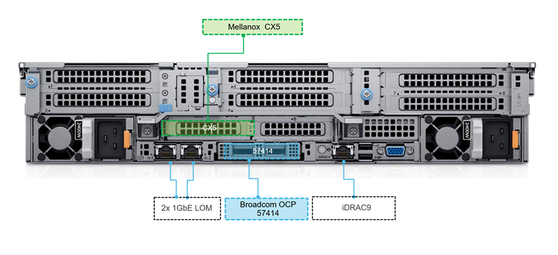
The following figures show front and rear views of the AX-750 node chassis:


VDI optimized configuration
Dell Technologies recommends the VDI Optimized AX-750 node configuration. This configuration provides a balance between high performance, high VDI user density and cost for VDI workloads.
| Platform | AX-750 |
| CPU | 2 x Intel Xeon Gold 6342 (2.8 GHz, 24 cores, 230 Watt) |
| Memory | 1024 GB (16 x 64 GB) 3200 MT/s RDIMMs |
| Storage Ctrl | Dell HBA355i for 2.5" x 24 SAS/SATA Chassis |
| Boot device | BOSS-S2 controller card with 2 x M.2 240 GB (RAID 1) |
| Storage | 6 x 1.92 TB SSD vSAS Mixed Use 12 Gbps 512e 2.5" hot-plug |
| Network | Broadcom OCP 57414 (Dual Port 25 GbE) Mellanox Connect X-5 (Dual Port 25 GbE) |
| Chassis/riser | 2.5" chassis with up to 24 SAS/SATA Drives. Riser config 2, full length, 4 x 16, 2 x 8 slots |
| iDRAC | iDRAC9 Datacenter |
| Graphics | GPU enabled config |
| Power | 2 x 2400 W PSUs |
Dell Technologies recommends configuring the servers with all-flash single tier (SSD or NVMe) drives instead of hybrid drive configurations as it allows IT organizations to leverage benefits like reduced power consumption, physical rack space consumption, and power and cooling reduction.
| Storage controller | Boot device | Storage |
| Dell HBA355i for 2.5" x 24 SAS/SATA chassis | BOSS‐S2 controller card + with 2 M.2 240 GB (RAID 1) | 6 x 1.92 TB SSD vSAS Mixed Use 12 Gbps 512e 2.5in hot‐plug |
Network components
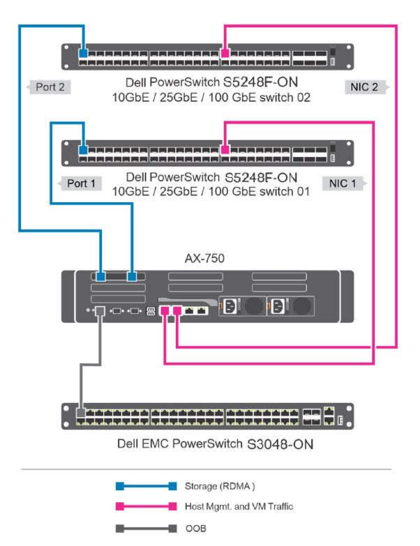
Network configurationThe Dell Technologies solution for Azure Stack HCI consists of two top-of-rack network switches that provide high availability by connecting the nodes to two separate network switches.
Network switchesTwo Dell PowerSwitch S5248F-ON switches are used as the top of rack network switches for this solution in a highly available configuration. The S5248F-ON switch is a 1U Top-of-rack (ToR) or leaf switch for environments requiring connectivity for 25 GbE and 10 GbE compute and storage.
This switch is part of the S5200-ON series of switches and is designed for in-rack 25 GbE connectivity. The PowerSwitch S5200-ON 25/100 GbE fixed switches consist of the latest disaggregated hardware and software data center networking solutions from Dell, providing state-of-the-art, high-density 25/100 GbE ports and a broad range of functionality.
The switch provides optimum flexibility and cost-effectiveness for demanding compute and storage traffic environments. This ToR switch features 48 x 25 GbE SFP28 ports, 4 x 100 GbE QSFP28 ports and 2 x 100 GbE QFSP28-DD ports. The S5248F-ON also supports Open Network Install Environment (ONIE) for zero-touch installation of network operating systems.
VDI validations have been successfully performed with this switch configuration.

For more information, see Dell Technologies Networking Switches and Switch configuration recommendations for iWARP-based deployments (converged and non-converged).
Non-converged network configurationThis solution uses a non-converged network configuration with separate network adapters used for storage traffic and management/VDI traffic. This configuration is scalable and supports from 2 to 16 nodes in a cluster.

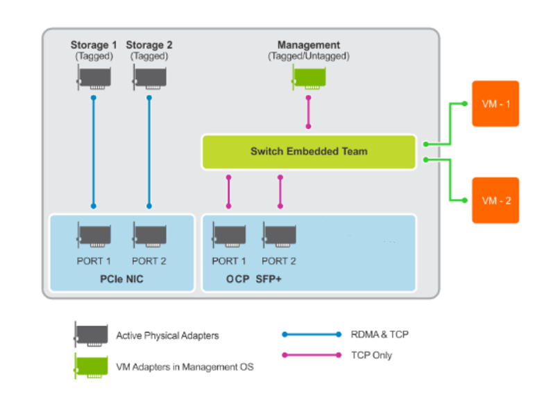
The OCP (rNDC) adapter ports are in a switch embedded teaming (SET) configuration and the add-in card adapters ports are left as physical adapters. With the non-converged configuration, Dell Technologies recommends that the storage traffic is on the physical storage network adapter ports, and management and VDI traffic through the SET-configured network adapter.

Azure Stack HCI also supports fully converged networking and switchless mesh networking topologies. In the fully converged network topology, all storage ports from the server are connected to the same network fabric with storage and management/VM traffic on the same network adapter.
Another option is switchless mesh networking which does not use a network switch for storage traffic transmission but instead requires a direct network cable connection between each node in the cluster. This configuration is not scalable.
For more information, see Reference Guide—Network Integration and Host Network Configuration Options.
Switch embedded teaming (SET)SET is a software-based teaming technology and is the only teaming technology that is supported by Azure Stack HCI. SET is not dependent on the type of network adapters used. Applicable traffic types can be VDI, storage, and management. In this architecture, the only adapter that is used for VDI and management network traffic has its ports added to an SET.
Network adaptersThe available network adapters for this solution can be divided into Mellanox add-in PCIe cards (required) and a range of OCP 3.0 (rNDC) adapters.
The Mellanox adapters are used for hosting storage traffic and employ RoCE (RDMA over Converged Ethernet). RDMA is a network stack offload to the network adapter that allows SMB storage traffic to bypass the operating system for processing. RDMA significantly increases throughput and lowers latency by performing direct memory transfers between servers.
The OCP adapters are used for hosting management and VDI traffic in the non-converged network configuration.
In the validated architecture, a Broadcom OCP 57414 network adapter’s ports are added to an SET for VDI and management traffic and a Mellanox Connect-X5 network adapter is used for storage traffic only. Other network card options are available for these functions and are detailed in the AX-750 node config.

RDMA is a network stack offload to the network adapter that allows SMB storage traffic to bypass the operating system for processing.
Mellanox network adapters implement RDMA using RoCE (RDMA over Converged Ethernet). When using RoCE, Data Center Bridging (DCB) must be enabled on the physical adapters in the non-converged topology. DCB provides enhancements to Ethernet communication with Priority Flow Control (PFC) and Enhanced Transmission Selection (ETS).
Priority flow control is used to prevent frame loss due to buffer overflows for selected traffic classes such as storage traffic. ETS is used to guarantee a minimum percentage of bandwidth for selected traffic classes.
Dell Technologies recommends that you use DCB (PFC/ETS) for all RoCE-based deployments on switch ports that are used for RDMA traffic.
To take advantage of the Mellanox network adapters, PFC and ETS are required. PFC and ETS must be configured on all nodes and all network switches interconnecting the nodes.
Another implementation of RDMA is iWARP, which is used on Qlogic network adapters. Decisions on the network card to use for storage traffic may depend on the suitability of using iWARP or RoCE to implement RDMA in the customer’s environment.
iWARP implements RDMA over IP networks using TCP, making it ideal for organizations that want to use RDMA over their existing IP network infrastructure without any specialized hardware. iWARP requires no additional configuration at the ToR switches for its implementation.
RoCEv2 uses UDP and requires QoS (Quality of Service) to ensure packet delivery. It relies on an Ethernet network that is configured to use Layer 2 Priority Flow Control (PFC) or Layer 3 DSCP PFC to minimize congestive packet loss.
For more information, see iWARP vs RoCE for RDMA.
QoSMellanox adapters require DCB configuration on the ToR switches and Quality of Service (QoS) configuration in the host operating system and ToR switches. The QoS policies are configured to prioritize the SMB traffic that is related to the storage adapters. The QoS configuration on the host operating system matches the QoS configuration of the network switches.
VLAN configurationThe following table shows a sample VLAN configuration that can be used with this solution:
| Traffic class | Purpose | VLAN ID | Untagged/Tagged |
| SMB Storage Traffic | Storage Network | 10 | Untagged/Tagged |
| SMB Storage Traffic | Storage Network | 11 | Untagged/Tagged |
| Management Traffic | Cluster Nodes Management | 102 | Untagged/Tagged |
| VDI Traffic | VDI Desktop VMS | 103 | Untagged/Tagged |
| iDRAC | Out-of-band Management | 104 | Untagged |
For more information, see the following documents:
Client components
Users can access the virtual desktops through various client components. The following table lists the client components that Dell Technologies recommends:
| Component | Description | Recommended use | More information |
| Latitude laptops and 2-and-1s |
|
| www.delltechnologies.com/Latitude |
| OptiPlex business desktops and All-in-Ones |
|
| www.delltechnologies.com/OptiPlex |
| Precision workstations |
|
| www.delltechnologies.com/Precision |
