Home > Integrated Products > VxRail > Guides > Planning Guide—VMware Cloud Foundation 5.1 on VxRail > BGP peering preparation
BGP peering preparation
-
Border Gateway Protocol (BGP) services on the Layer 2-3 network boundary should be configured before the initial deployment of Cloud Foundation on VxRail. Neighbor relationships upstream should be established to enable connectivity to required data center services and end-users, and to the external Dell Technologies and VMware support sites.
The tables in Appendix G: Edge gateway configuration provide guidance on the settings that must be captured to enable BGP peering with the NSX Tier-0 gateways for the Application Virtual Network.

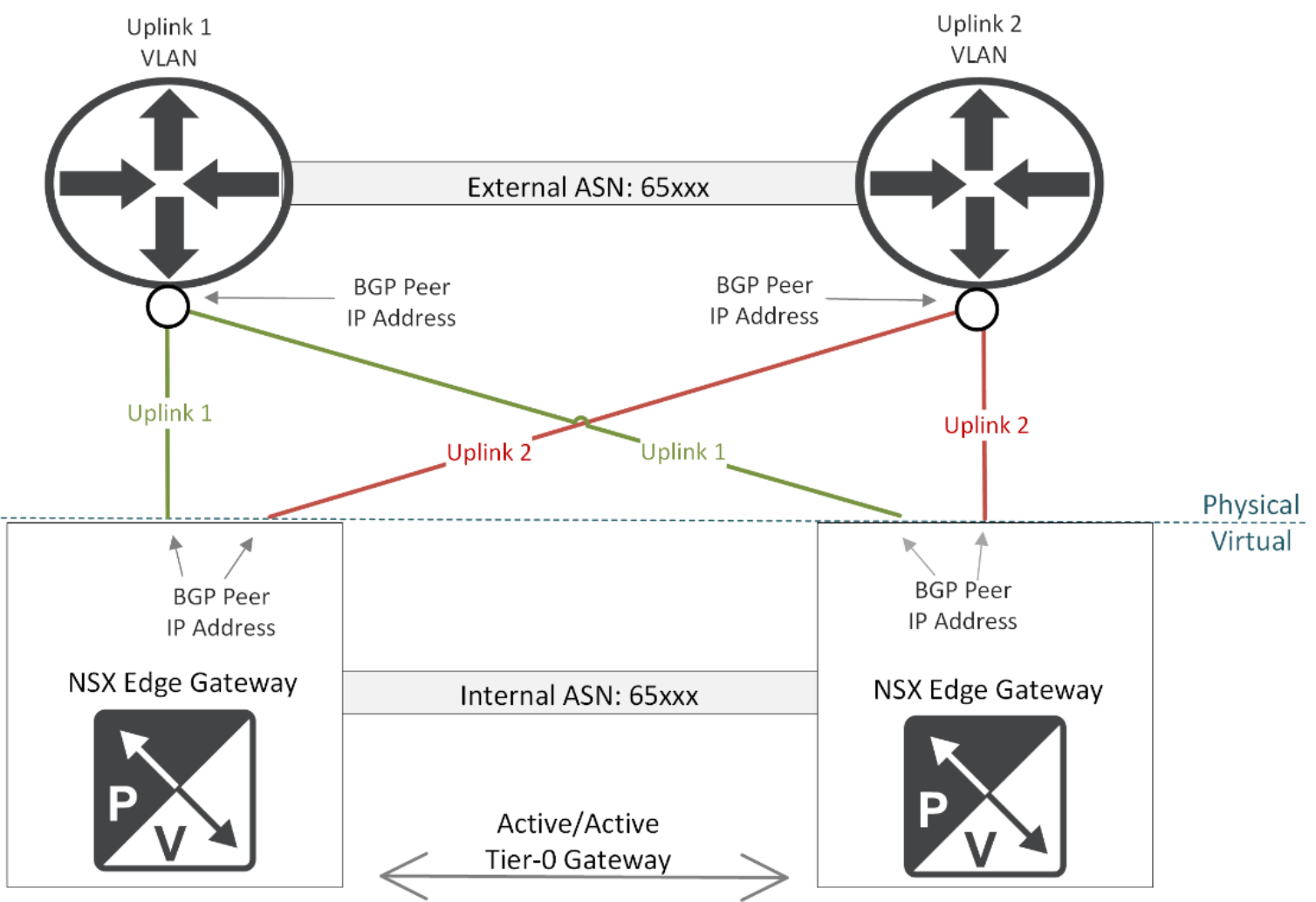
Figure 45. BGP relationship between NSX Edge Gateways and external routers
The NSX edge devices must be able to establish an eBGP peer relationship with upstream routing services. The following tasks must be completed on the upstream switches to enable peering with the NSX Edge Tier-0 gateways:
- BGP is configured on each router instance.
- Configure BGP with a common Autonomous System Number (ASN) on the network devices targeted for peering with the NSX edge gateways.
- Configure the IP prefix list to allow passage of all networks between the physical and virtual networks.
- Configure two eBGP neighbors on the first router instance.
- Configure the IP address assigned to the first uplink on the first NSX edge device for peering. This IP address is assigned to the first NSX edge uplink VLAN.
- Configure the IP address assigned to the first uplink on the second NSX edge device for peering. This uplink will also be assigned to the first NSX edge uplink VLAN.
- Configure the timer ‘keepalive’ value is to 4 and the timer ‘holdtime’ value to 12.
- Configure a password on the neighbor instance. This password is captured and configured on the adjacent NSX Tier-O gateways.
- Configure the internal ASN value assigned to the NSX edge devices.
- Configure two eBGP neighbors on the second router instance.
- Configure the IP address assigned to the second uplink on the first NSX edge device for peering. This IP address is assigned to the second NSX edge uplink VLAN.
- Configure the IP address assigned to the second uplink on the second NSX edge device for peering. This uplink will also be assigned to the second NSX edge uplink VLAN.
- Configure the timer ‘keepalive’ value is to 4 and the timer ‘holdtime’ value to 12.
- Configure a password on the neighbor instance. This password is captured and configured on the adjacent NSX Tier-0 gateways.
- Configure the internal ASN value assigned to the NSX edge devices.
- Configure a VLAN to match the VLAN assigned to the uplinks on the NSX Tier-0 Gateways on each router instance.
- Configure a gateway IP address for the VLAN assigned to the uplinks on the NSX Tier-0 Gateways on each router instance.
The sample switch configuration syntax displayed in Appendix I: Sample switch configuration settings provides guidance on how to configure an Ethernet switch for peering with a pair of Edge Gateways.
- BGP is configured on each router instance.
