
Disaster recovery: 2-site replication
Disaster recovery: 2-site replication
-
Disaster Recovery: 2-site replication
The recovery option “Disaster Recovery” should be selected for recovery when there are issues with the infrastructure that will prevent a graceful recovery of virtual machines from a local vCenter to a remote vCenter. Unlike the “Planned Migration” option, most errors that the recovery plan encounters will be ignored by SRM. The only errors that will prevent a recovery in disaster recovery mode are failures in the recovery site infrastructure. Anything from minor errors to a complete failure of the protected site infrastructure will not prevent a recovery operation run in disaster recovery mode.
If possible, the “Planned Migration” is preferable as it will more likely allow for a clean subsequent reprotection and/or failback. Therefore, if errors are encountered an earnest attempt to remediate them should be made. If these errors cannot be fixed due to equipment failure or if time is of the essence and the virtual environment must be recovered as quickly as possible, the “Disaster Recovery” option should be selected.
Before executing a recovery plan failover, it is highly recommended to test the recovery plan first (preferably multiple times) using the “Test” feature offered by SRM. It should be noted that if the SRM servers are partitioned from each other over the network, test recovery is not allowed without the global option TestFailoverForce. Information on configuring and running a recovery test was discussed in detail in Chapter 4.
This section will discuss disaster recovery failover in two parts:
- Recovery after failure of compute environment
- Recovery after failure of storage and compute environment
Recovery after failure of compute environment
Situations can arise where there is a failure that is limited to the compute environment while storage and replication remains online. This section assumes that the VMware environment on the protected site is down and cannot be contacted over the network by the recovery site. This leads to a disconnected state for the SRM server pairing and planned migrations will not be allowed. In this situation only “Disaster Recovery” is offered as a valid option for failover recovery modes as seen in Figure 111. In this scenario, the storage environment remains online and replication has not been halted.
Figure 111. Recovery options during a compute environment failure

Therefore, the RDF pair states are expected to be either: “Active/Active”, “Active/Bias”, “Synchronized”, “SyncInProg”, “Consistent”, or “Suspended”[1].
Note: Readers may note that neither Planned Migration nor Disaster Recovery allows for the RDF pair state of “Split”. If the RDF pair state is in a “Split” mode this indicates the user has split the replicated devices themselves and that the link is still up and a storage failure has not occurred (or has been resolved). Therefore users must re-establish the replication manually to allow for recovery.
An example recovery plan executed during a compute environment failure of the protected site is shown in Figure 112.
Figure 112. Completed disaster recovery after failed compute environment

There are a few important things to note in Figure 112:
- The steps, “Pre-synchronize Storage” and “Synchronize Storage” are skipped. This is NOT due to a storage failure. For the SRDF SRA, these steps are non-operations as SRDF ensures that data is synchronized itself and has no need for this additional operation. These steps fail simply due to the fact that the protected site compute environment is down and attempts to contact the remote SRM server fail[2].
- “Shutdown VMs at Protected Site” and “Prepare Protected Site VMs for Migration” fail. These are the steps where SRM attempts to gracefully power-down and clean up the protected vCenter before failover. Since the site is down and this is not possible, the operation fails.
- “Change Recovery Site Storage to Writable” succeeds.
With the exception of these failures, the results of the recovery process when the protected site compute environment is down is not different than a normal planned migration.
In situations where the link is still in “SyncInProg” the SRA will wait for the remote devices to fully synchronize and reach either “Consistent”, “Synchronized”, “ActiveBias”, or “ActiveActive” (depending on whether or not they are SRDF/A, SRDF/S, or SRDF/Metro respectively). As soon as the RDF pairs synchronize, the RDF failover operation will be run. Failover will behave similarly when the RDF Pair state is “Suspended”. The SRDF SRA will detect this state and perform an “RDF Resume” to resume replication. The adapter will intermittently query the state and wait until the pairs synchronize. In both of these situations (depending on the amount of data that needs to synchronize) this process could take a long time to complete and may exceed the default timeout for storage operations of five minutes. Therefore, it is advisable to ensure the storage is synchronized before a disaster recovery operation is attempted. The other option is to raise the storage operation timeout setting to a sufficiently high enough value to allow for a full synchronization.
When the RDF failover is issued, the RDF pair state changes from “Synchronized” (if SRDF/S) or “Consistent” (if SRDF/A) to “Failed Over” or “ActiveBias” or “ActiveActive” (if SRDF/Metro) to “Suspended”. A before and after example of this changed state for SRDF/S devices was previously shown in Figure 110.
The RDF Failover operation encapsulates the following steps that are automatically executed in a disaster recovery when the storage remains online:
- Source (R1) devices are write disabled to protected site ESXi servers.
- SRDF links are suspended and change to a “Failed Over” status.
- The target (R2) devices are read/write enabled to recovery site ESXi servers.
Once the R2 devices are write enabled, the devices can be mounted and the virtual machines can be registered and powered-on. Since the recovery site compute environment is down, the R1 volumes cannot be unmounted and detached from the protection-side ESXi hosts. This step will be skipped.
The VMware kernel automatically renames VMFS volumes that have been resignatured by adding a “SNAP-XXXXXX” prefix to the original name to denote that it is a copied file system. SRM provides an advanced setting (disabled by default), storageProvider.fixRecoveredDatastoreNames, that will cause this prefix to be automatically removed during the recovery plan.
Recovery after restoring protection site
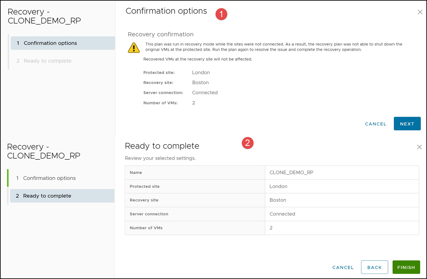
In the unlikely event that the protection site is repaired shortly after the failover to the recovery site, SRM will recognize that not all steps of the previous disaster recovery run were successful. It will request a second running of the recovery plan as shown in Figure 113.
Figure 113. Recovery required after fixing protection site

Select the RUN option to attempt a second recovery. Note in Figure 114 this is not the same as planned migration or disaster recovery. The user is presented no options, other than to allow SRM to attempt to clean up the environment, which is desirable.
Figure 114. Recovery run
A successful run is shown in Figure 115 and Figure 116.
Figure 115. Recovery run completed
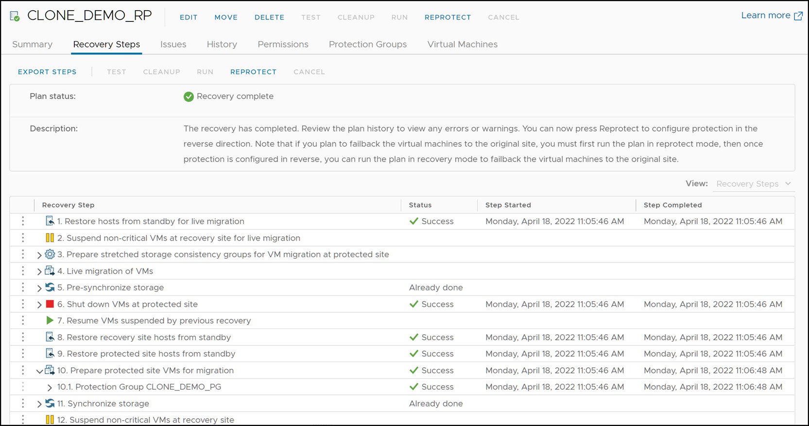
Figure 116. Failover complete

As mentioned, the use of disaster recovery for the recovery plan usually indicates a significant issue that will take time to resolve so this cleanup likely will not be an option.
Recovery after failure of storage and compute environment
In a true disaster scenario, both the compute and storage might become unavailable. This could be due to situations such as:
- Actual physical destruction of the infrastructure
- Loss of power
- WAN failure between the two datacenters, partitioning both network and data replication traffic
In any of those cases, the recovery SRM server will not be able to contact the protected site. This can be seen in Figure 117 which shows the recovery site SRM server reporting that the protection site “London” is down.
Figure 117. Disconnected protected site SRM server

When SRDF replication halts, the RDF pairs enter either a “Partitioned” or “TransmitIdle” state. These RDF pair states are only allowed when the disaster recovery operation is selected not planned migration.
The device group on the recovery site can be queried to verify the “Partitioned” or “TransmitIdle” state of the RDF pairs. Figure 118 shows a device group that is in the “Partitioned” state. Note in the figure that the remote PowerMax SRDF Group cannot be obtained. Also the local (R2) device is still write disabled.
Figure 118. Partitioned SRDF devices

Note: When devices are partitioned, a second query run in Solutions Enabler is advisable. This is because the SRA will only allow an SRDF failover to complete if there are no changed tracks. For the majority of environments, there will be no changed tracks, but if there are a different procedure must be followed which will be covered in the next section.
To recover the virtual machines on the surviving site, select RUN and Disaster recovery. The SRA does not, in principle, act any differently if the “Disaster Recovery” mode is chosen as compared to “Planned Migration”. The SRA will still attempt all operations as it would during a migration and return success or failure. The difference is that SRM will not fail the recovery plan on reception of a failed operation by the SRA. In the case of a protected site complete failure all steps involving the protected site will accordingly fail. Figure 119 shows a recovery plan that has been executed when only the connectivity between the arrays is lost.
Note: If only the array connectivity is impacted, SRM will still offer planned migration as an option, however it will fail and then require running disaster recovery. In such instances it is better to run disaster recovery as errors will be ignored.
Figure 119. Recovery plan execution during a complete protected site failure

During the “Change Recovery Site Storage to Writable” step the SRA will issue an RDF failover command to the SRDF devices. This will cause the R2 devices to become read/write enabled to the recovery hosts. An important difference between an RDF failover during a complete disaster recovery and a planned migration is that the RDF pair state will not change to “Failed Over” after the operation. In this scenario the RDF pair state will remain “Partitioned” until the remote storage is restored at which time it will become “Split”, as both the R1 and R2 are read/write.[3] Figure 120 shows a screenshot of the RDF pairs from earlier in this section after the RDF failover operation. Note the only change is that the local devices are now read/write enabled.
Figure 120. RDF pair state after an RDF failover operation

The remainder of the recovery process is no different in result than the recovery processes discussed earlier in this chapter.
Partitioned state with invalids
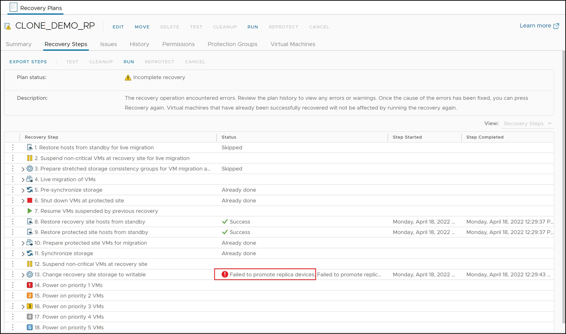
If a Disaster recovery is run and fails with the error “Failed to promote replica devices,” as in Figure 121, review the SRA logs and check for the following error: “The state of invalid tracks on at least one of the RDF pairs makes the current operation not to proceed. Exiting with failure.” This will indicate that the SRA cannot automatically run a failover because of these invalid tracks.
Figure 121. Failed Disaster recovery due to invalid tracks
The invalid tracks can be queried from the recovery site array manager. An example is shown in Figure 122.
Figure 122. Invalids after a partition as seen using Solutions Enabler

The reason the failure occurs is because the failover command would require a -force flag to proceed. While this option may be introduced in a future SRA, currently the failover must be performed manually before proceeding with the Disaster recovery. Remember, however, SRM is intelligent enough to skip steps that are already complete so by failing over manually it will permit SRM to finish the orchestration steps that will mount the datastores and bring up the VMs.
To manually run the failover, first create a text file that lists the RDF pairs - R2 -> R1 as such:
125 11D
151 147
Then from the recovery site array manager issue the failover command with the “-force” flag. An example is show in Figure 123. Note that after the failover, the pairs are still in a Partitioned state because there is no communication with the other array; however see how the local devices are now read/write not write disabled.
Figure 123. Manual failover with invalid tracks

With this step complete, re-run the Disaster Recovery which will now succeed as in Figure 124. Notice that various steps are set to “Already done” due to the previous run as well as the manual failover.
Figure 124. Disaster recovery after manual failover

[1] Disaster recovery mode also tolerates RDF pair states of “Partitioned” and “TransmitIdle” (or TransIdle in CLI) but the use case for these two states is discussed in the next section.
[2] These failed steps can be skipped by selecting the Forced Failover option for disaster recovery.
[3] Note that manual intervention will be required when the protection site is restored as the pair(s) will remain in “Split” state despite the fact a failover has been issued.