
Solution architecture
Solution architecture
-
This section describes PowerFlex software-defined storage replication architecture. Both PowerFlex and SRM support bi-directional setups, meaning a PowerFlex site can simultaneously be a protection and recovery site. The architecture is presented as logical, meaning that the type and version of the PowerFlex system, such as appliance, rack, 3, 4, and so on, is not noted.
Logical architectures
Figure 5 represents an environment where two equal PowerFlex systems are configured, but there is only one active protected site and one idle recovery site. Such an architecture enables the business to continue to run at full capacity at the recovery site in the event of a failure. In other words, the recovery site has all the resources required to run the production workload as it is a mirror image.
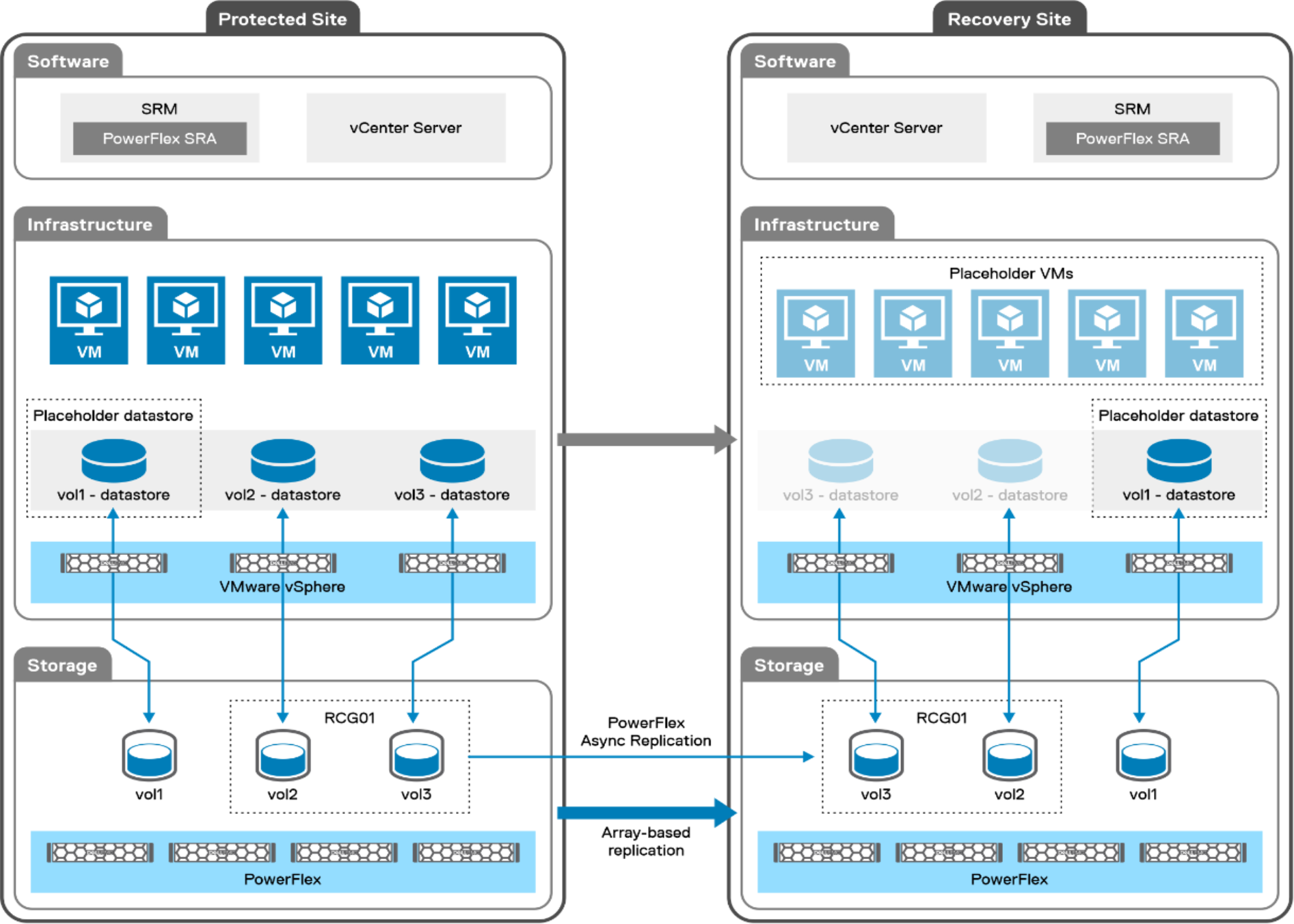
Figure 5. Single directional architecture with PowerFlex replication and SRM
As leaving hardware idle is not an option for many customers, Figure 6, displays the same two PowerFlex systems, but this time each site is servicing VMs and has a role as a protection and recovery site. While this configuration can use all the hardware at both sites, rather than have a system remain idle, it is important to remember that in the event of failure, a single site must run the load from both environments. As such, it is imperative that the business understands the SLAs or service level agreements (if any), and whether they permit a reduction of performance in the event of a failure. It is critical to size the environments appropriately, based on the SLAs, to account for the extra load during a failure.
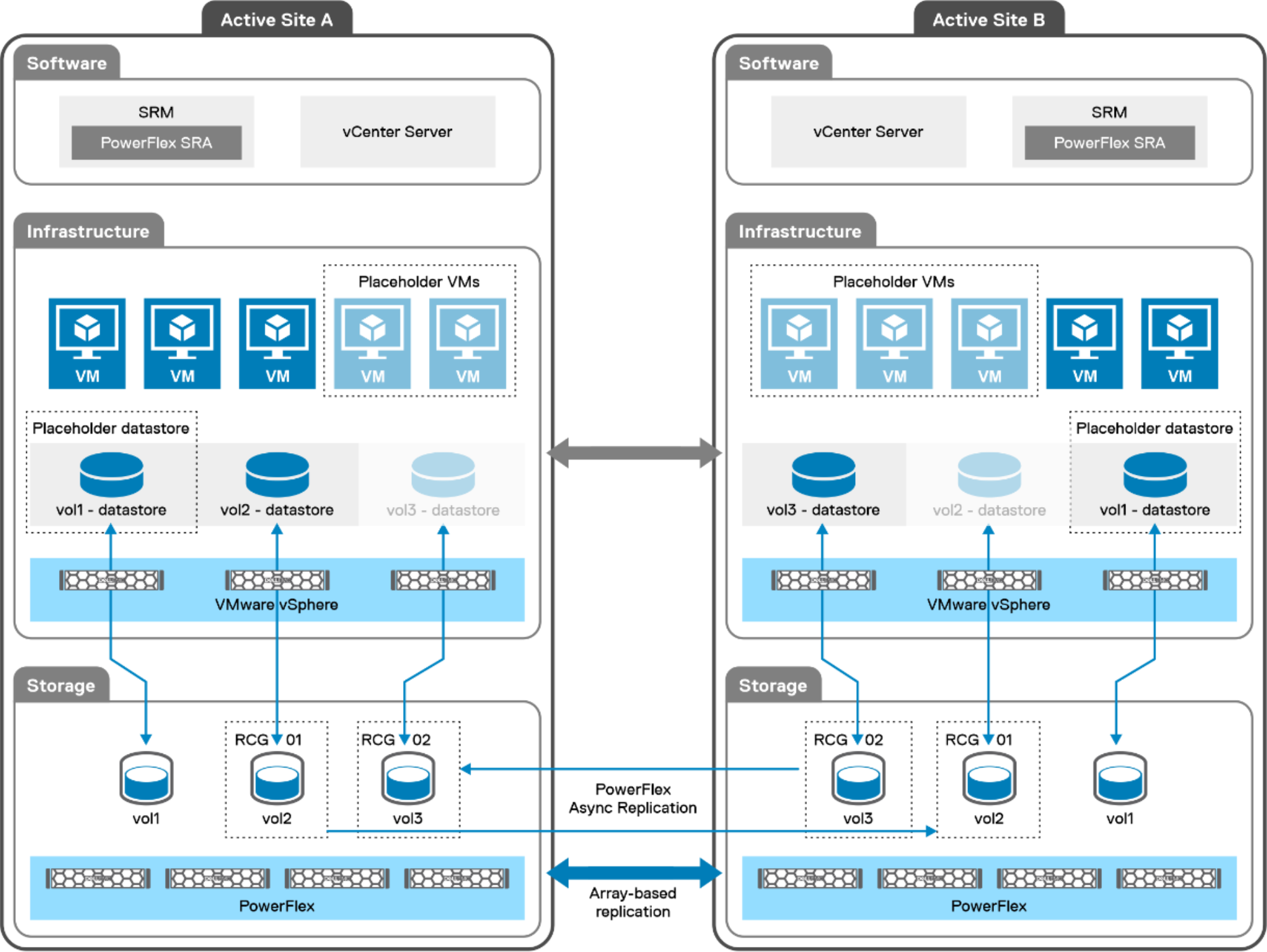 Figure 6. Bi-directional architecture with PowerFlex replication and SRM
Peered systems
The setup of PowerFlex replication is essentially the same for versions 3 and 4. It involves the peering of two systems by sharing root certificates and using the IP addresses of the SDRs. Once paired, each site shows the other as Connected as shown in Figure 7.
 Figure 7. Peered PowerFlex systems