
Replication Consistency Group
Replication Consistency Group
-
The steps to add an RCG in PowerFlex vary between versions 3.5+ and 4.x so each of them are covered separately.
Note: This example, which uses a single source volume, assumes the user mapped it to the ESXi hosts at the protection site and created a datastore on it. Replication is being added after that step is complete. This is not an uncommon practice, though it is also acceptable to present volumes after replication is active.
Steps to add RCG in PowerFlex 3
Log in to the PowerFlex GUI as a user with administrator privilege.
- From the PowerFlex GUI in Figure 8, select Protection > RCGs > ADD.
 Figure 8. Adding RCG - Step 1
- In the next screen as shown in Figure 9, enter the RCG Name, enter the RPO value in seconds or minutes (default is 60 s), select the Source Protection Domain, Target System, Target Protection Domain, and click NEXT.
 Figure 9. Adding RCG - Step 2
- Select the volume from the Source column and then select a volume of the same size from the Target column as shown in Figure 10.
The target volume does not appear in the screen until the source volume is highlighted. Once selected press ADD PAIR and NEXT.
 Figure 10. Adding RCG - Step 3
Note: A volume of equal size must already be present at the target site. PowerFlex 3 auto-provision the volume.
- Review the details shown in Figure 11 to ensure the correct source and target volume pairs are selected and click ADD AND ACTIVATE.
 Figure 11. Adding RCG- Step 4
The volumes begin to synchronize. When the Consistency column moves from Partially Consistent (as shown in Figure 12) to Consistent, synchronization is complete. Since this is asynchronous replication, the remote volume is write-disabled.
 Figure 12. RCG entering consistency
Volume mapping
After creating the RCG, present the remote volume or volumes to the ESXi hosts at the recovery site. The remote volume is mapped as a read-only device. When a test failover or actual failover is required, PowerFlex changes the access of the device to read/write automatically.
The mapping of the replicated remote volume is only possible in the RCG screen, not the Volumes screen. Any attempt to map in the Volumes screen results in the message in Figure 13.
Note: Although Dell Technologies recommends using read-only for access, using a setting of no_access also works.
 Figure 13. Attempted mapping of a volume in an RCG
Go to the RCGs menu on the left-hand side, check the box next to the appropriate RCG in the screen on the right and select Map from the MAPPING drop-down menu as shown in Figure 14.
 Figure 14. Map recovery volumes read-only to recovery site
Next, select the checkbox next to the ESXi hosts in the recovery site, and click MAP. Ensure that the Access Mode is set to Read Only (default). Then click APPLY. This is shown in Figure 15.
 Figure 15. Mapping volumes as read-only to recovery site
The device must appear in the ESXi host under the storage adapter for PowerFlex, as shown in Figure 16, so that is available for mounting when running either test failover or failover. ESXi recognizes the device regardless of the Access Mode.
 Figure 16. RCG read-only volume at recovery site
Steps to add RCG in PowerFlex 4
Log in to the PowerFlex Manager GUI as a user with administrator privilege.
- From the PowerFlex Manager GUI, select the drop-down menu Protection > RCGs. Select +Add RCG in the right-hand corner as shown in Figure 17.
 Figure 17. Add RCG - Step1
- As shown in the following Figure 18, enter the RCG Name, the RPO value in seconds or minutes (default is 60 s), select the Source Protection Domain, Target System, Target Protection Domain, and then click Next.
 Figure 18. Add RCG - Step 2
- In the next step, select the type of provisioning. Unlike PowerFlex 3, PowerFlex 4 offers the traditional ManualProvisioning option and also Auto Provisioning. This is shown in Figure 19.
 Figure 19. Add RCG - Step 3
- If using Auto Provisioning as shown in Figure 20, choose the Type of volume, Thin or Thick, the Storage Pool and select Add Pair and click Next.
 Figure 20. Add RCG - Step 4a
If Manual Provisioning is chosen as shown in Figure 21, select the volume from the Source column and then select a volume of the same size from the Target column and select Add Pair and then click Next. This is similar to PowerFlex 3.
 Figure 21. Add RCG - Step 4b
- In the final step, for Auto Provisioning shown in Figure 22, select Add and Activate.
 Figure 22. Add RCG - Step 5a
Similarly, for Manual Provisioning as shown in Figure 23, select Add and Activate.
 Figure 23. Add RCG - Step 5b
The volumes begin to synchronize. When the Consistency column shows Consistent as shown in Figure 24, synchronization is complete. Since this is an asynchronous replication, the remote volume is write-disabled.
 Figure 24. RCG entering consistency
Volume mapping in 4.0
After creating the RCG, present the remote volume to the ESXi hosts at the recovery site. The remote volume is mapped as a read-only device. When a test failover or actual failover is required, PowerFlex changes the access of the device.
Because of a change in the PowerFlex Manager GUI in PowerFlex 4.0, the mapping of the replicated remote volume is not possible in the RCG screen as there is no mapping menu. The volume must be mapped through the command line interface (CLI). To do this, login to the scli interface as the admin user. Query for the existing replication pairs by running scli –query_all_replication_pairs, and then map the volume read-only to the ESXi host(s) with scli –map_volume_to_host. If there are multiple ESXi hosts, the flag allow_multiple_hosts is required. An example is shown in Figure 25.
 Figure 25. Map volume read-only to the recovery site ESXi hosts
Once the volume is mapped, the PowerFlex environment setup is ready for SRM integration.
Additional pair volume mapping in PowerFlex 4.0
Although it is not possible to map a volume at the target site during the initial RCG creation, the feature is available for additional pairs. Take the following steps to add and map an additional volume pair to an existing RCG.
- Highlight the RCG and select the Modify drop-down menu. Choose Add Pair. Note the menu, as shown in Figure 26, is relocated so as not to obscure the RCG name.
 Figure 26. Adding pairs to an existing RCG
- As previously detailed, begin by selecting the Provisioning Type (not shown), then add the pair. Either provisioning type permits mapping, though in this example Auto Provisioning was selected. After adding the pair, the user is presented with a new Mapping screen. From here, the user can now select which hosts to map the volume to, in a similar manner as PowerFlex 3.
In the screen shown in Figure 27, select the volume, the host, and then choose Map before clicking Next.
 Figure 27. Mapping additional pairs
- Review the summary and select Add Pairs to complete the process as shown in Figure 28.
 Figure 28. Summary of add pairs
The pair is now added to the RCG and mapped to the target host, making it available for use with SRM.
Note: It is possible for the user to create an RCG using scli that contains no pairs, and then add all pairs using the wizard which permits the mapping. This avoids having to map the first volume using scli though CLI is necessary using either method because the GUI does not permit the creation of an empty RCG.
Volume mapping in 4.5
In PowerFlex 4.5, the ability to map the target volumes read-only is re-enabled in the UI. The wizard proceeds like PowerFlex version 3.
- After setting up the RCG, use the checkbox next to the name to highlight it. Then select Mapping > Map as shown in Figure 29:

Figure 29: Mapping target volume read-only in PowerFlex 4.5 – Step 1
2. Highlight the volume(s) and use the double-arrow to move them to the right-hand side of the panel. Then click Next as shown in Figure 30.

Figure 30. Mapping target volume read-only in PowerFlex 4.5 – Step 2
3. Check the box next to the host(s) at the target site and use the double arrows to move it to the right-hand side of the panel. Then click Next as shown in Figure 31.

Figure 31. Mapping target volume read-only in PowerFlex 4.5 – Step 3
4. Use the check box to select the volume(s) and select Read Access from the options at the top. Then click Finish. A warning box appears. The user should select Map RCG Target Volumes. Both the step and warning box are shown in Figure 32.
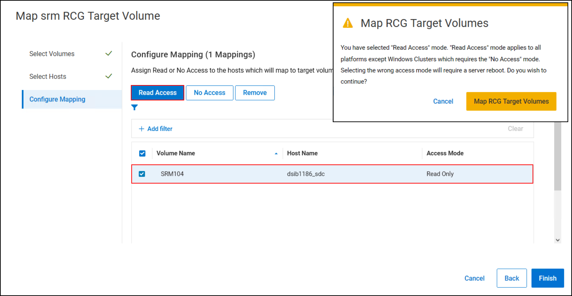
Figure 32. Mapping target volume read-only in PowerFlex 4.5 – Step 4
Once the volume is mapped, the PowerFlex environment setup is ready for SRM integration.