
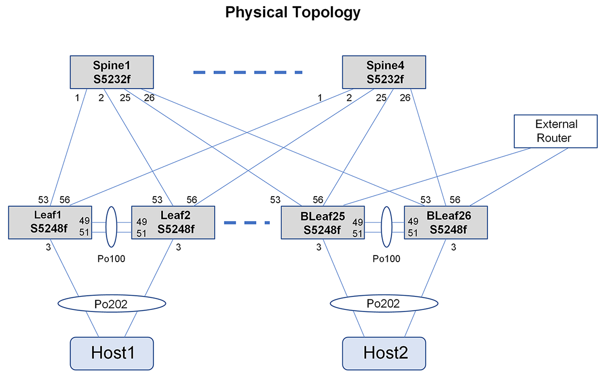
This POC uses a typical leaf and spine topology. The leaf switches are PowerSwitch S5248F-ON switches, and the spine switches are PowerSwitch S5232F-ON switches.
MultiChassis Link Aggregation (MCLAG) is configured on the leaf switches to provide link and device redundancy at the leaf layer.
The following figure shows the physical connections used in the configurations for this POC.
The following figure shows the logical layout of the underlay and overlay networks. Two Virtual Network Instances (VNIs) are deployed between the two leaf pairs depicting the overlay network. The L2 VNI supports stretching the L2 network (Vlan 140) between the leaf pairs. The L3 VNI supports symmetric routing between networks in the same VRF.
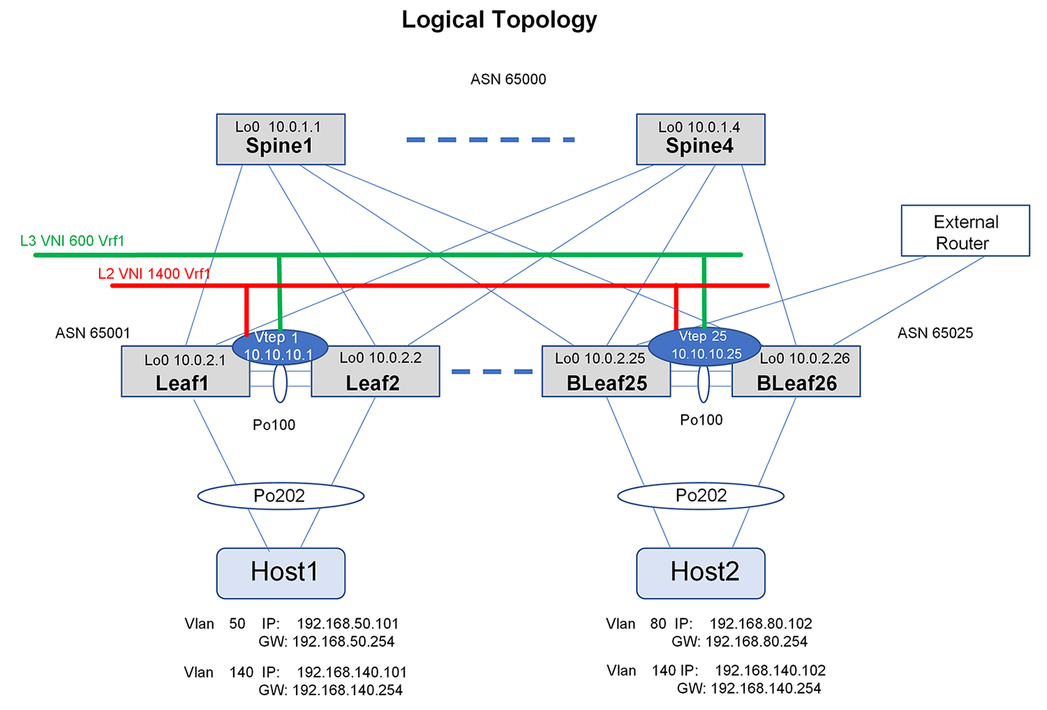
In the preceding figures:
- The leaf and border leaf devices are configured to act as Virtual Tunnel End Points (VTEPs). One Layer 3 VNI is created per Virtual Routing and Forwarding (VRF). IPv4 prefixes learned on the VRF are redistributed into the overlay. The leaf devices are Layer 2 with the hosts.
- Border leaf 25 (BLeaf25) and border leaf 26 (BLeaf26) are peered to the gateway router that is then used to advertise the default route.
- Each host has two paths that connect to two leaf switches through a port channel.
- Each leaf has two paths that connect to the spine.
- Each leaf has a backup path that connects to the peer leaf.