
The following figure shows the twelve storage networks needed to create a dual-link full mesh interconnect between four clustered nodes. The numbered blue lines indicate the recommended cabling order, beginning with the RDMA-capable PCIe adapter in the lowest slot number, Port 1. After cabling storage, connect all nodes, LOM/rNDC/OCP, and Ports 1 and 2 to a management/VM network.
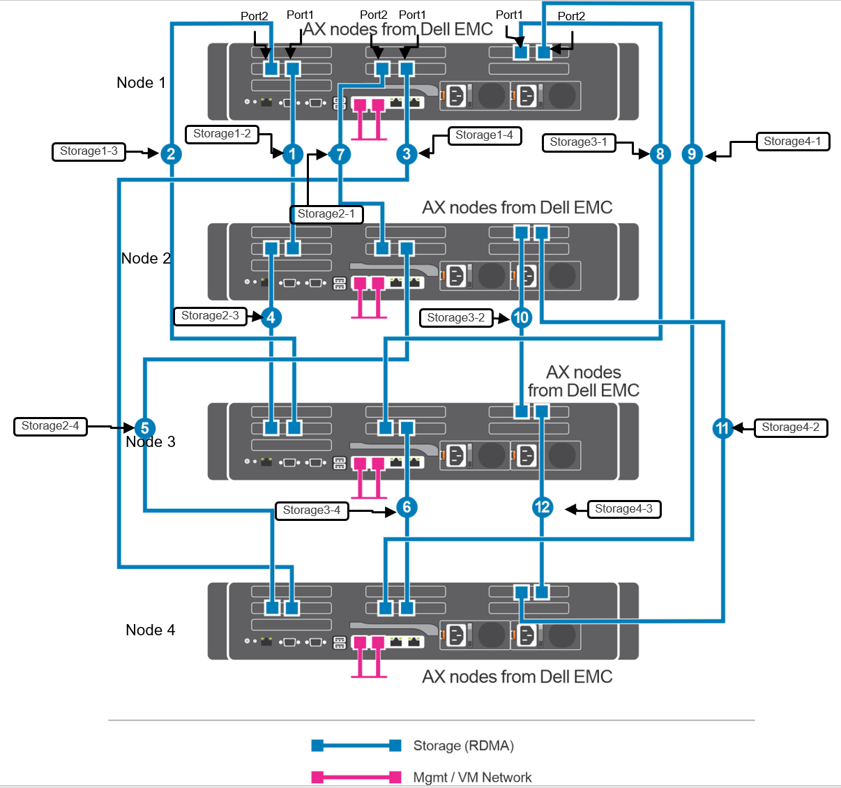
| Node | First port link connection | Second port link connection | Third port link connection | Fourth port link connection | Fifth port link connection | Sixth port link connection |
| Node 1 | Storage1-2 | Storage1-3 | Storage1-4 | Storage2-1 | Storage3-1 | Storage4-1 |
| Node 2 | Storage1-2 | Storage2-3 | Storage2-4 | Storage2-1 | Storage3-2 | Storage4-2 |
| Node 3 | Storage1-3 | Storage2-3 | Storage3-4 | Storage3-1 | Storage3-2 | Storage4-3 |
| Node 4 | Storage1-4 | Storage2-4 | Storage3-4 | Storage4-1 | Storage4-2 | Storage4-3 |