
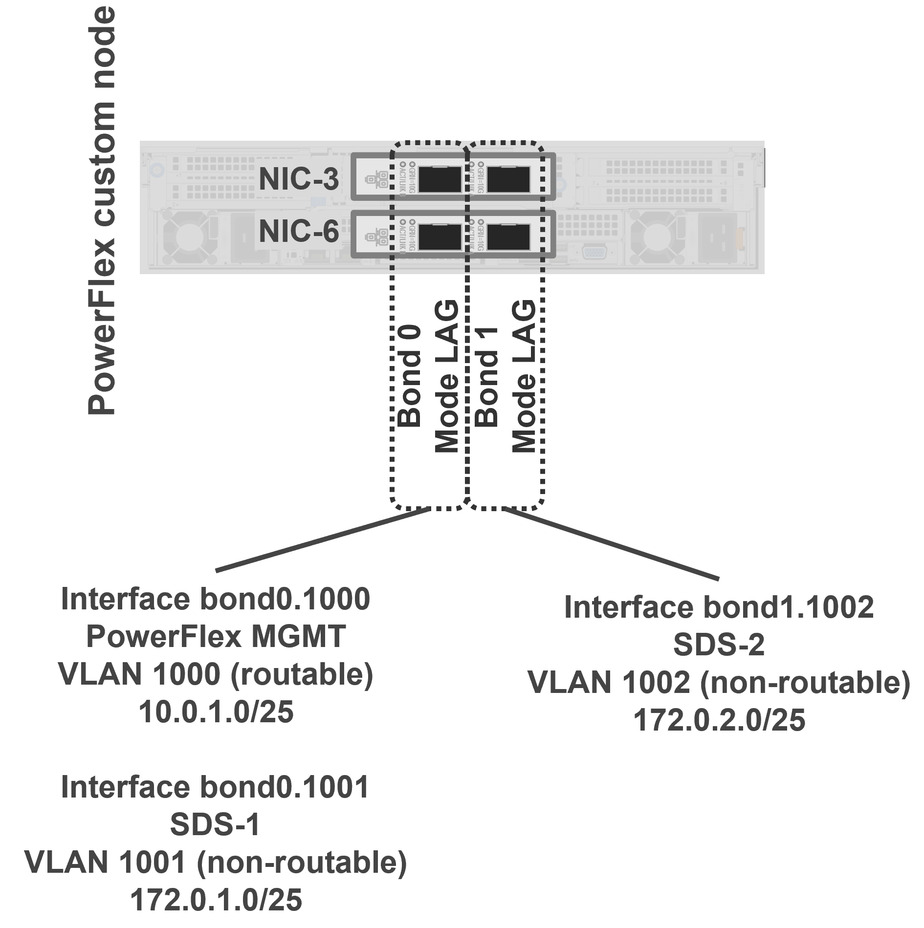
NIC high availability was set up in the SLES operating system on the PowerFlex nodes by creating a bond across the respective ports on each network adapter. A routable VLAN interface was created on Bond 0 for PowerFlex management, and a non-routable interface was also created on Bond 0 for the PowerFlex traffic on the SDS-1 VLAN. Bond 1 was configured to carry storage traffic exclusively over the SDS-2 non-routable VLAN. The following figure shows this configuration:
The following table shows how the NICs for each PowerFlex node were cabled to the corresponding ToR Switches to ensure high availability.
| NIC/Port | Tor Switch |
| Bond 0 - NIC 3 Port 1 | ToR A |
| Bond 0 - NIC 6 Port 1 | ToR B |
| Bond 1 - NIC 3 Port 2 | ToR B |
| Bond 1 - NIC 6 Port 2 | ToR A |