Home > Storage > PowerStore > Data Protection > Dell PowerStore: Clustering and High Availability > Block storage
Block storage
-
The PowerStore architecture implements a fully active/active thinly provisioned mapping subsystem that enables IOs from any path to be committed and fully consistent without the need for redirection. The primary advantage of this implementation is to reduce the time to service I/O requests if some paths were to become unavailable. This approach contrasts with competing architectures that use redirection and single node locking that can result in long-trespass times which increases the chances for data unavailability during failover.
PowerStore implements a dual-node, shared-storage architecture that uses Asymmetric Logical Unit Access (ALUA) for SCSI-based host access and Asymmetric Namespace Access (ANA) for NVMe-oF host access. I/O requests received on any path (active/optimized or active/non-optimized) are committed locally and are fully consistent with its peer node. I/O is normally sent down an active/optimized path. However, in the rare event that all active/optimized paths become unavailable, I/O requests are processed on the local node through the active/non-optimized paths without the need to send any data to the peer node. Then, the I/O is written to the shared NVRAM write cache where the I/O is deduplicated and compressed before being written to the drives. For more information about how the I/O is written to the drives, see the document PowerStore: Data Efficiencies.
ALUA and ANA multipathing ensures high availability. Also, the underlying fully symmetric thin provisioning architecture eliminates the complexity and overhead that is associated with making the volumes available on the surviving path which impacts time to service I/O. To use ALUA and ANA, you must install multipathing software, such as Dell PowerPath, on the host. You should configure multipathing software to use the optimized paths first and only use the non-optimized paths if there are no optimized paths available. If possible, use two separate network interface cards (NICs) or Fibre Channel host bus adapters (HBAs) on the host. This use avoids a single point of failure on the card and the server card slot.
Because the physical ports must always match on both Nodes, the same port numbers are always used for host access in the event of a failover. For example, if 4-port card port 3 on node A is currently used for host access, the same port would be used on node B in the event of a failure. Because of this, connect the same port on both nodes to the multiple switches for host multipathing and redundancy purposes.
Ethernet configuration
PowerStoreOS 2.1 introduced support for NVMe/TCP on PowerStore T model appliances, which allows users to configure Ethernet interfaces for iSCSI or NVMe/TCP host connectivity. The PowerStore 3200Q model also supports NVMe/TCP with the PowerStoreOS 4.0 and later release. You can deploy Ethernet interfaces in mirrored pairs to both PowerStore nodes since these interfaces do not fail over. This configuration ensures that the host has continuous access to block-level storage resources if one node becomes unavailable. For PowerStore T/Q model appliances, storage networks are configured after the cluster is created. For a robust HA environment, create additional interfaces on other ports after the cluster has been created.
To remove a single point of failure at the host and switch level, verify that the PowerStore system has the first two ports of the 4-port card cabled to switches, as shown in the following figure.
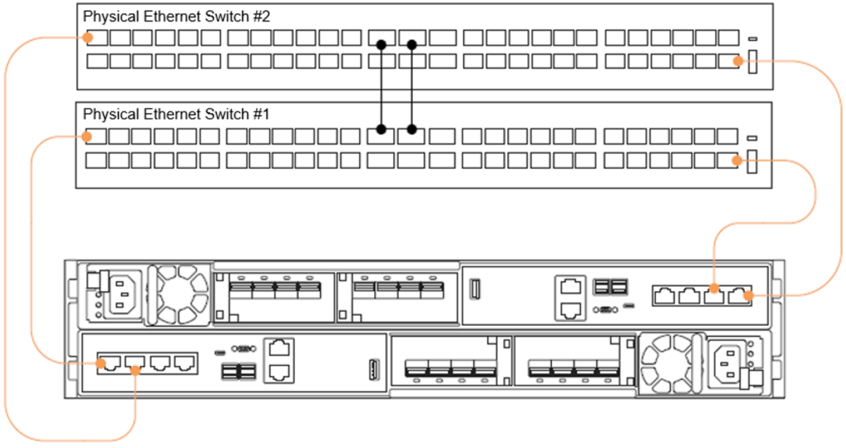
Figure 32. First two ports of the 4-port card cabled to top-of-rack switches
After you configure an appliance, enable other ports for extra bandwidth, throughput, dedicated host connectivity, or dedicated replication traffic. For these ports, cable other ports that are available on the 4-port card or on the I/O modules if available. Because the physical ports match on both nodes, ensure that the ports are cabled to multiple switches for host multipathing and redundancy purposes. For more information about how to enable additional interfaces for replication traffic, see the document PowerStore: Replication Technologies.
After completing cabling, add IP addresses in PowerStore Manager. Figure 33 shows the first step of making sure that there are unused IP addresses configured on the storage network. If there are no other IPs available, click the Add button to supply more IP addresses. The following figure shows the next step on the Ports page for mapping extra ports for host connectivity.
- PowerStore T/Q models: Hardware > Appliance Details > Ports
These ports obtain the next-available unused IP address from the storage network and assign them to the newly configured port. As seen in this example, newly configured ports that are assigned for host traffic are enabled in mirrored pairs. If only one port is selected, there is a notification indicating that the associated port on the peer node is also enabled for host traffic.
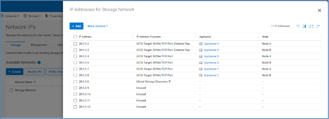
Figure 33. Verify unused storage network IP addresses
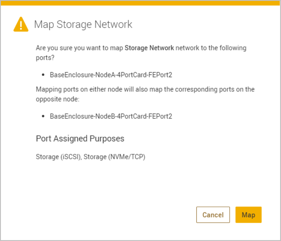
Figure 34. Map Storage Network
Fibre Channel configuration
To achieve high availability with Fibre Channel (FC) and NVMe/FC, configure at least one connection to each node. This practice enables hosts to have continuous access to block-level storage resources if one node becomes unavailable.
With FC and NVMe/FC, you must configure zoning on the switch to allow communication between the host and the PowerStore appliance. If there are multiple appliances in the cluster that are using FC, ensure that each PowerStore appliance has zones that are configured to enable host communication. Create a zone for each host HBA port to each node FC port on each appliance in the cluster. For a robust HA environment, you can zone more FC ports to provide more paths to the PowerStore appliance.
There are two locations where you can locate the port World Wide Names (WWNs) in PowerStore Manager. The first location is in the Hardware > Cluster FE Ports page, as shown in the following figure. The second location is in the Hardware > Appliance > Components > Rear View page, as shown in Figure 36. For more details about configuring hosts, see the document PowerStore Host Configuration Guide on dell.com/powerstoredocs.
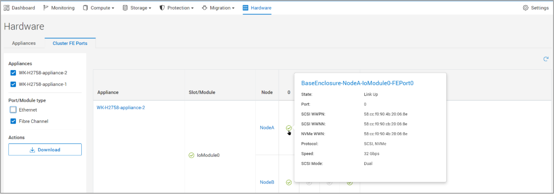
Figure 35. PowerStore Manager hardware cluster front-end ports page
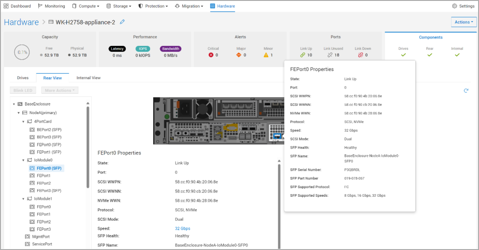
Figure 36. PowerStore Manager components rear view
Block example
When designing a highly available infrastructure, components that connect to the storage system must also be redundant. This design includes removing single points of failure at the host and switch level to avoid data unavailability due to connectivity issues. The following figure shows an example of a highly available configuration for a PowerStore T/Q model system, which has no single point of failure. See the documents PowerStore Network Planning Guide and PowerStore Network Configuration for PowerSwitch Series Guide on the dell.com/powerstoredocs for detailed information about cabling and configuration of the network infrastructure.
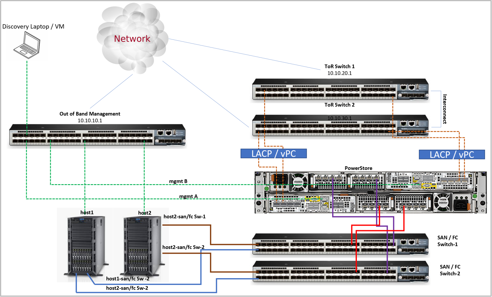
Figure 37. Highly available block configuration
