- Access SmartFabric GUI dashboard, as shown in the figure below.
Figure 245. SmartFabric GUI Summary page 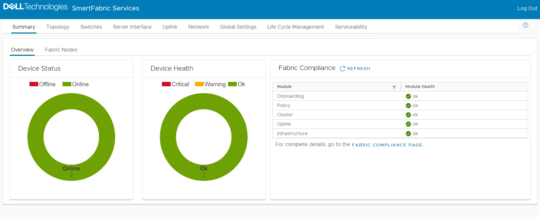
- SFS Nodes Global Setting:
- Change or update rack name, switches are automatically added. Verify the nodes and click Next.
Figure 246. SFS racks page 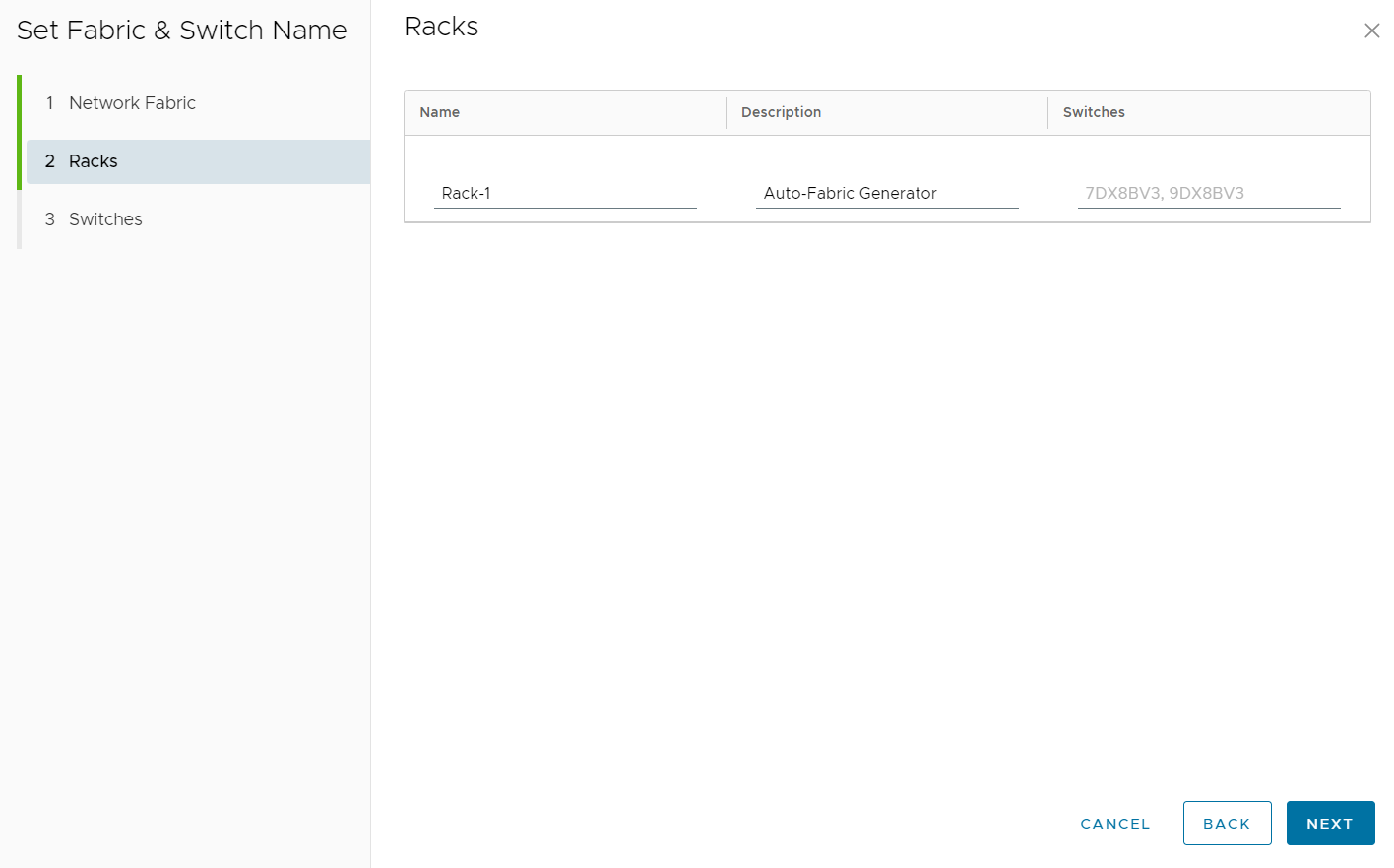
- Switches service tag, role, model, and hostname are populated automatically. The description is optional.
Figure 247. SFS switches page 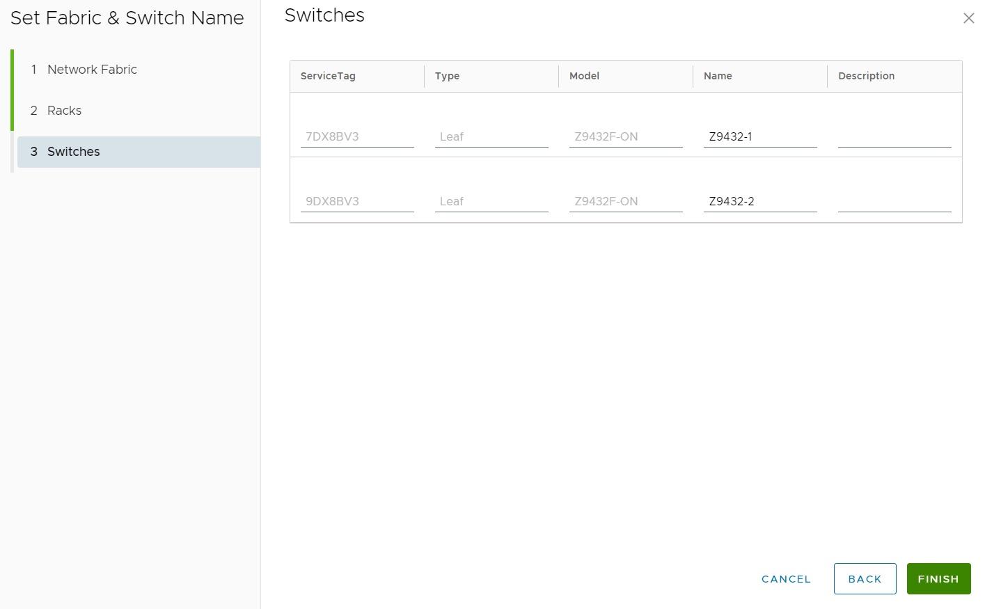
- Change or update rack name, switches are automatically added. Verify the nodes and click Next.
- Ports breakout for upstream switches: By default, Z9432F-ON ports are set to 400GE. If the upstream switch ports run at a slower speed, you must breakout the connected Z9432F-ON ports. This example shows how to change two Z9432F-ON ports from 1x400GE to 1x100GE.
- Select the port and click BREAKOUT PORT.
Figure 248. Breakout ports for upstream switches 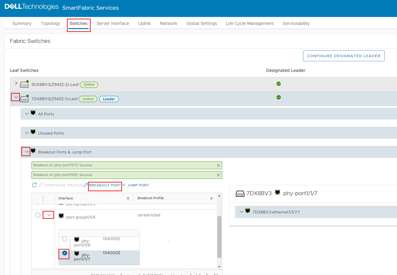
- Select the 1x100GE option from the breakout Mode drop-down menu.
Figure 249. Select port breakout mode 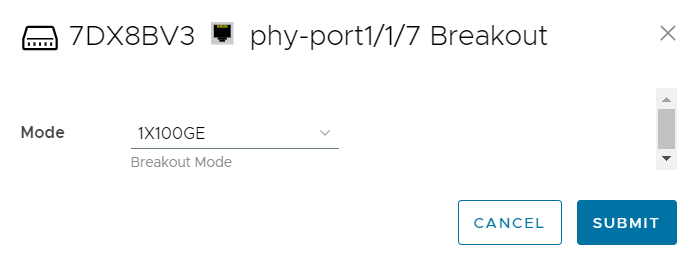
- Select the port and click BREAKOUT PORT.
- VLAN Network configuration:
- Click Create.
Figure 250. Create an internal MGMT VLAN 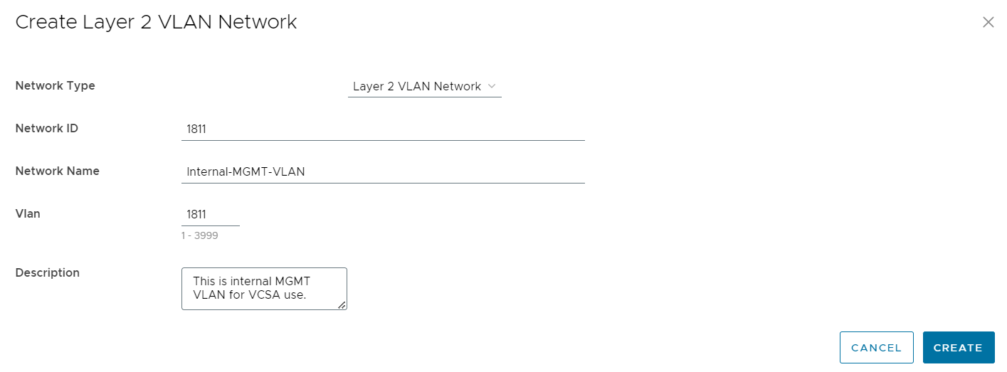
- Note: If more networks are desired for other services in vCenter vDS, create those VLANs as General Purpose Networks and associate them with the Uplink and Server Interface Profile.
- Click Create.
- Create Uplinks to upstream switches:
- Click Next.
Figure 251. Create uplink 
- Click Next.
Figure 252. Uplink port configuration 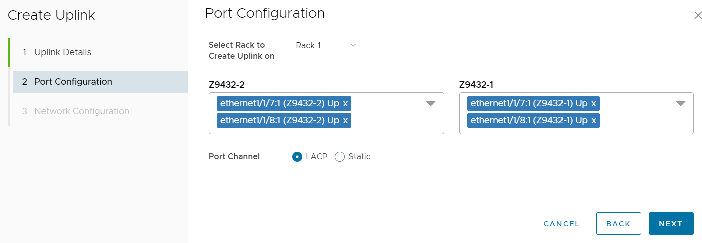
- Click Finish.
Figure 253. Uplink Network Configuration 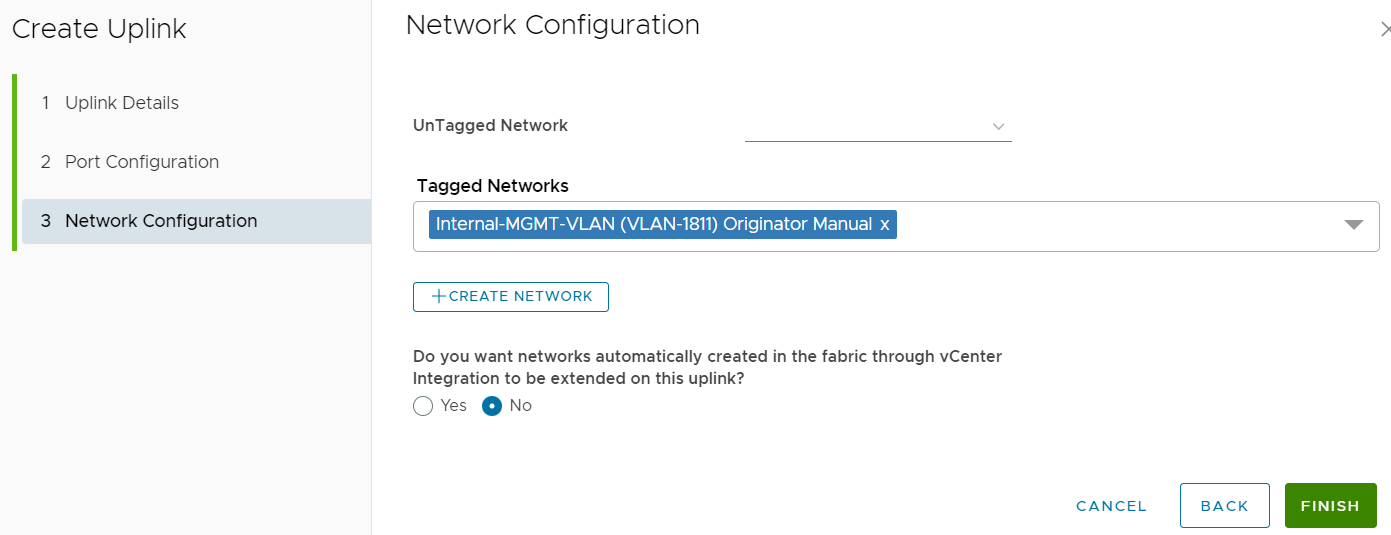
- Click Next.
- Create Server Interface Profile:
- Click CREATE.
Figure 254. Create Server Interface Profile 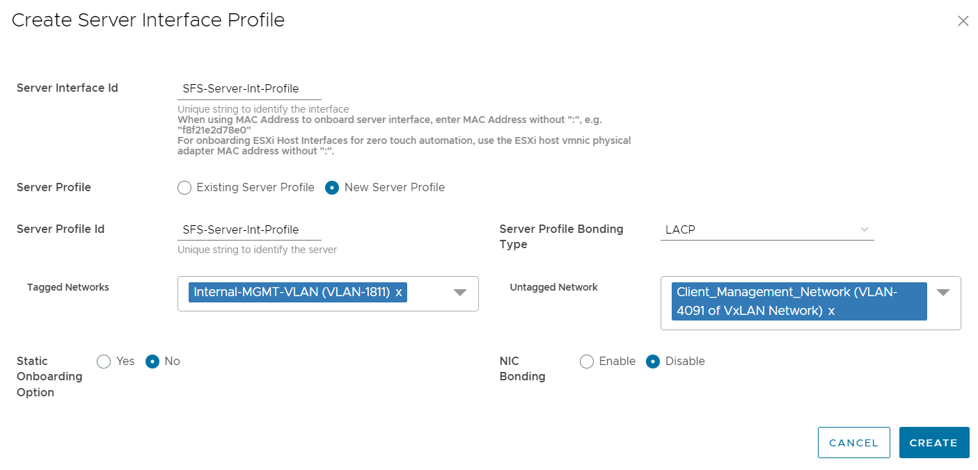
- Click CREATE.
- Port breakout for downstream compute ports:
- Select the port and click BREAKOUT PORT.
Figure 255. Breakout ports for 100 GbE NIC 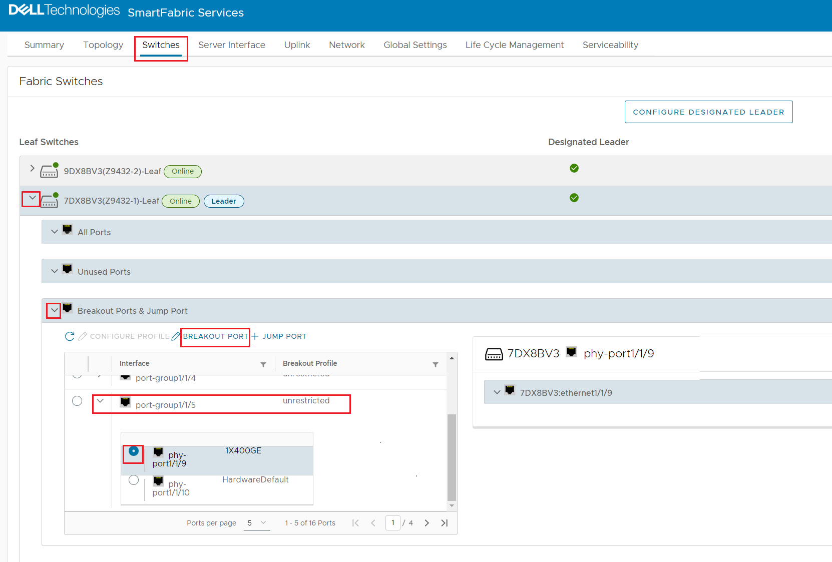
- Select the 4x100GE option from the breakout Mode drop-down menu.
Figure 256. Port breakout mode for 100 GbE NIC port 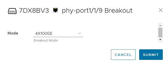
- Port-group1/1/7 is selected for port 1/1/13 to breakout for 25 GbE NIC port.
Figure 257. Port breakout mode for 25 GbE NIC 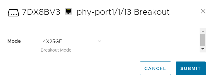
- Select the port and click BREAKOUT PORT.
- Discovering Server Interfaces:
- To discover server interfaces by nodes, click Server Interface > click +IMPORT FROM FABRIC.
Figure 258. Discover Server Interfaces 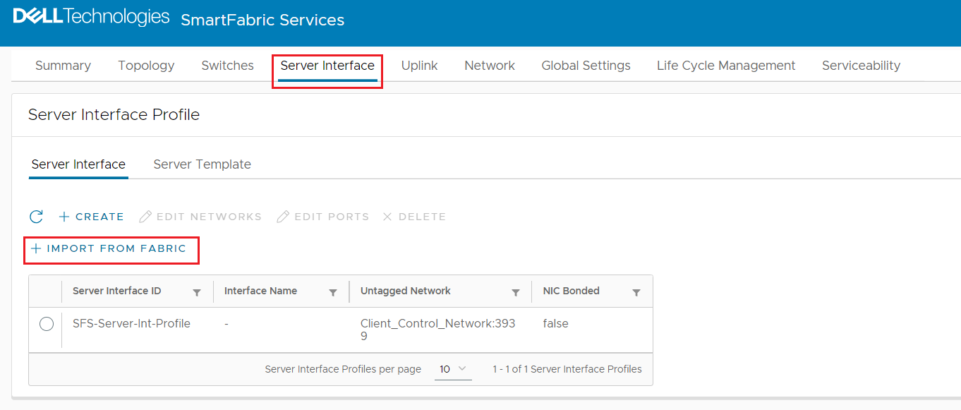
- To add networks to NIC ports, Select discovered NIC ports and click +ADD NETWORKS.
Figure 259. Add networks to NIC ports 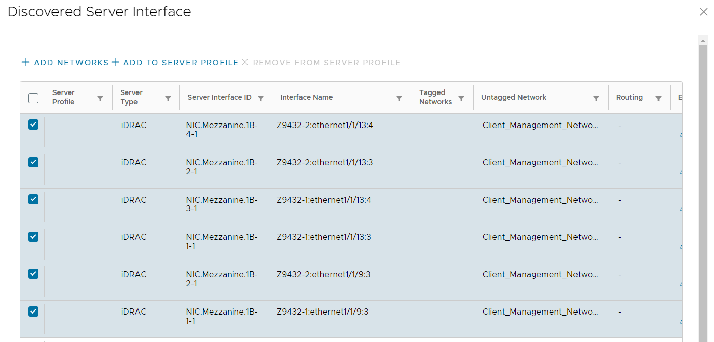
- Click Add.
Figure 260. Add Server Interface Networks 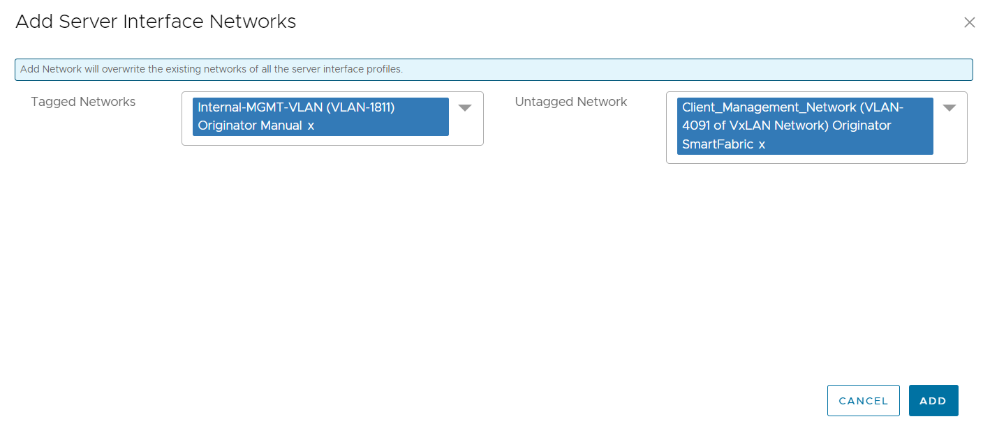
- To add the server profile to the NIC ports, select NIC ports and click +ADD TO SERVER PROFILE.
Figure 261. Add Server profile to NIC ports 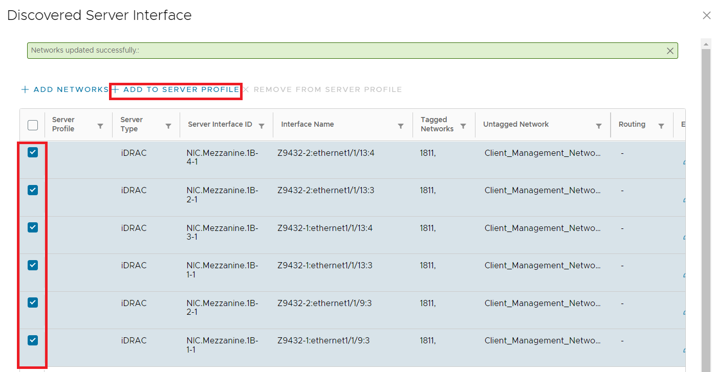
- Click ASSOCIATE to deploy the selected server profile.
Figure 262. Deploy the selected server profile 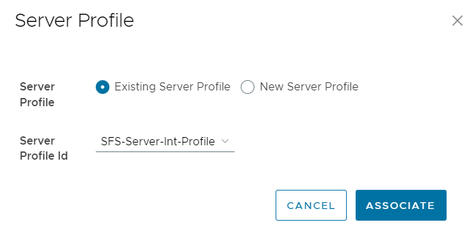
- Select all applicable discovered NIC ports and click CREATE to deploy all network updates.
Figure 263. Deploy all network updates 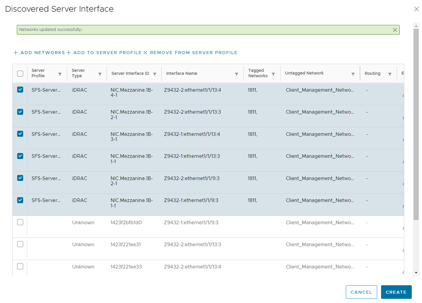
- To discover server interfaces by nodes, click Server Interface > click +IMPORT FROM FABRIC.

Dell PowerEdge MX Networking Deployment Guide
Dell PowerEdge MX Platform Overview
PowerEdge MX Scalable Fabric Architecture
Dell SmartFabric OS10
Full Switch Mode
Overview of SmartFabric Services for PowerEdge MX
SmartFabric Creation
Server Deployment
SmartFabric Deployment Validation
SmartFabric Operations
General Troubleshooting
SmartFabric Troubleshooting
Configuration Scenarios
PowerEdge MX 100 GbE Solution with Z9432F-ON external Fabric Switching Engine
PowerEdge MX 100 GbE and 25 GbE solution with Z9432F-ON FSE in SmartFabric mode
PowerEdge MX 100 GbE solution with Z9664F-ON external Fabric Switching Engine
Advanced NPAR
Additional Tasks
Additional Information
Dell PowerSwitch S4148U-ON Configuration in Scenario 7
Dell PowerStore 1000T
Hardware and Version Information
References