
Networking
Networking
-
This section further explores the production network and best practices for network architects.
Physical connection
We recommend that you use at least two top-of-rack (ToR) switches that work in tandem, using LACP/MLAG or Virtual Link Trunking (VLT). This configuration creates a high availability network for the nodes in the rack. The aggregation of multiple ports results in higher bandwidth, resiliency, and redundancy.
Each node is connected to both switches through two NICs that are aggregated using a Linux bonding driver. The node is configured to bond the two NICs into a single LACP bonding interface. This bonding interface connects one port to each switch, as shown in the following figure:
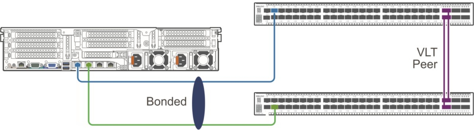
Figure 2. Bonding interface
The switch and node configurations depend on the manufacturer and model. Examples of the configurations from our lab are as follows.
From the switch side:
interface port-channel2
description "xxx-112 ens5f0np0 ens5f1np1 bond"
no shutdown
switchport mode trunk
switchport access vlan xxx
switchport trunk allowed vlan xxx
mtu 9216
lacp fallback enable
lacp fallback preemption disable
spanning-tree port type edge
vlt-port-channel 2
!
interface ethernet1/1/3
description "xxx-112 ens5f0np0"
no shutdown
channel-group 2 mode active
no switchport
mtu 9216
flowcontrol receive on
!
From the node side, under the IPMI console:
> sudo nmtui
Edit a connection
Add
Select "Bond" type
Provide,
Profile name: bond0
Device: bond0
[note: first two interfaces will be used for bond0]
Add Slaves -> Click "Add" -> Ethernet -> Device: <interface-name1> -> Ok. Repeat same for <interface-name2>
Mode: 802.3ad
IPv4 configuration: Type -> Manual
Addresses -> <node-IP>/28
Gateway -> xx.xx.xx.xx
DNS server -> xx.xx.xx.xx
Search domains -> <zone> (xx.xx.xx.xx.xx)
Check -> "Require IPv4 addressing for this connection" and click "Ok" button
Select "activate connection" and check that only bond0 has * enabled and its active and click "back" button
Select "Quit" and OK button
Load balancer
A load balancer is a device that acts as a reverse proxy and distributes network or application traffic across a number of nodes. Load balancers are used to increase capacity (concurrent users) and reliability of applications. They improve the overall performance of applications by decreasing the burden on servers associated with managing and maintaining application and network sessions, as well as by performing application-specific tasks.
MetalLB is leveraged as the software-based network load-balancer implementation in ObjectScale on a bare metal Kubernetes cluster. It integrates with standard network equipment.
MetalLB must be assigned pools of IP addresses from which to allocate services. MetalLB assigns and unassigns individual addresses as services come and go; however, it only hands out addresses that are part of its configured pools. After MetalLB has assigned an external IP address to a service, it needs to make the network beyond the cluster aware that the IP “lives” in the cluster. MetalLB uses standard networking or routing protocols to achieve this, depending on which mode is used: Layer 2 mode or Layer 3 mode (BGP).
In Layer 2 mode, one node assumes the responsibility of advertising a service to the local network. From the network’s perspective, the machine appears to have multiple IP addresses assigned to its network interface. The major advantage of Layer 2 mode is its versatility; it works on any Ethernet network without any special hardware required. In Layer 2 mode, all traffic for a service IP goes to a single node. From there, kube-proxy spreads the traffic to all the service’s pods. In that sense, Layer 2 does not implement a load balancer; rather, it implements a failover mechanism so that a different node can take over should the current leader node fail.
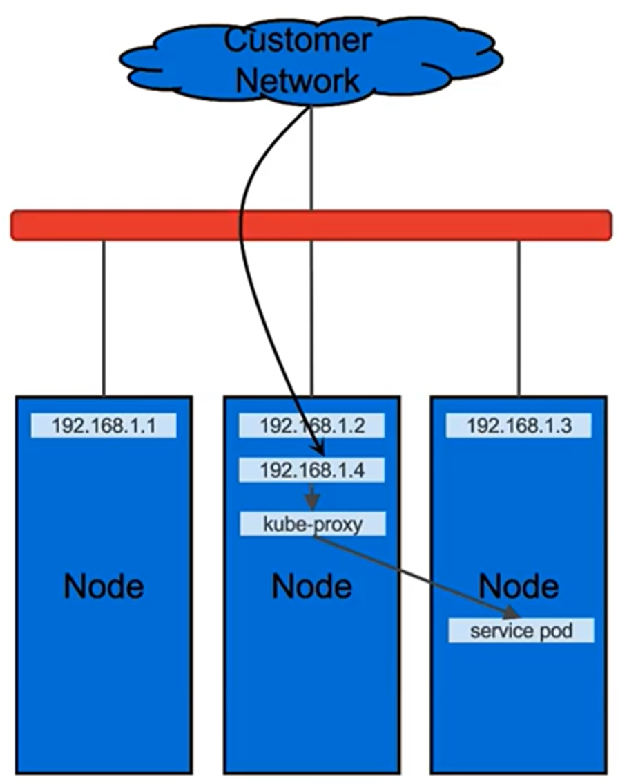
Figure 3. MetalLB Layer 2 mode
Here is an example of the MetalLB configuration in Layer 2 mode with deployment using the OpenShift option:
apiVersion: v1
kind: ConfigMap
metadata:
namespace: metallb-system
name: config
data:
config: |
address-pools:
- name: my-ip-space
protocol: layer2
addresses:
- 192.168.1.1-192.168.1.31
Here is an example of the MetalLB configuration in Layer 2 mode with deployment using the software bundle option:
cluster:
bgpPeers: null
loadBalancerPools:
- name: pool1
protocol: layer2
ipranges:
- 172.16.101.208/28
In Layer 3 (BGP) mode, all machines in the cluster establish BGP peering sessions with nearby routers that you control, and they tell those routers how to forward traffic to the service IPs. Using BGP allows for true load balancing across multiple nodes and fine-grained traffic control, thanks to BGP’s policy mechanisms. After the packets arrive at the node, kube-proxy is responsible for the final hop of traffic routing to get the packets to one specific pod in the service.
The exact behavior of the load balancing depends on your specific router model and configuration, but the common behavior is to balance per connection, based on a packet session are directed to a single machine in your cluster. The traffic spreading happens only between different connections, not for packets within one connection.
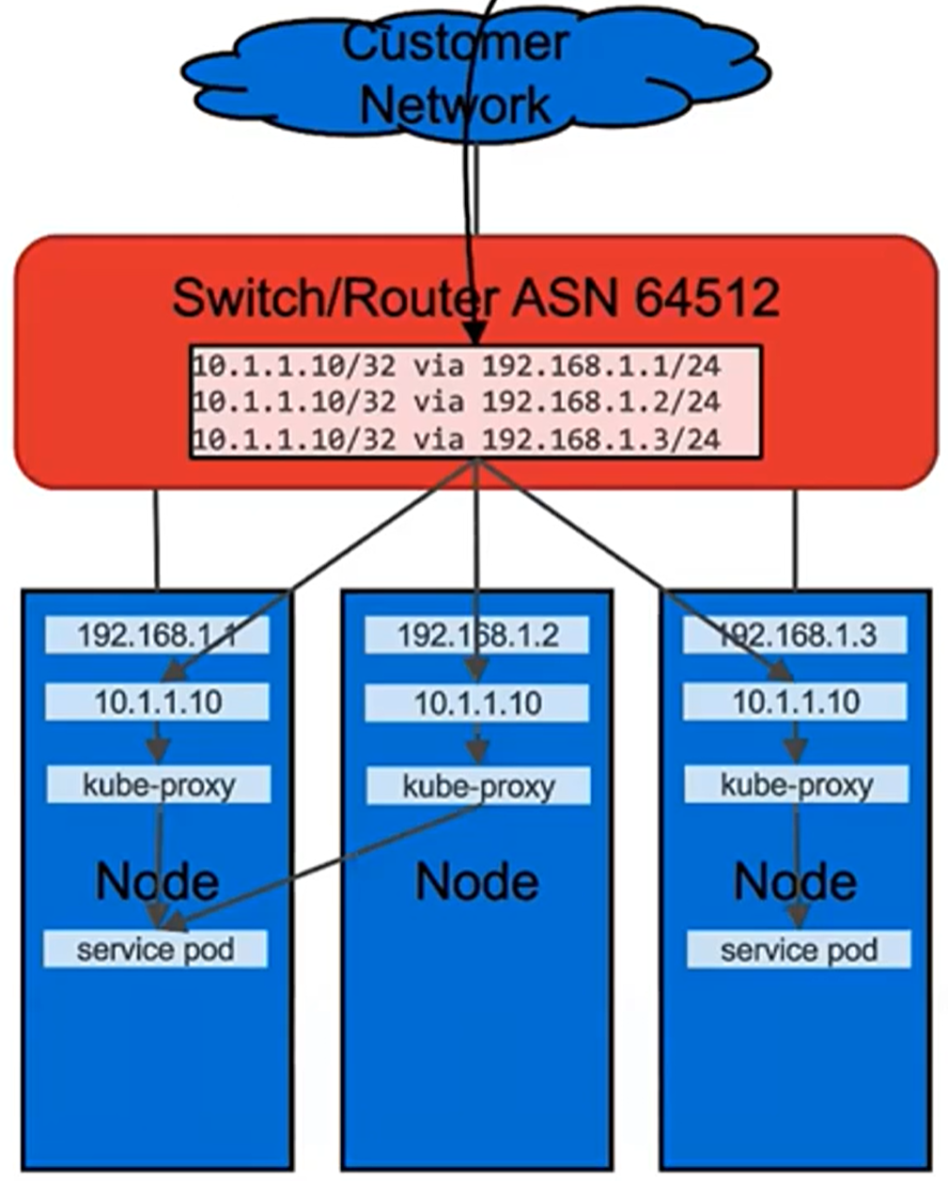
Figure 4. MetalLB Layer 3 (BGP) mode
Here is an example of the MetalLB configuration in Layer 3 mode with deployment using the OpenShift option:
apiVersion: v1
kind: ConfigMap
metadata:
namespace: metallb-system
name: config
data:
config: |
peers:
- peer-address: <gateway1> <----- provide env gateway/switch1 IP
peer-asn: 64512
my-asn: 64520
- peer-address: <gateway2> <----- provide env gateway switch2 IP
peer-asn: 64512
my-asn: 64520
address-pools:
- name: default
protocol: bgp
addresses:
- <floating-ip-range> <--- example: 192.168.1.1/28
avoid-buggy-ips: true
Here is an example of the MetalLB configuration in Layer 3 mode with deployment using the software bundle option:
cluster:
bgpPeers:
- myAsn: 64515
peerAsn: 64512
peeripv4: 172.16.112.253
- myAsn: 64515
peerAsn: 64512
peeripv4: 172.16.112.254
loadBalancerPools:
- name: pool2
protocol: bgp
ipranges:
- 10.246.180.96/27
We recommend using MetalLB Layer 3 (BGP) mode because in Layer2 mode a single leader-elected node receives all traffic for a service IP. This means that your service’s ingress bandwidth is limited to the bandwidth of a single node.
Customers can still use external load balancers with NodePort services. For more information about NodePort, see the Kubernetes documentation.